


Robot track selection often starts with one question: in a plant with several CNC lathes lined up in a row, could a single robot look after every machine in that line? Or a system integrator (SIer) may have sent you a quote for a “robot cell with a track”, and you cannot tell whether the payload, speed and repeatability listed for the track are reasonable. Compared with selecting the robot itself, there is less information about robot tracks, and quotes tend to move forward while the underlying assumptions remain vague.
This article makes one argument. A robot track cannot be selected only by asking whether the stroke and payload are sufficient.
- Payload cannot be compared by a single number. There are cases where the same model shows values for “with an articulated robot” and “static load” that differ by about 2.8 times, and some manufacturers state the load during an emergency stop separately
- Repeatability is “the value for that model in that document”, and the measurement conditions are not stated. Decide first whether any shortfall will be absorbed by compensation on the robot side (vision, etc.)
- For travel time, use the catalog value for the specified travel distance. Do not design with a value you calculated yourself from maximum speed and acceleration (the calculated value comes out shorter)
- Floor foundation and leveling, cables, lubrication, covers, zero point and safety functions are more easily overlooked on the track side than on the robot itself
- A design that shares one robot works when the machine cycle is sufficiently longer than the robot’s round-trip time, and it carries the risk that all equipment stops when the robot stops
That is why it is important for the buyer to have the assumed values written into the RFP (request for proposal) and to measure them in the FAT (factory acceptance test) and SAT (site acceptance test).
Below, for people in charge of production engineering, equipment, maintenance and procurement at Japanese-affiliated machining, automotive parts, metalworking, welding and palletizing plants in Thailand (Chonburi, Rayong, Ayutthaya, Samut Prakan, Pathum Thani, etc.), we cover, in order: track components, sites where tracks fit and where they do not, the 8 selection steps, payload, stroke and travel time, accuracy, drive and mounting, control method, floor, cables and lubrication, safety, how to read manufacturer documents, RFP, FAT/SAT, and costs and benefits. The overall picture of connecting robots to CNC machines is covered in “CNC Machine Tending Automation: A Retrofit Guide“, and external axes that rotate the workpiece are covered in “How to Select a Robot Welding Positioner: A Practical Checklist Beyond Payload“, so this article focuses on “the track that moves the robot itself in a straight line”.
Note that this article does not recommend or rank any manufacturer’s products. Manufacturer figures depend on the definitions and conditions in each document and are not values compared under the same conditions. The model calculation in the second half uses hypothetical figures for this article and is not a quote.
What Is a Robot Track (7th Axis Robot, Robot Transfer Unit)? Components and Names
A device that adds a “7th linear axis” to a 6-axis robot
A robot track is a device that mounts an articulated robot on a carriage and moves it in a straight line along a beam installed on the floor or ceiling. Because it adds a 7th axis to a 6-axis robot, it is called the “7th axis”, and in English it is also called a Robot Transfer Unit (RTU), robot track, track motion, linear unit, and so on.
The names differ by manufacturer. FANUC uses the Japanese term for “travel axis” (RTU in English), the documents of Yaskawa Electric’s European subsidiary use “track” (TSL and TS series), KUKA uses “linear unit” (KL series, operated as the robot’s “external axis”), ABB uses “track motion” (IRBT 2005 / IRT 510), Güdel uses “TrackMotion” (floor-mounted TMF; ceiling, wall and elevated TMO), Rollon uses “Seventh Axis” or “Robot Transfer Unit (RTU)”, and Winkel uses “robot track” (RLE). When reading quotes or overseas documents, keeping in mind that these all refer to the same type of device reduces confusion.
Components

Listing the components that appear in each manufacturer’s documents, in the typical form of a floor-mounted, rack-and-pinion-driven track, gives the following.
| Component | Role | What to check in selection |
|---|---|---|
| Base beam | The structure that supports the carriage over the full length. Güdel describes the floor-mounted TMF beam as “a closed-profile beam that optimally distributes the load to the rails” | Beam division (section length) and joints, difference between overall length and stroke |
| Carriage | The plate or riser that carries the robot and travels. Some products run multiple carriages on the same beam | Number of carriages, robot mounting height (riser), compatibility with the robot model |
| Drive (rack and pinion, belt, etc.) | Converts motor rotation into linear motion | Drive type, reducer, handling of joints, lubrication |
| Guide | Guides the carriage in a straight line. Roller guides, linear guides, etc., depending on the product | Resistance to contamination, ease of maintenance and adjustment |
| Motor and reducer | For robot manufacturers’ own products, the documents describe a configuration driven as an external axis of the robot controller | Control method (external axis or separate control), ease of replacement |
| Cable chain (energy chain) | Supplies power, signals and air to the moving robot | Built-in or external, robot cable length, flexing |
| Floor anchors and leveling feet | Fix the beam to the floor and set it level | Concrete thickness and quality, number and type of anchors |
| Safety fence and end stops | Prevent people from entering and stop overtravel | Combination with safety functions (range and speed monitoring) |
How it differs from “devices that carry the workpiece”
A robot track moves “the robot itself”. Its purpose differs from that of conveying equipment that carries workpieces between stations. Linear transport of workpieces is covered in “Linear Transport System Selection – Comparison, RFP and FAT/SAT for Thai Plants“, and the linear motion components also used inside tracks are covered in “Linear Guide Selection: Life Calculation, Preload, Accuracy and RFP for Thai Factories“.
Where a Robot Linear Track Fits and Where It Does Not
Most reasons for introducing a track come down to “we want one robot to serve several machines or stations”. Whether this idea holds, however, is determined by the machine cycle, the layout, the floor, and the impact when things stop.
| Aspect | Sites where it fits | Sites where it does not fit (consider carefully) |
|---|---|---|
| Machine cycle | The machining cycle is long, and the machine does not wait before the robot completes its round and comes back | The machining cycle is short, and the robot’s round cannot keep up |
| Layout | Stations are in a straight line, or can be rearranged into one | Machines are scattered and cannot be arranged on a straight line |
| Workpiece | Heavy, and difficult to transfer by hand or hand over by conveyor | Light, and can be carried adequately by conveyor or chute |
| Number of stations | Serving multiple stations with one robot reduces the number of robots | One or two machines, where a fixed robot is enough |
| Impact of stoppage | Even if one robot stops, other processes can absorb it | It is not acceptable for all equipment to stop when one robot stops |
| Floor and aisles | The floor is thick, and placing the beam does not block aisles or maintenance routes | The floor is weak, or the beam would block forklift routes or the area in front of machine doors |
Even if your site matches the right-hand column, you do not necessarily have to give up on a track. If you want to keep the floor clear, a configuration with the beam on the ceiling or on an elevated frame (described later) is a candidate. If the machines are scattered, mounting an arm on an AMR (autonomous mobile robot) is also worth comparing. This approach is covered in “Mobile Manipulator Deployment 2026: RFP, Safety and a 90-Day PoC for AMR Robot Arms“.
The most easily overlooked point is “the impact of stoppage”. With four fixed robots, if one fails, the remaining three machines keep running. When one robot is shared on a track, every machine in that line stops as soon as either the robot or the track stops. We will look at this point in numbers in the calculation later.
Robot Track Selection in 8 Steps
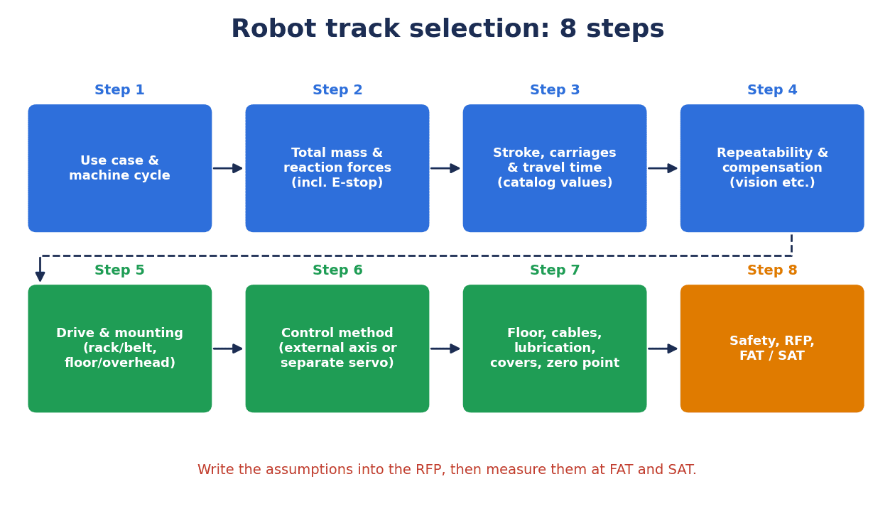
Proceeding through the following 8 steps reduces omissions in track selection. The key is to settle steps 1 and 2 on your own side before looking through catalog tables.
| Step | Content | Main decisions |
|---|---|---|
| 1. Use case & cycle | How many machines and stations to serve, and in what order | Robot work time per machine, machining cycle, round-trip time |
| 2. Total mass & reaction forces | What is mounted on the carriage and how much force acts on it | Mass of robot + gripper + workpiece + riser, maximum reaction forces of the robot (including during emergency stop) |
| 3. Stroke, carriages & travel time | From where to where, with how many carriages, in how many seconds | Stroke, overall length, number of carriages, allowable time per segment |
| 4. Accuracy & compensation | Whether the accuracy needed for workpiece handover comes from the track or from compensation | Required repeatability, whether vision or other compensation is used |
| 5. Drive & mounting | Rack and pinion or belt; floor, ceiling, wall or elevated frame | Drive type, mounting type, environment (chips, dust) |
| 6. Control method | External axis of the robot controller, or a separate servo | Whether synchronized motion is needed, teaching method |
| 7. Floor, cables, lubrication, covers | Installation and maintenance conditions | Floor thickness and quality, cable routing, lubrication method, covers |
| 8. Safety, RFP, FAT/SAT | Safety functions and acceptance criteria | Range monitoring and speed monitoring, stopping distance, acceptance test items |
The following sections follow the order of these steps.
Payload: Do Not Compare Robot Tracks by a Single Number
A case where the same model differs by “about 2.8 times”
The first thing you see in a track catalog is probably “payload”. However, the definition of this number differs between manufacturers.
Güdel’s Robotics catalog (May 2026 edition) lists the maximum payload of the floor-mounted TMF-2 in two columns: “Articulated robot 9,000 N / Static load 25,000 N”. Converted to kg for this article using a gravitational acceleration of 9.80665 m/s², 9,000 N is about 918 kg and 25,000 N is about 2,549 kg, a gap of about 2.8 times for the same model. The wall/overhead TMO-2-W is also listed in two columns, “Articulated robot 6,300 N / Static load 11,000 N” (about 642 kg / about 1,122 kg, converted for this article). The catalog has no definition for the “Articulated robot” column, so which load conditions the value assumes needs to be confirmed with Güdel.
Güdel’s TMF-5 fact sheet (August 2026 edition) separately states a “static load capacity of 11,680 kg” and a “robot weight (including payload) of 6,300 kg”. Here too, the judgment changes depending on which number you look at.
Dynamic loads and emergency stop loads
In its article on 7th axis selection, Rollon explains that “the starting point for sizing is load: there is the static load determined at rest by robot mass, payload and center of gravity, and the dynamic load that acts during acceleration and deceleration”, and writes that “an axis that makes short moves occasionally at medium speed and one that constantly cycles at maximum acceleration experience completely different stresses, so it makes sense to start selection from the duty cycle and cycle time” (the vendor’s view).
Some manufacturers also state the load during an emergency stop separately. Winkel lists a “maximum emergency stop torque” for each RLE series model (15 kNm for the RLE-300, 250 kNm for the RLE-10000), and in the allowable load diagrams for the TMF-2 and TMO-2-W, Güdel draws an “emergency stop” line separate from the line of recommended basic values for a service life of 10⁷ m. The documents of Yaskawa Electric’s European subsidiary state “ED (duty) 50%” for each TSL model.
Check in the documents whether the value “includes the robot”
Yaskawa’s “Maximum payload” (European documents), ABB’s “Payload” and KUKA’s “Payload” each have numbers in their documents, but the documents reviewed for this article do not define whether these are totals including the robot body mounted on the carriage, or under what conditions they apply. In this article, therefore, whenever we list figures we always add “as defined by each manufacturer”.
In the RFP, the reliable approach is to pass the following information, using the robot manufacturer’s values, to the track manufacturer and have them confirm that the track side can handle it.
- Mass and center of gravity of the robot body, gripper, workpiece and riser
- Maximum reaction forces and reaction moments of the robot (including during emergency stop)
- How it will be moved (acceleration, frequency of travel back and forth, duty)
For the robot types themselves and how to choose payload, see “Industrial Robot Implementation 2026 — 5 Types, Prices and How to Choose“.
Stroke, Carriages and Travel Time
Overall length and stroke are different
The “length” of a track includes the overall length of the beam and the distance the carriage can actually move (stroke, travel length). The difference between the two varies by product.
- Yaskawa (European documents): for TSL-600 / TSL-1000, stroke = standard length L − 850 mm; for TSL-1400 / 2000 / 4000, stroke = L − 1,340 mm
- ABB IRBT 2005 (2015 product presentation): the shortest standard length of 2.23 m gives a travel length of 0.8 m, and the longest standard length of 21.23 m gives a travel length of 19.8 m. The minimum length and maximum travel length change with the number of carriages
- KUKA KL 4000: overall length 31.5 m, travel 30.4 m
When four machine tools are lined up, whether the robot can reach the front of the machines at both ends depends not only on the stroke but also on the robot arm’s reach and the robot’s orientation on the carriage. The overall length of the beam is longer still, so enter the overall length on the plant layout drawing and check for interference with aisles and columns.
How strokes are extended
How long strokes are built also differs by manufacturer.
- FANUC modular RTU: a combination of 3 types of track modules (stroke 1 m, 1.5 m, 2 m) and 3 types of extension modules (1.5 m, 2.5 m, 3.5 m), from 1 m up to a maximum of 20 m in 0.5 m increments (development announcement, May 2024)
- ABB IRBT 2005: connects 1 m long modules (each a single casting)
- Yaskawa TSL-2000/4000 (European documents): a 4 m initial module extended in 2 m increments up to 24 m
- Güdel TMF-5: stroke 1 to 98 m in 1 m increments (August 2026 fact sheet)
- Winkel RLE: maximum length of one section 11,500 mm, maximum stroke 60,000 mm
- Rollon RTU: “theoretically unlimited stroke” with joinable self-centering inserts (vendor claim)
The longer the track, the more beam joints there are. In its proposal for a track unit for the FANUC CRX (as of October 2025), OMRON lists as an issue that “the rack and pinion and linear guides used in conventional travel mechanisms require joints when made long, and assembly skill is needed”. Assembling and checking joints directly affects the quality of the installation work.
Number of carriages
Some products run multiple carriages on a single beam. KUKA states “up to 4 carriages operated simultaneously” for the KL 4000, Güdel states “number of carriages: up to 4” for the TMF-5, and Yaskawa (European documents) lists a “second carriage” as an option. KUKA also writes on its overview page that “up to 4 robots can be operated on one linear unit”. When adding carriages, also check interference between carriages and the cable routing.
For travel time, use “the catalog value for the specified distance”
Travel time is the easiest thing to get wrong in cycle calculations. When a catalog lists maximum speed and acceleration, it is tempting to calculate travel time from a trapezoidal velocity profile. However, that calculated value can come out shorter than the actual value.
According to Yaskawa’s European documents, the TSL-1000 has a maximum speed of 1.8 m/s, acceleration of 1.6 m/s², and travel times of “500 mm 1.0 s / 1,000 mm 1.38 s”. Calculating the time for a 1,000 mm move using only maximum speed and acceleration, the midpoint is reached before acceleration alone reaches maximum speed, so the velocity profile becomes triangular: 2 × √(0.5 ÷ 1.6) ≈ about 1.12 s. This is about 0.26 s shorter than the 1.38 s in the document. The breakdown of the difference (settling time, etc.) is not given in the document, so in design it is safer to use the catalog travel time as is.
| Yaskawa model (European documents) | Maximum speed | Acceleration | Travel time (document value) |
|---|---|---|---|
| TSL-600 SY | 2.14 m/s | 2.38 m/s² | 500 mm 0.85 s / 1,000 mm 1.16 s |
| TSL-1000 SY | 1.8 m/s | 1.6 m/s² | 500 mm 1.0 s / 1,000 mm 1.38 s |
| TSL-1400 SY | 2.5 m/s | 2.5 m/s² | 500 mm 0.63 s / 1,000 mm 0.93 s |
| TSL-2000 SY | 1.7 m/s | 2.14 m/s² | 1.45 s (the stated travel distance differs between documents) |
| TSL-4000 SY | 1.3 m/s | 1.5 m/s² | 1.93 s (same as above) |
For the TSL-2000 / 4000 values of 1.45 s / 1.93 s, the March 2025 single-product document and the October 2025 series document state differently how many mm of travel the value refers to. When using such values, the reliable approach is to confirm in writing with the manufacturer “the distance of this segment and the conditions of the mounted robot and load”.
Güdel lists acceleration time and acceleration distance in its catalog. The articulated robot column for the TMF-2 shows speed 150 m/min (2.5 m/s), acceleration 4 m/s², acceleration time 0.63 s and acceleration distance 0.78 m. These are calculated values, matching speed ÷ acceleration (2.5 ÷ 4 ≈ 0.625 s) and speed squared ÷ (2 × acceleration) (2.5² ÷ 8 ≈ 0.78 m). However, these are values for the acceleration phase, and the time for deceleration and settling after stopping is not shown. When requiring travel time in the RFP, specify “which segment, with which load, how many seconds including settling”.
Repeatability and Compensation
Each manufacturer’s value is “the value for that model in that document”
Manufacturers state track repeatability as follows (as defined by each manufacturer; no document states the measurement conditions).
| Manufacturer and model (document) | Repeatability as stated |
|---|---|
| KUKA KL 4000 / KL 250-3 (product page) | ±0.02 mm (Repeatability) |
| Güdel TMF-2, TMO-2-W (catalog, May 2026 edition), TMF-5 (fact sheet, August 2026 edition) | r = ±0.02 mm (Precision (Repeatability)) |
| ABB IRBT 2005 (product presentation, November 2015) | ≤ ±0.05 mm (Repeatability). The current IRT 510 page lists “Pose repeatability ≤ ± 0.05” without a unit |
| Yaskawa TSL series (European documents) | ±0.05 to ±0.08 mm (Repetitive position accuracy. TSL-600 ±0.05, TSL-1000 ±0.06, TSL-1400, 2000 and 4000 ±0.08) |
| Winkel RLE (data sheet on product page) | RLE-300 to 3000 ±0.1 mm, RLE-10000 ±0.2 mm |
The terms also differ: “Repeatability”, “Pose repeatability”, “Repetitive position accuracy” and “Precision (Repeatability)”. As long as conditions such as temperature, load and measurement position are not in the documents, you cannot decide which manufacturer is better from the size of the numbers in this table.
Achieve accuracy with the track, or with compensation
What matters in selection is to first decide on the process side “how many mm of accuracy the workpiece handover requires”, and then choose whether to meet it with the track’s repeatability or absorb it with compensation on the robot side.
One example is OMRON’s proposal (published by distributor Daido) for a track unit for the FANUC CRX. The proposal states that “even without high-precision positioning capability in the travel mechanism, positioning compensation is possible with the CRX option camera and marker compensation function (patent pending)” and that “during robot operation, the slide plate is held by a brake to improve positioning accuracy” (vendor claims). This proposal does not give a repeatability figure for the track. The idea is not to demand high accuracy from the track itself, but to have the robot look at a reference marker at the stopped position and compensate.
When using compensation, also confirm in the RFP whether the time required for compensation is added to the cycle, and how marker contamination and changes in lighting will be handled.
Drive Type and Mounting: Rack and Pinion Robot Track, Belt and More
Rack and pinion and belt
In the documents reviewed for this article, robot tracks are driven mainly by rack and pinion or belt, and there was also an example of wire drive.
| Drive type | What manufacturers state (vendor claims) | Points to check |
|---|---|---|
| Rack and pinion | Güdel TMF-5: “hardened helical-tooth rack and pinion, Güdel HPG120 reducer”. Winkel RLE: “hardened rack and pinion, backlash-reduced reducer”. Yaskawa TSL: “rack drive”. The rack-and-pinion version of Rollon’s aluminum-body RTU is for “robots up to 1,500 kg”, and the steel-bodied Steel RTU is for “robots from 20 kg up to the maximum payload” | Handling of joints, rack lubrication, backlash adjustment |
| Belt | The open-belt and shielded-belt versions of Rollon’s aluminum-body RTU are for “payloads up to 20 kg”. Rollon explains that “in environments with a lot of metal chips and welding spatter, a sealed (shielded) belt reduces contamination of internal components; in clean environments an open belt can be more cost-effective” | Upper payload limit, environment (chips, spatter), tension inspection |
| Wire | OMRON’s track unit for the CRX: “the drive section is a wire unit”, “linear roller guide that is easy to extend” | Supported robots (CRX5/10/20; CRX30 on inquiry), stroke |
For robot tracks driven by ball screws or linear motors, our research for this article found no product whose specifications we could confirm. If such a method is proposed, have the same assumed values provided along the RFP items (described later) before comparing.
Floor, ceiling, wall and elevated frame
In its Robotics catalog (May 2026 edition), Güdel divides mounting types as follows (vendor claims).
| Mounting type (Güdel model) | Güdel’s description | Example reasons to consider it |
|---|---|---|
| Floor (TMF) | Roller guides make it resistant to contamination and highly rigid. Made in segments, the axis length can be extended up to 100 m | Heavy robots, long strokes |
| Ceiling (TMO-C) | Placed centrally directly above the robot’s work area, securing the maximum work area in the horizontal plane. Suited to processes accessed from above | Keeping the floor clear, handling workpieces from above |
| Wall (TMO-W) | Suited to cases where building height is constrained. The main work area is below and to the side of the axis | Insufficient ceiling height |
| Elevated frame (TMO-E) | Complements the floor-mounted TMF. Because it is raised off the floor, existing production areas can be used effectively, with good access to processes and machines | Keeping the floor in front of machines and forklift routes clear |
Other products are also stated to support overhead mounting. KUKA gives the mounting position of the KL 4000 as “Floor, ceiling” and describes the KL 100 as “for KR AGILUS mounted on floor, ceiling or wall” (the KL 250-3 is “ground” only). Winkel states “upright position: yes / hanging position: yes” for the RLE-1500 and says it can be “used as a floor track or as a portal (gantry)”. Yaskawa’s TS-100D (European documents) offers “optional ceiling mounting on a gantry” (columns 1,600 to 2,400 mm), and Rollon describes “floor, wall and ceiling mounted configurations”.
Whether to choose floor or overhead mounting depends on the robot’s payload, the building structure, how the machine doors open, and access during maintenance (the working space needed to replace the robot or motors). For overhead and elevated mounting, check whether the design of the structure supporting the beam, and the foundation of that structure, are included in the scope of the quote.
Control Method: Robot External Axis Control or a Separate Servo
Control as an external axis of the robot controller
The robot manufacturers’ own tracks reviewed for this article are described as configurations controlled together with the robot controller.
- Yaskawa (European documents): “TSL tracks are fully synchronized with the robot control system, and operation and programming are done with the robot’s teach pendant”
- KUKA: “Linear units are controlled by the same controller as the robot and can be integrated into work sequences without additional equipment”. The KL 250-3 page says it is “integrated into the robot controller as a mathematically coupled axis, and no additional controller is needed”
- FANUC: the modular RTU provides “software functions such as life prediction according to robot posture and collision detection”. The May 2024 development announcement states that the controller can be chosen from the R-30iB Plus and the new R-50iA
- ABB: the IRBT 2005 “integrates seamlessly with the robot system through TrueMove and QuickMove” (2015 product presentation)
All of these are vendor claims. When controlled as an external axis, the robot and track can be taught with a single teach pendant, and motions in which the robot works while traveling (such as following a weld seam) can be created.
Driving it with a separate servo
The other approach is a configuration in which the track is driven by a separate servo system. The OMRON track unit for the CRX mentioned earlier “mounts OMRON’s AC servo system 1S series, safety-function-compatible type, on the track” and “comes with a sample program that moves to a pre-taught position when started by specifying a number (the CRX motion program is not included)”. This is neither a FANUC genuine product nor an external axis of the robot controller; the robot works on top of the stopped track, and travel is coordinated as moves to specified positions.
Rules of thumb
| Aspect | Synchronized as an external axis | Separate servo / separate control |
|---|---|---|
| Suited motions | Robot works while traveling (following a weld seam, etc.) | Only moving between stations |
| Teaching | Taught together with the robot’s pendant | Travel positions taught separately, coordinated with the robot by signals |
| Software integration | Collision detection, life prediction, etc. on the robot side (FANUC example) | Depends on the functions of the track-side servo |
| Safety | Some products allow the robot-side safety functions to monitor the external axis | There is a proposal aiming for fenceless operation with a servo that has safety functions (OMRON) |
In either configuration, a risk assessment before introduction is essential. OMRON’s proposal also clearly states that “the customer needs to carry out a risk assessment before introduction”. “Servo Control Procurement and FAT/SAT Guide for Thailand Plants in 2026” is also a useful reference for how to approach ordering and acceptance of servos.
Floor Foundation and Leveling
Select on the assumption that there is no perfect floor
Rollon writes that “long tracks are rarely placed on a perfectly machined foundation. Floors are uneven, columns impose constraints, and the track often has to fit existing equipment, so the mounting concept and alignment functions are as important as load capacity” (the vendor’s view).
The leveling mechanisms also differ by product.
- ABB IRBT 2005 (2015 product presentation): integrated leveling feet make level adjustment easy, serve as a guide when drilling, and allow M16 anchors to be set without moving the whole track. A special tool is required for adjustment
- Güdel TMF-5: floor leveling kit with anchor rods
- KUKA KL 4000: the frames are bolted, with no welding required, and can be readjusted at any time
- Winkel RLE: easy floor adjustment
Güdel’s floor anchor table is “the condition for Güdel products”
An example that states floor requirements in concrete numbers is the anchor table in Güdel’s Robotics catalog (May 2026 edition). For the basic anchors (option 151), it sets the concrete quality at a minimum of 20/25 (EN 206-1) and gives the anchor and the minimum concrete thickness (hmin) for each model.
| Applicable Güdel models (excerpt) | Anchor | Concrete thickness hmin | Edge distance cmin |
|---|---|---|---|
| TMF-1 | HAS-U M12×260 | 140 mm | 1,000 mm |
| TMF-2, TMO-2-3-4 | HAS-U M20×350 | 220 mm | 1,000 mm |
| TMF-3 | HAS-U M27×420 | 300 mm | 1,000 mm |
| TMF-4 | HAS-U M30×500 | 340 mm | 1,000 mm |
The same page states that “for customers with concrete thinner than hmin, other anchors are available on request” and that “it is possible to reduce the edge distance, but this must be checked with technical support for each project”, and the page on basic leveling (option 150) states that “the TMF is fixed to the floor with one anchor rod per foot”. These are conditions for Güdel products and their anchors, and are not values that apply directly to other manufacturers’ tracks. When considering other products, ask that manufacturer to provide the same items (concrete quality, thickness, anchor type and number, edge distance) from its installation instructions.
Pre-survey of the floor in an existing plant
When retrofitting a track to an existing plant in Thailand, surveying the floor before the quote reduces rework at the installation stage.
- Concrete thickness (check by core drilling or drawings), and whether quality records remain
- Locations of cracks, joints, pits and buried piping
- Unevenness along the full length of the beam (level survey)
- Distance to columns, existing equipment and aisles (together with the edge distance conditions)
- Whether the track’s foot positions and anchor positions fall on joints or pits
If the floor does not meet the requirements, consult the manufacturer about other anchors or reinforcing the foundation, and make clear whose quote covers that work.
Cables, Lubrication, Covers and Zero Point
Cables (energy chain)
The cables that supply power, signals and air to the moving robot are a check point specific to tracks. Manufacturers state the following (vendor claims).
- ABB IRBT 2005 (2015): built-in cable chain (optionally an empty external cable chain). The built-in chain is delivered with cables for the robot cable, torch services, welding power, and customer power and signals. With a simple carriage plate, the external cable chain protrudes 490 mm from the end of the track
- KUKA KL 4000: the cable carrier is built in for travel up to 8.4 m (up to 2 carriages)
- Yaskawa TSL (European documents): lists left/right mounting of the cable carrier and a bracket for a wire drum as options
- Güdel TMF-2: energy chain 44×168, 1.64 kg/m. The option list for the TMF-4-B includes an enclosed energy chain
- OMRON for CRX: track stroke of up to 15 m (depending on robot cable length)
As the last example shows, the upper limit of the stroke may be determined by the length of the robot cable. Routing of cables and hoses on the robot body side is covered in “Choosing a Robot Dress Pack in Thailand: Cable Routing, RFP and FAT/SAT Guide for 2026“. It is easy to lose track of which quote includes the track’s cable chain and which includes the dress pack, so define the boundary on a drawing.
Lubrication
Racks and guides are components that assume lubrication. Manufacturers’ documents state the following (vendor claims).
- Güdel TMF standard configuration: felt pinion lubrication unit for the rack, an integrated wiper (scraper) unit on the carriage’s roller supports, and manual lubrication. Automatic lubrication FlexxPump in the TMF-4-B option list
- Yaskawa (European documents): an automatic lubrication unit reduces maintenance and increases availability. For the linear guides and the rack drive, separately or both
- ABB IRBT 2005: built-in lubrication system
- KUKA KL 4000: optional permanent lubrication unit
- Winkel RLE: central lubrication system
- Rollon: both the robot and the actuator need a consistent lubrication schedule to achieve their service life. Periodic greasing of rack and pinion and linear guides; for belt drives, inspection and tension checks
Greasing intervals depend on the product and how it is used, so this article does not give specific values. In the RFP, have the supplier provide “lubrication method (manual or automatic)”, “recommended greasing interval and its basis” and “access to grease points (whether they can be reached from outside the fence)”.
Covers and environment
In machining, chips and coolant fall on the track; in welding, spatter; in palletizing, dust. ABB offers the IRBT 2005 in a standard version and a covered version with IP65, KUKA’s KL 4000 is IP 65 and the KL 250-3 is IP 64, Güdel says the TMF is “resistant to contamination thanks to roller guides” and lists “walkable non-slip covers” and “motor step protection” as options for the TMF-4-B. Winkel states “covers on request”. Whether the protection rating and covers are standard or optional is a point where quotes tend to differ when compared.
Reproducing the zero point (origin)
After replacing the track’s motor or reducer, or after a collision, the track’s zero point may need to be readjusted. Yaskawa (European documents) states that “the TSL supports a zero-point adjustment function” and “optional mechanical zero-point adjustment”. Güdel’s catalog lists reference point calibration fixtures for each robot manufacturer (Güdel visual marks, FANUC’s camera-based VAM = Visual Axis Mastering, KUKA’s adjustment set, a dial gauge for ABB, etc.). The zero-point procedure and time required directly affect maintenance planning, so the reliable approach is to have it actually performed at the FAT.
Safety: Range Monitoring, Speed Monitoring, Stopping Distance and Cautions During Installation
Accidents tend to occur during “installation and testing”
The US OSHA Technical Manual (chapter on industrial robots) notes that “studies in Sweden and Japan indicate that many robot accidents occur not during normal operation but during assembly, installation and testing, when workers first interact with a robot application”. With a cell that includes a track, the period in which people work near the robot tends to be long: installing the beam, setting anchors, leveling, and trial runs.
What to check for track safety
With a track, the robot’s range of motion expands greatly in the linear direction. In the safety review, check at least the following.
- Range monitoring: whether the zones the robot may enter can be restricted according to the track position. Yaskawa (European documents) lists range limitation (2 to 4 zones) as a TSL option. In its 2010 SafeMove leaflet, ABB described a function that monitors robot axes and external axes to replace electromechanical position switches (this is an older-generation document, and the current specifications are not covered in this article)
- Speed monitoring: OSHA writes that “when speed is used for safety purposes, a safety function that monitors that the speed is not exceeded is needed”
- Stopping distance: a carriage carrying a heavy robot does not stop immediately even in an emergency stop. Confirm the stopping performance and the validity of the safety distance by measurement
- Whether fenceless operation is possible: for the CRX track, OMRON uses a servo with motion safety functions defined in IEC/EN 61800-5-2 and writes that it “ensures safety without stopping the unit even when a person approaches”, while also stating that “a risk assessment must be carried out before introduction”
Which safety functions to use, at which performance level, is determined by the results of the risk assessment. Safety laser scanners and light curtains are used to detect zones. How to choose them is covered in “Safety laser scanner selection for Thai factories: from site survey to acceptance“, and validation of safety logic is covered in “Safety PLC Implementation: RFP, Validation and FAT/SAT Evidence“.
What we could confirm about standards and regulations
For ISO 10218, the safety standard for industrial robots, Part 1 (ISO 10218-1:2025, industrial robots) and Part 2 (ISO 10218-2:2025, industrial robot applications and robot cells) were published in February 2025. According to ISO’s public pages, Part 1 treats industrial robots as partly completed machinery and specifies their safety requirements, and Part 2 covers the integration of robot applications and robot cells (design, integration, commissioning, operation, maintenance, decommissioning, etc.). However, the full text is paid, and this article has not checked the clauses concerning tracks or external axes. Please confirm conformity with the standards with your SIer and robot manufacturer.
In Thailand, the Ministerial Regulation on safety concerning machinery, cranes and boilers (B.E. 2564 = 2021, Royal Gazette of August 6, 2021) sets rules for machinery in general. It does not have provisions that name tracks specifically, but the following clauses are relevant to the installation and testing stage.
- Clause 7: at places where machinery or its guarding devices are installed, repaired or inspected, post easy-to-understand signs, provide mechanisms, methods or devices that prevent the machine from operating, and hang a “Do not switch on” sign on the switch
- Clause 8: installation, testing, use, maintenance, etc. must follow the specifications and instruction manual set by the manufacturer. If these do not exist, have an engineer prepare the specifications and instruction manual in writing. The specifications and instruction manual must be provided in Thai, or in a language that employees can read and act on
- Clause 10: machinery must not be used beyond the ratings and capacity set in the specifications and instruction manual
If a legal judgment is needed, please consult an expert.
Reading Manufacturer Data: Robot Track Comparison [Vendor Claims]
Here we line up the values in each manufacturer’s documents so that you can see “how they are written”. This is not a recommendation or a ranking. The definitions and measurement conditions for payload, speed and accuracy are not aligned, and you cannot decide which is better by directly comparing the numbers in this table. Prices are not covered.
| Manufacturer and series (document date and region) | How payload is stated (as defined by each manufacturer) | Stroke | Speed | Repeatability | Mounting |
|---|---|---|---|---|---|
| FANUC modular RTU (for M-710 / R-1000 / R-2000. Development announcement May 2024, new product page August 2025) | No figures stated on the official page | 1 to 20 m, in 0.5 m increments | Not stated | Not stated | Mounting type not stated (overall width 900 mm or less, 34% narrower than the conventional model) |
| Yaskawa TS-100D / TSL-600 to 4000 (Yaskawa Europe / YASKAWA Nordic documents, 2020 to 2025) | Maximum payload 100 to 4,000 kg | TSL-1000 up to 24 m; TSL-2000/4000 from 4 m in 2 m increments up to 24 m | TS-100D 3.0 m/s (YRC1000) to TSL-4000 1.3 m/s | ±0.05 to ±0.08 mm (TSL) | Floor. TS-100D optionally ceiling-mounted on a gantry |
| ABB IRBT 2005 (product presentation, November 2015) / IRT 510 (current page) | Payload 1,200 kg | Travel length 0.8 to 19.8 m (up to 100 m for transfer use, with a maximum travel of 19.8 m per carriage) | 2 m/s | ≤ ±0.05 mm | Floor |
| KUKA KL 4000 / KL 250-3 (product pages) | Payload 4,000 kg / 300 kg | KL 4000: overall length 31.5 m, travel 30.4 m | 1.89 m/s / 1.41 m/s | ±0.02 mm | KL 4000 floor and ceiling; KL 250-3 ground |
| Güdel TMF-2 (catalog, May 2026 edition) / TMF-5 (fact sheet, August 2026 edition) | TMF-2: articulated robot 9,000 N / static load 25,000 N. TMF-5: static load capacity 11,680 kg, robot weight (including payload) 6,300 kg | TMF-2 up to 97,860 mm; TMF-5 1 to 98 m | TMF-2 150 / 90 m/min (articulated robot column / static load column); TMF-5 1 m/s | ±0.02 mm | Floor (ceiling, wall and elevated frame are TMO) |
| Winkel RLE (data sheet on product page) | Maximum load 300 to 10,000 kg (maximum emergency stop torque stated separately) | Up to 60,000 mm | RLE-300, 750 and 2000: 5 m/s; RLE-3000: 3 m/s; RLE-10000: 2 m/s | ±0.1 to ±0.2 mm | Floor; RLE-1500 can be suspended |
| Rollon RTU / Steel RTU (product pages) | Rack-and-pinion version for robots up to 1,500 kg; belt version for payloads up to 20 kg | Over 40 m depending on configuration (educational article) | Not confirmed in this article | Not confirmed in this article | Floor, wall, ceiling |
Points to note when reading the table:
- Yaskawa’s values are from the European subsidiary’s documents, and we have not confirmed whether the same models and specifications can be ordered in Japan or Thailand
- ABB IRBT 2005 values are from a 2015 document; the current IRT 510 page lists “Max Payload 1200 kg, Speed 2 m/s, Pose repeatability ≤ ± 0.05”
- For Winkel’s speed, a different figure appears in another field on the same page, so we list the model-specific values from the data sheet
- FANUC writes that “these were previously handled system by system, but are now provided as general-purpose products, like FANUC robots, with a global maintenance system”. Because no figures are stated, payload, speed and accuracy need to be provided in writing at the quotation stage
This table is meant to confirm that “every manufacturer states payload, speed and accuracy differently”. In actual selection, pass your own conditions (robot model, total mass, segments and times, required accuracy) in the RFP, have each manufacturer answer on the same assumptions, and then compare.
12 Items to Put in the Robot Track RFP
The points so far are summarized below as 12 items for the request for proposal (RFP). Having track manufacturers and SIers write their assumed values in this order makes quotes easier to compare.
| No. | Item | What to have them write |
|---|---|---|
| 1 | Mounted robot, total mass and maximum reaction forces | Robot model, mass and center of gravity of robot body + gripper + workpiece + riser, maximum reaction forces including during emergency stop (robot manufacturer’s values) |
| 2 | Stroke and number of carriages | Stroke, overall beam length, number of carriages, section length and joint positions |
| 3 | Travel time per segment | Segment distance and allowable time, mounted load conditions, whether settling is included |
| 4 | Duty | ED (duty), frequency of travel back and forth, assumed acceleration |
| 5 | Repeatability and compensation method | Required accuracy, track repeatability, whether compensation (vision, etc.) is used and the time it takes |
| 6 | Control method | External axis of the robot controller or separate control, teaching method, software functions (collision detection, etc.) |
| 7 | Mounting type | Floor, ceiling, wall or elevated frame; design scope of the supporting structure |
| 8 | Floor conditions and anchors | Required concrete quality and thickness, anchor type and number, edge distance, scope of reinforcement |
| 9 | Cables | Built-in or external chain, robot cable length, boundary with the dress pack |
| 10 | Lubrication and maintenance access | Lubrication method (manual or automatic), recommended greasing interval and its basis, replacement procedures for motor, reducer and rollers |
| 11 | Covers and protection rating | Whether covers are provided (standard or optional), protection rating, measures against chips, dust and spatter |
| 12 | Safety functions and acceptance tests | Methods of range monitoring and speed monitoring, calculation of stopping distance, FAT/SAT items and pass/fail criteria, language of the instruction manual |
Compare prices only after the assumptions in these 12 items are aligned. The total varies greatly depending on how much of the track itself, installation work, floor reinforcement, cables, safety fences and safety devices, and teaching and commissioning is included in the quote.
If you want to check the cell’s motion and cycle before commissioning, another option is to verify round-trip time and interference by simulation. “Robot Simulation Implementation: 90-Day Acceptance Guide” sets out how to think about acceptance specifications.
FAT/SAT Checklist for a Robot Track
The OSHA Technical Manual defines the SAT (site acceptance test) as “a test to confirm that the equipment operates as expected under the site’s utilities, services, machine interfaces and environmental conditions”, and states that “it should be performed by the integrator and verified by the user, and the SAT should be done before the first start-up”. It also lists periodically checking the stopping performance, the validity of the safety distance and the safety function settings after the SAT, and notes that checking the checksum of the safety parameters makes it quick to confirm whether the safety settings have changed since the last inspection.
Applying this to tracks, the items to check at the FAT and SAT are as follows.
| Item | FAT (manufacturer’s factory) | SAT (site) |
|---|---|---|
| Repeatability | Measure at both ends and the center of the stroke | Re-measure at the same positions after installation |
| Travel time | Measure with the segments and load specified in the RFP | Measure with the actual robot, gripper and workpiece |
| Zero-point adjustment | Demonstrate the procedure and confirm reproducibility | Confirm that maintenance staff can carry out the procedure |
| Stopping distance during emergency stop | Measure at the specified load and speed | Confirm the validity of the safety distance on site |
| Range limits and safety functions | Confirm operation | Confirm operation in the site layout, record the checksum |
| Level and anchors | Record of beam assembly accuracy | Level measurements, anchor tightening records |
| Lubrication | Initial state (whether greased, operation of automatic lubrication) | Confirm maintenance access |
| Cables | Check flexing and interference | Full-stroke travel back and forth with actual wiring and piping |
| Instruction manual | Check content | Whether it is provided in Thai, or in a language employees can read and act on |
The last item corresponds to Clause 8 of Thailand’s machinery safety regulation, which requires the specifications and instruction manual to be provided in Thai or in a language employees can read and act on. When ordering a track from an overseas manufacturer, specify the language of the instruction manual at the RFP stage.
Model Cost and Benefit Calculation (Hypothetical Figures)
From here, we use hypothetical figures for this article to show how to think about a design that shares one robot on a track. This is not a quote. Neither the prices nor the labor costs are market values; they are placeholders to show the structure of the calculation.
The assumed plant is a Japanese-affiliated machining plant in Chonburi Province. It has 4 CNC lathes lined up in a straight line at 3 m intervals, running in 3 shifts.
Calculation A: Can one robot serve 4 machines?
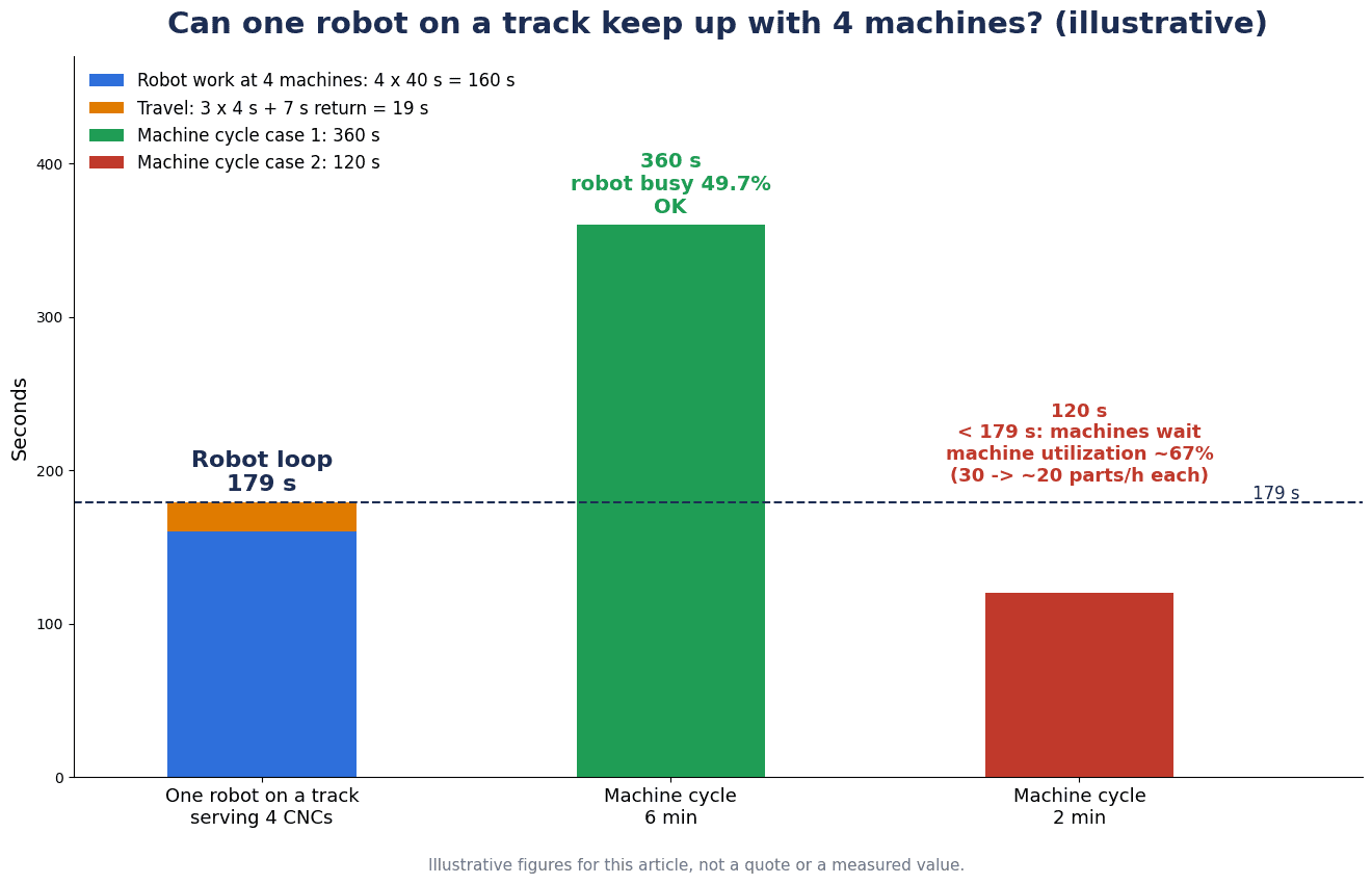
The assumed conditions are as follows.
- Robot work per machine (opening and closing the door, unloading and loading the workpiece, starting the machine): 40 s
- Travel to the next machine (3 m): 4 s. This value is set to allow for the catalog travel time for the specified distance plus settling; in practice, have the manufacturer provide the travel time for the specified distance
- Travel back from the 4th machine to the 1st (9 m): 7 s
The round-trip time is work of 40 s × 4 machines = 160 s plus travel of 4 s × 3 moves + 7 s = 19 s, for a total of 179 s.
| Machining cycle | Check | Result |
|---|---|---|
| 360 s (6 minutes) | 179 s < 360 s | Keeps up. Robot utilization is 179 ÷ 360 ≈ 49.7% (about 50%) |
| 120 s (2 minutes) | 179 s > 120 s | Cannot keep up. Each machine effectively produces 1 piece every 179 s, and machine utilization is 120 ÷ 179 ≈ about 67%. Instead of 30 pieces per hour per machine, output is about 20 |
With a 360 s machining cycle, the robot has about half its time to spare. With a 120 s cycle, on the other hand, the robot’s round becomes the bottleneck, and about one third of the machines’ capacity is lost to waiting. A design that shares one robot on a track works when the machine cycle is sufficiently longer than the robot’s round-trip time.
Another point not to forget is that when the one robot stops, all 4 machines stop. Every robot failure, gripper change, track greasing or cable inspection stops the whole line.
Calculation B: Initial cost and payback
For the same plant, we compare two options (all values hypothetical).
| Item | Option 1: 4 fixed robots | Option 2: 1 robot + track |
|---|---|---|
| Initial cost | Robot cell (one complete set) THB 2.5 million × 4 = THB 10.0 million | Robot cell THB 2.5 million + track, installation and safety fence addition THB 3.0 million = THB 5.5 million |
| Labor cost saved | THB 1,296,000/year | THB 1,296,000/year |
| Simple payback | 10.0 ÷ 1.296 ≈ about 7.7 years | 5.5 ÷ 1.296 ≈ about 4.2 years |
Option 2 has an initial cost THB 4.5 million, or 45%, lower than Option 1.
The labor cost saved is a placeholder common to both options. Assuming that with manual work one person attends to every 2 machines, that is 2 people per shift × 3 shifts = 6 people. With a labor cost of THB 18,000 per person per month (a placeholder including social security, overtime and allowances), 6 people × THB 18,000 × 12 months = THB 1,296,000/year.
For reference, the minimum wage in Chonburi Province is THB 400 per day (Wage Committee Notification “Minimum Wage Rates (No. 14)”, effective July 1, 2025). THB 400 × 26 days = THB 10,400/month, and the THB 18,000 in the calculation is a placeholder that adds social security, overtime and allowances to this. The minimum wage is the lower limit of the daily wage, not the total labor cost.
In this calculation, Option 2 looks cheaper and pays back sooner. However, that holds only when the cycle condition from Calculation A (the machine cycle is sufficiently longer than the 179 s round-trip time) is met. If many products have a 120 s machining cycle, Option 2 loses about one third of the machines’ capacity, and the options can no longer be compared on labor savings alone. In addition, Option 2 adds the risk of all 4 machines stopping at once when the robot stops, and the work of maintaining the track (lubrication, cables, rack). Do not decide on the difference in initial cost alone; judge together with the cycles of your product mix and how much stoppage impact you can tolerate.
Procurement and timing in Thailand
As opportunities to see actual equipment, JIMTOF2026 (the 33rd Japan International Machine Tool Fair) is scheduled to be held at Tokyo Big Sight from October 26 to 31, 2026 (during the show, East Halls 4 to 6 will be closed due to large-scale renovation work). In Thailand, METALEX 2026 is scheduled to be held at BITEC (Bangkok) from November 18 to 21, 2026. We have not checked in advance whether actual tracks will be exhibited, so please check the exhibitor information before visiting.
As investment support, the Thailand Board of Investment (BOI) has a “measure for improving efficiency through machinery upgrading and replacement and automation”. The 2025 Investment Promotion Guide covers the introduction of automation systems into existing production lines, listing import duty exemption on machinery and a 3-year corporate income tax exemption (capped at 50% of the improvement investment, with land costs and working capital not counted as investment), and states that the cap becomes 100% if linkage with or support for the Thai automation industry is 30% or more of the value of the improved machinery. The scope is investment in automation systems; it does not say that the purchase of a track on its own is covered. This is the content of the 2025 edition, and the current application status needs to be confirmed with the BOI. Please consult an expert on tax matters.
As for market trends, in World Robotics 2026, announced by the International Federation of Robotics (IFR) on September 24, 2026, annual installations of industrial robots worldwide rose 11% in 2025 to more than 600,000 units, and the operational stock reached a record 5 million units. The top 10 markets by installations include Singapore (4.6 thousand units, +26% year on year), but Thailand is not in the top 10.
Frequently Asked Questions
What is a robot track (7th axis, RTU)?
It is a device that mounts an articulated robot on a carriage and moves it in a straight line along a beam. Because it adds a 7th axis to a 6-axis robot, it is called the “7th axis”, and in English it is also called a Robot Transfer Unit (RTU), robot track, track motion, linear unit, and so on. It is used so that one robot can serve several machines or stations.
How should robot track payloads be compared?
They cannot be compared by a single number. Güdel’s TMF-2 lists “articulated robot 9,000 N” and “static load 25,000 N” for the same model, a gap of about 2.8 times. Winkel states the maximum emergency stop torque separately. For Yaskawa (European documents), ABB and KUKA, the documents do not define whether the payload includes the robot body. In the RFP, provide the mass of the robot body, gripper, workpiece and riser, and the maximum reaction forces including during emergency stop, and have the track manufacturer confirm that the track can handle them.
What repeatability do robot tracks offer?
In the manufacturers’ documents, KUKA KL 4000 and KL 250-3 and Güdel TMF-2, TMF-5 and TMO-2-W are stated as ±0.02 mm, ABB IRBT 2005 as ≤ ±0.05 mm, Yaskawa TSL (European documents) as ±0.05 to ±0.08 mm, and Winkel RLE as ±0.1 to ±0.2 mm. No document states the measurement conditions, so these cannot be used to compare which is better. Decide the required accuracy on the process side, and decide during selection whether any shortfall will be absorbed by vision or other compensation.
How do rack and pinion and belt drives differ?
In the documents reviewed for this article, rack and pinion is used for heavy robots. For Rollon’s aluminum-body RTU, the rack-and-pinion version is for “robots up to 1,500 kg”, and the open-belt and shielded-belt versions are for “payloads up to 20 kg”. Rollon explains that in environments with a lot of chips and spatter, a sealed (shielded) belt reduces internal contamination, and in clean environments an open belt can be more cost-effective (vendor claim).
Should a robot track be controlled as an external axis?
If the robot works while traveling (following a weld seam, etc.), a configuration synchronized as an external axis of the robot controller is suitable. If the track only moves between stations, a configuration driven by a separate servo, like OMRON’s track unit for the CRX, is also a candidate. Either way, a risk assessment before introduction is essential.
Should I choose floor mounting or overhead mounting?
Floor mounting is used for heavy robots and long strokes, while overhead and elevated mounting are options when you want to keep the floor in front of machines and forklift routes clear. Güdel describes ceiling mounting as “from directly above the work area, suited to processes accessed from above” and wall mounting as “suited to cases where building height is constrained”. Some products, such as the KUKA KL 4000 and Winkel RLE, are stated to support overhead mounting. Judge together with the building structure and access during maintenance.
How much does a robot track cost?
Our research did not find published prices from the manufacturers. The price of a track varies greatly with stroke, number of carriages, payload, mounting type, cables, covers, safety functions and the scope of installation work. Align the assumptions with the 12 RFP items, and have the breakdown (track itself, installation, floor reinforcement, cables, safety devices, commissioning) provided separately.
Summary
- A robot track cannot be selected only by asking whether the stroke and payload are sufficient
- Payload definitions differ between manufacturers. Güdel TMF-2 shows articulated robot 9,000 N / static load 25,000 N for the same model (about 2.8 times). Provide the mass of the robot body, gripper, workpiece and riser and the maximum reaction forces in the RFP
- Repeatability is “the value for that model in that document” with no measurement conditions. Decide the required accuracy, and decide first whether to absorb shortfalls with compensation
- For travel time, use the catalog value for the specified distance. For the Yaskawa TSL-1000 over 1,000 mm, calculation gives about 1.12 s, while the document gives 1.38 s
- Decide the drive (rack and pinion / belt), mounting type (floor, ceiling, wall, elevated frame) and control method (external axis / separate control) based on the application
- Floor foundation, cables, lubrication, covers, zero point and safety functions are easily overlooked on the track side. Read Güdel’s anchor table as the condition for Güdel products
- A design that shares one robot works when the machine cycle is sufficiently longer than the round-trip time. In the hypothetical calculation, against a 179 s round, a 360 s machining cycle works, while a 120 s cycle drops machine utilization to about 67%
- Align assumptions with the 12 RFP items, and measure accuracy, travel time, stopping distance, zero point and safety functions at the FAT/SAT
TOMAS TECH supports Japanese-affiliated plants in Thailand with the concept design of robot cells and peripheral equipment, specification organization, RFP preparation and witnessing of FAT/SAT. You are welcome to consult us even at the stage of checking whether a quote for a cell with a track is reasonable, or when you are just starting to prepare an RFP. Please contact us here.
References
- ISO 10218-1:2025 (ISO): https://committee.iso.org/standard/73933.html
- ISO 10218-2:2025 (ISO): https://committee.iso.org/standard/73934.html
- FANUC new robot product: Modular RTUs (August 2025, Japanese): https://www.fanuc.co.jp/ja/product/new_product/2025/202508_robot_modularrtus.html
- FANUC ROBOT New product: Modular RTUs (May 2024): https://www.fanuc.co.jp/en/product/new_product/2024/202405_robot_modularrtus.html
- Yaskawa Europe Track series (1089EN-01, October 2025): https://www.yaskawa.eu.com/_downloads/download_d2576
- Yaskawa Europe TSL-1000 (1077EN-01): https://www.yaskawa.eu.com/_downloads/download_d2577
- Yaskawa Europe TSL-2000, TSL-4000 (1078EN-04): https://www.yaskawa.eu.com/_downloads/download_d2578
- Yaskawa Europe TSL-600 (1081EN-01): https://www.yaskawa.eu.com/_downloads/download_d2579
- Yaskawa Europe TSL-1400 (1088EN-01): https://www.yaskawa.eu.com/_downloads/download_d21854
- Yaskawa Europe TS-100D (1076EN-03): https://www.yaskawa.eu.com/_downloads/download_d6835
- ABB IRBT 2005: Medium Track Platform Overview (November 2015): https://library.e.abb.com/public/2d196d1efac14abb9a3df6a1875844cb/External%20Product%20presentation%20IRBT2005%20_%20151116.pdf
- ABB IRT 510: https://www.abb.com/global/en/areas/robotics/products/equipment/track-motion-positioners/irt-510
- KUKA Linear Units: https://www.kuka.com/en-de/products/robot-systems/robot-periphery/linear-units
- KUKA KL 4000: https://www.kuka.com/en-de/products/robot-systems/robot-periphery/linear-units/kl-4000
- KUKA KL 250-3: https://www.kuka.com/en-de/products/robot-systems/robot-periphery/linear-units/kl-250-3
- Güdel TrackMotion Floor TMF: https://www.gudel.com/products/linear-tracks-for-robots/tmf
- Güdel TrackMotion Floor TMF-5 Factsheet (EN 08.26): https://gudel.cdn.kontainer.com/cdn-static/127d7796/wpjc5cmh7epy/factsheet-tmf-5-en.pdf
- Güdel Robotics catalog (May 2026 edition): https://gudel.cdn.kontainer.com/cdn-static/127d7796/DsM5p1Q1lQUy/260507-web-robotics-de-fr-en.pdf
- WINKEL RLE – Robot tracks: https://www.winkel.de/en/multi-axis-units/rle-robot-tracks
- Rollon Robot Transfer Unit (Aluminium): https://www.rollon.com/ind/en/family/robot-transfer-units/robot-transfer-unit/
- Rollon Steel RTU: https://www.rollon.com/ind/en/family/robot-transfer-units/steel-rtu/
- Rollon High Load Long Travel Linear Actuator Solutions for 7th Axis Robotics: https://www.rollon.com/ind/en/educationals/high-load-long-travel-linear-actuators-7th-axis-robotics/
- OMRON: Proposal for a track unit for FANUC CRX series collaborative robots (published by Daido, Japanese): https://www.daido-net.co.jp/exhibition/asset/pdf/2025/k-logi_2025/item03-1.pdf
- OSHA Technical Manual Section IV Chapter 4 Industrial Robot Systems and Industrial Robot System Safety: https://www.osha.gov/otm/section-4-safety-hazards/chapter-4
- Royal Thai Government Gazette: Wage Committee Notification on Minimum Wage Rates (No. 14): https://ratchakitcha.soc.go.th/documents/76681.pdf
- BOI Investment Promotion Guide 2025: https://osos.boi.go.th/download/BOI_PDF/BOI_A_Guide2025_EN.pdf
- IFR Five Million Robots now Operate in Factories Globally (Sep 24, 2026): https://ifr.org/ifr-press-releases/news/five-million-robots-now-operate-in-factories-globally
- IFR Market Presentation World Robotics Press Conference 2026: https://ifr.org/downloads/press_docs/Market_Presentation_WR_Press_Conference_2026.pdf
- METALEX 2026 official website: https://www.metalex.co.th/
- JIMTOF2026 outline: https://www.jimtof.org/jp/outline.html


