


When planning a mobile manipulator deployment, the first comparison should not be arm payload or maximum AMR speed. Success depends on whether the AMR can arrive at a defined pose, the arm can perform the task safely, the supervisory systems can trace both movements as one job, and the plant can recover from every abnormal condition through a predictable procedure. This guide is for buyers in Thailand factories considering a collaborative robot arm mounted on an AMR—often called a mobile manipulator, mobile cobot or AMMR. It focuses on docking and positioning, DC power, integrated safety, changing cell boundaries, MES/WMS interfaces, exception recovery, FAT/SAT, a 90-day proof of concept and contractual ownership.
The scope deliberately differs from our general guide to collaborative robot deployment, safety, TCO and RFPs and our engineering guide to conveyor-top AMRs. This article covers a compound machine whose base moves and whose arm performs physical work at multiple stations. The central question is not transport performance or a single fixed cell. It is who guarantees the boundary between navigation and manipulation.
Executive conclusion: procure one variable cell, not two products
Buying an AMR and a collaborative arm separately and connecting them on site does not create a production-ready mobile manipulator. The components may be physically mounted, but the application still needs explicit contractual answers to at least seven questions:
- In which coordinate system and within what verified tolerance is the AMR considered to have arrived?
- Which signals prevent automatic arm motion until the base is safely established?
- Who decides whether the base may travel when the arm is extended, holding a part or fitted with a changed tool?
- How will battery state, peak demand, idle demand and charging missions be managed across the base and robot controller?
- How will MES, WMS, fleet control, arm control, PLCs and process equipment use the same job identity and consistent states?
- Who owns recovery from a network loss, localization loss, bad docking, failed grasp, emergency stop or low battery?
- What measurements and records must be produced at FAT and SAT before the buyer accepts the system?
The procurement unit is therefore not “an AMR plus an arm.” It is a mobile cell that completes a specified job safely and repeatably. If the AMR manufacturer, robot supplier, system integrator and software vendor are different companies, the RFP still needs one prime party accountable for whole-system integration.
Why mobile manipulators matter in 2026
In its 3 September 2026 IMTS announcement, FANUC America introduced the portable CRX-3iA with a 3 kg payload and 11 kg mass. The same release described the R-50iA Compact DC Controller as designed specifically for CRX applications mounted on AMRs. FANUC states that it accepts direct 24–48 V DC battery power and can eliminate a separate inverter, reducing integration complexity. This announcement does not state a price, availability in Thailand or a general sale date, and this article does not infer any of them. It does show that low-mass arms and battery-direct controllers for mobile applications have become explicit product design priorities.
The official IMTS event page describes a CRX-3iA demonstration that senses its mounting angle and performs controlled vertical-up welding. It also describes a CRX-20iA/L demonstration that tracks moving parts and tightens bolts while they move. These are useful demonstrations of component capabilities. They are not proof that an autonomous base can travel through a live factory, dock at several machines and run unattended. Translating an exhibition capability into production requires new validation of docking, coordinate frames, workpiece variation, safety functions and recovery.
Mobile manipulator, mobile cobot and AMMR
The market uses mobile manipulator, mobile cobot, AMMR (autonomous mobile manipulation robot), and AMR with robot arm with overlapping meanings. Here, a mobile manipulator means a driverless mobile base integrated with an industrial robot arm, end effector, controller and safety equipment to perform physical tasks at more than one location. “Collaborative” does not automatically mean unguarded. The complete application—including the tool, workpiece, speed, force, surrounding machine and human access—requires task-specific risk reduction.
What changes compared with a transport AMR
A conveyor-top AMR is mainly governed by load geometry, transfer height, stops, sensors and a transfer handshake. A mobile manipulator adds an arm extending through three-dimensional space and interacting with doors, fixtures, parts and people.
| Design subject | Main issue for a conveyor-top AMR | Additional issue for a mobile manipulator |
|---|---|---|
| Position | Transfer height, lateral offset, load presence | Base pose in six degrees of freedom, tool-centre position and machine-coordinate transformation |
| Load | Weight and centre of gravity of transported goods | Changing centre of gravity by arm posture, reaction forces, overturning margin and cable loads |
| Safety | Driving and transfer pinch points | Overlap of travel and arm envelopes, dropped or ejected items and tool hazards |
| Power | Traction, conveyor and charging | Arm, controller, vision, vacuum and tool peak demand |
| Control | Transport request and transfer complete | State machine for jobs, docking, correction, work, inspection and recovery |
| Acceptance | Throughput and transfer success | Work quality, safe stops, positional repeatability and recovery from all exceptions |
Ignoring these additions creates compound failures: the AMR reports arrival but the arm cannot reach; simulation passes but the tool collides on the shop floor; or the battery percentage appears adequate while a transient tool-and-arm demand resets the controller.
Docking and positioning: build an error budget, not a catalogue comparison
AMR stopping accuracy is not tool-centre-point accuracy
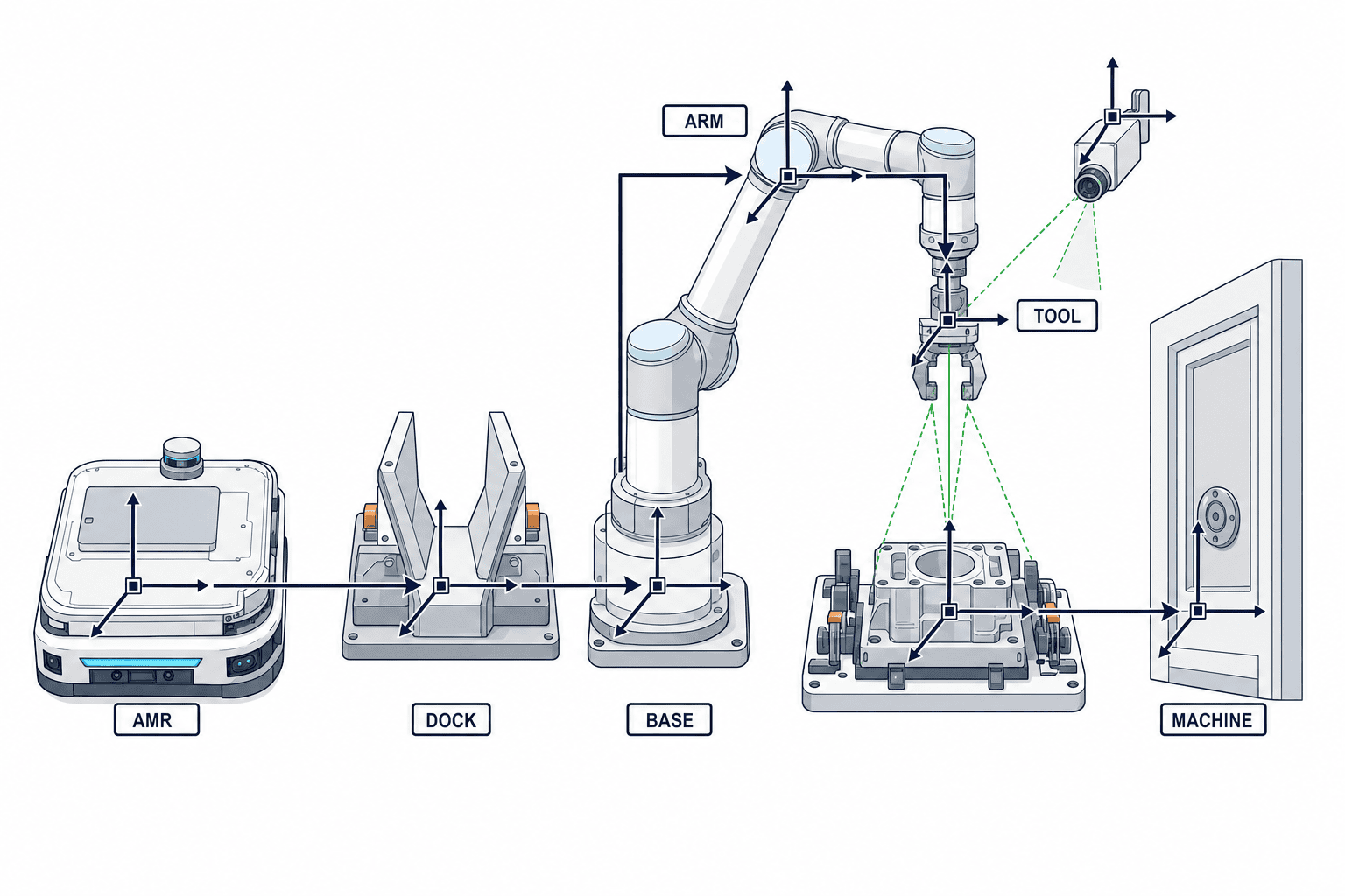
An RFP line that says “stopping accuracy ±X mm” leaves the real responsibility unresolved. The final tool position contains contributions from:
- AMR localization error on the map;
- floor unevenness, wheel wear and body attitude under load;
- clearance and repeatability of the mechanical dock;
- mounting error between the AMR deck and arm base;
- robot repeatability and absolute position error;
- tool changer, gripper and tool-centre tolerances;
- machine, fixture and workpiece variation;
- camera calibration, lighting, feature detection and frame transformation;
- temperature, vibration, cable reaction and gripping load.
A good stopping specification alone therefore does not prove a precision application. Start with process tolerance and allocate an error budget. Agree whether contributions are combined statistically, stacked as worst cases, or measured as a corrected end-to-end value. There is no universal number: the result depends on the process, equipment, floor and payload. Require the supplier to submit an error budget with test conditions and sample size.
Three levels of alignment
A practical architecture separates alignment into three levels:
- Coarse navigation: the AMR approaches the assigned station.
- Dock alignment: guides, pins, a target, LiDAR or vision reproduce the base pose.
- Workpoint correction: arm- or machine-mounted vision, touch sensing or force control locates the real fixture or part.
As precision becomes more demanding, a physical datum can reduce dependence on software correction. A mechanical dock also introduces new failure modes: failed release, trapped debris, bad lock confirmation and emergency manual release. The RFP must define not only what locks, but which movements remain inhibited if the lock is not proven.
Evidence that docking is valid
Do not allow a single “arrived” bit to authorize work. A typical set of conditions could include: the base is stopped, it is inside the assigned zone, the dock is locked, wheel drive is inhibited, the arm start condition is satisfied, the machine is ready, and safety inputs are healthy. This is an example of state logic, not a prescribed safety circuit. Safety-related controls must be designed and validated to the required performance identified by the risk assessment and applicable standards.
Battery and DC power: procure a power profile, not just capacity
FANUC America’s stated 24–48 V DC direct input for the R-50iA Compact DC Controller may reduce inverter hardware in a compatible CRX-on-AMR architecture. “Connects to DC,” however, is not a completed power design. Even where nominal voltages match, the project must verify peak current, regenerative energy, voltage sag, inrush, electromagnetic noise, bonding, protection, isolation, connectors and operation during charging.
| State | Base | Arm | Tool and peripherals | Required RFP evidence |
|---|---|---|---|---|
| Travel | Variable traction | Stopped or in a verified travel pose | Sensors active | Average/peak power, acceleration peak and permitted pose |
| Docking | Slow/stopped | Waiting | Vision and lock | Inrush, energy to lock, failed-dock behaviour |
| Work | Stationary | Trajectory-dependent | Gripper, vacuum, driver or inspection | Cycle waveform, peak, regeneration and quality effect |
| Idle | Stationary | Defined servo state | IPC and network | Standby power, wake time and safe state |
| Charge | Charger-dependent | Stopped or restricted | BMS and thermal control | Charge time, simultaneous-use rules, heat and charger count |
| Fault | Controlled stop | Control/safety stop | Alarm and logging | Residual energy, safe isolation and manual recovery |
Size the battery against the real mission sequence: travel, arm work at every station, waiting, congestion, movement to a charger, battery degradation, ambient conditions and reserve. Do not copy a generic “full-shift operation” claim into the business case. Recalculate with the plant’s profile, then capture power logs during the PoC.
Charging belongs in fleet capacity
Define what happens when energy crosses each threshold. Does the unit finish its current task, abort safely or hand the job to another unit? VDA 5050 v3.0 includes fields and actions relevant to energy and power-saving operation, but its scope is the communication interface between central fleet control and mobile robots. It does not guarantee safe arm stopping, process quality or machine restart. If VDA 5050 is used, the arm job and quality state still need an application-level model.
Mobile robot safety: do not bridge a standards gap with one certificate
Keep ISO 3691-4 and ISO 10218 scopes distinct
ISO 3691-4:2023 specifies safety requirements and verification for driverless industrial trucks and their systems; its official examples include AGVs and AMRs. ISO’s abstract describes the truck system as including control, guidance and power systems, while stating that requirements for the power source itself are outside the document. It also emphasizes that operating-zone conditions have a significant effect on safe operation. As of September 2026, ISO’s page says this edition is expected to be replaced by an ISO/DIS 3691-4 revision. A contract should freeze the applicable edition and allocate responsibility for assessing the final revision when published.
ISO 10218-1:2025 covers safety requirements for an industrial robot as partly completed machinery. ISO 10218-2:2025 covers integration, commissioning, operation, maintenance and decommissioning of industrial robot applications and robot cells. Crucially, the official scopes exclude “mobility” when robots or manipulators are integrated with driverless industrial trucks or mobile platforms. The arm and fixed application aspects can inform the safety specification, while the mobile-base side belongs in the driverless-truck domain; neither document alone closes every interface hazard of the compound machine.
The conclusion cannot be “an ISO 3691-4 AMR plus an ISO 10218 arm equals a safe mobile manipulator.” The integrator must assess combined hazards: interaction between travel and arm motion, a cell boundary that changes by location and state, human access that differs by station, workpiece or tool drop, shifting centre of gravity and coordinated emergency stopping.
A cell boundary is no longer a fixed line on the floor
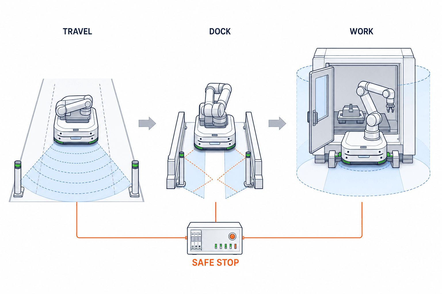
For a fixed robot cell, fencing and scanner fields can be anchored to one layout. For a mobile manipulator, the effective boundary changes by mode:
- Travelling: base contour, carried load, stowed arm, stopping distance and sensing field;
- Docking: pinch points between base and station, guide approach and locking mechanism;
- Working: arm reach, tool, workpiece, possible ejection and machine movement;
- Teaching/maintenance: human access, manual motion and energy isolation;
- Fault recovery: space for towing, pushing, brake release or lifting.
Do not compress these into one vague automatic/manual pair. Define permitted movement, speed, force, energy and access for each state. Examples include preventing travel unless the arm is in a verified transport pose, bringing arm motion to a safe stop if docking is lost, and preventing the base from departing while a machine door is open or a tool remains inside.
Emergency stop and protective stop boundaries
Create a matrix showing how the AMR emergency stops, arm emergency stop, machine emergency stop, scanners and doors affect each element and by which stop function. Cutting everything at once is not always the safest consequence: loss of vacuum can drop a part; a tool can remain in a machine; a vehicle can obstruct an evacuation or logistics aisle. Begin with risk reduction and residual-energy control, then design the authorized reset point, re-homing, work-in-progress disposition and restart checks.
Supervisory integration: bind travel, manipulation and quality to one job ID
If transport orders and robot programs are managed independently, the factory loses end-to-end traceability. Give the business job a unique ID and record at least these events in sequence:
- Job creation, priority, product and target machine;
- AMR assignment, route authorization, energy state and departure;
- Station arrival, dock request and dock proven;
- Machine ready, arm-program revision, tool ID and calibration state;
- Work detection, grasp and start/end of machining, fastening or inspection;
- Quality value, OK/NG, retry and quarantine destination;
- Undock, next destination and job completion;
- Fault code, state at occurrence, recovery action, person and downtime.
VDA 5050 v3.0 defines a vendor-neutral interface between central fleet control and mobile robots. Its 2026 update introduced capabilities for more autonomous vehicles, including zones, path sharing, translated error descriptions and power-saving operation. It is a useful candidate for mixed fleets. It is optional and does not standardize robot programs, torque results, vision inspection, machine interlocks or functional safety. An RFP should specify the VDA 5050 version, required topics and actions, retries, time synchronization, offline behaviour, extensions and conformance tests—not merely state “VDA 5050 compatible.”
Agree the state machine before the screens
Before designing dashboards, agree a state transition table. One project might use IDLE, ASSIGNED, NAVIGATING, DOCKING, READY, MANIPULATING, VERIFYING, UNDOCKING, COMPLETED, RECOVERY and SAFE_STOP. The labels are not important. Entry criteria, exit criteria, timeout, retry limit and owning system are. The design must detect split-brain conditions such as “base completed, arm running” or “MES cancelled, part still gripped.”
Design exception recovery first
A sales demonstration shows the normal path. Availability is usually determined by exception paths. Put fault-injection tests into the RFP and PoC.
| Exception | Expected automated response | Required plant procedure and evidence |
|---|---|---|
| Dock not proven | Retry only the allowed number, then retreat safely | Inspect debris, target and floor; preserve reason code |
| Part missing/double grasp | Do not start; reacquire or quarantine | Record part ID, image, grip signals and disposition |
| Network loss | Stop safely by state and prevent duplicate execution | Reconcile last committed event after reconnect |
| Low battery | Refuse new work and charge or transfer safely | Preserve energy history, charger state and job owner |
| Emergency stop | Stop the defined scope and control energy | Site check, reset authority, re-home and WIP decision |
| Machine alarm | Move to a safe pose where permitted and synchronize | Machine code, tool state and valid resume point |
| Localization loss | Prevent arm motion and stop travel | Relocalization, towing rule and aisle control |
| Quality NG | Limit rework and quarantine | Measurement, program revision, lot and approver |
“Operator to recover” is not a procedure. Define who uses which screen, what they verify, which device they reset, how they disposition the part, and which evidence they record. In Thailand, it is often practical to keep engineering screens in English while supplying Thai abnormal-response instructions, with both referencing the same state and fault codes.
A 90-day PoC that creates acceptance criteria
The schedule below is a project planning example, not a performance claim for a product. Adjust the days to the shutdown window, procurement lead time and required sample size.
Days 0–15: define the process and ownership
- Observe cycle, quality, stops, manual actions and abnormalities.
- Gather nominal, minimum, maximum, bad, dirty and displaced parts.
- Assign AMR, arm, tool, machine, IT/OT, safety and power roles in a RACI.
- Build a positioning error budget from process tolerance.
- List applicable standards and exclusions; name the owner of combined-risk integration.
Gate 1: should the resource be mobile? Compare one travelling robot with multiple fixed cells. Docking, travel, state switching and charging may cost more than the flexibility is worth.
Days 16–30: freeze interfaces and tests
- Review mechanics, centre of gravity, mounting, tooling, cables and maintenance access.
- Freeze I/O, APIs, job identity, state machine, time synchronization and logs.
- Write safety requirements, modes, zones and stop/restart matrix.
- Define power profile, BMS interface, isolation and charging mission.
- Agree FAT/SAT samples, repetitions, instruments, acceptance and retest rules.
Gate 2: is every claim testable? Replace “high accuracy,” “safe” and “seamless” with measurements or remove them.
Days 31–60: integrate one representative process
- Run navigation, docking, correction, work, inspection and undocking at one station.
- Test tolerance-edge, defective, dirty and lighting-variation samples.
- Record power waveform, energy state, thermal behaviour and charging.
- Safely reproduce interference from people, carts, doors and traffic.
- Trace all events under one job ID.
Gate 3: can the normal path repeat? Evaluate success rate, cycle distribution, correction magnitude, rework and interventions over an agreed sample—not a single video.
Days 61–75: inject faults and recover
- Inject network loss, obscured sensors, dock debris, low energy, machine alarms and missing parts.
- Test emergency stop, scanner entry and door opening, including restart.
- Confirm that logs reconstruct cause, affected part, software revision and recovery person.
- Measure recovery by trained staff using the Thai work instruction.
Gate 4: are stop and recovery acceptable? Separate unattended recovery from recovery requiring human authorization so automation does not create an unsafe restart.
Days 76–90: SAT-like run and scale decision
- Run with the real floor, network, parts, layout and shift.
- Have production, maintenance, EHS, IT and quality jointly disposition open points.
- Transfer spares, backups, source, licences, calibration and training.
- Separate reusable standards from station-specific items requiring reassessment.
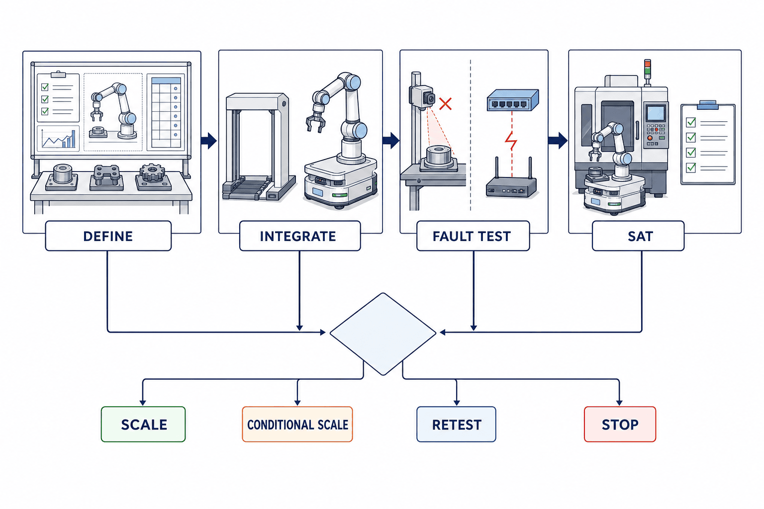
Gate 5: choose SCALE, CONDITIONAL SCALE, RETEST or STOP. A conditional decision must name each open point, owner, due date and affected scope.
FAT/SAT: buy evidence, not the statement “it moved”
FAT scope
FAT should verify the configuration and revisions, geometry, centre of gravity, mounting, wiring, power protection, I/O, APIs, state transitions, tool changes, calibration, representative parts, fault injection and safety-function records. Conditions that cannot be reproduced at the supplier—such as the final floor or wireless network—must be recorded as explicit SAT carryovers, not silently marked as passed.
SAT scope
SAT verifies site conditions: floor joints and slopes, reflective surfaces, dust, lighting, wireless roaming, aisle traffic, real machine coordinates, actual doors and fixtures, other vehicles, human routes, chargers and shift handover. Safety validation must leave evidence that the defined stopping and restart behaviour works under those site conditions.
Acceptance rules to make explicit
- units, instruments, calibration status and time synchronization;
- sample count, workpiece mix and exclusions;
- classification of first-pass success, success after retry, manual intervention and failure;
- safety items as non-compensable gates rather than average scores;
- regression scope after software changes;
- correction deadline, retest cost and delay responsibility;
- ownership of raw logs, videos, risk assessment and validation reports.
Mobile manipulator RFP responsibility matrix
| Work package | Name one accountable party | Required deliverable |
|---|---|---|
| Whole-system integration | Prime SI | System specification, responsibility matrix, integrated risk and acceptance closure |
| AMR and fleet | AMR supplier | Vehicle, map, traffic, charging, recovery, logs and API |
| Arm and controller | Robot SI | Base mounting, programs, safety functions and backups |
| EOAT and process | Process SI | Tool, part retention, quality, utilities and consumables |
| Docking | One integrated owner | Error budget, physical datum, proof, release and maintenance |
| Functional safety | Safety owner | Requirements, circuits, calculations, validation and residual risks |
| IT/OT integration | Integration owner | Jobs, states, history, time, retries and cybersecurity |
| Machine modification | Machine SI | Doors, fixture, PLC, interlocks and restart point |
| FAT/SAT | Buyer approves; SI executes | Procedure, data, evidence, correction and signatures |
| Operations handover | Factory and SI | SOPs, training, spares, maintenance and escalation |
The unowned middle is the main risk. Dock confirmation, arm start permission, travel restart permission, cross-system emergency stopping, power, clock alignment and log correlation frequently fall between vendors. A prime integrator does not need to manufacture every product, but must explain overall validity, coordinate subcontractors and close acceptance defects through one accountable interface.
Pre-order checklist
Process and business case
- Did you compare the mobile concept with multiple fixed cells?
- Is capacity calculated with travel, queue, dock, correction and charging time?
- Are benefits measurable beyond nominal headcount—quality, downtime, night operation and change flexibility?
- Can the project stop after PoC, and are scale conditions explicit?
Engineering
- Is there an error budget and correction method at every station?
- Are centre of gravity, overturning, travel pose and arm-stowed proof designed?
- Have peak current, protection, noise, regeneration and charging been checked—not only DC voltage?
- Can one job ID connect the order through the quality result?
- Can reconnect logic prevent duplicate execution?
Safety and operations
- Are ISO 3691-4 and ISO 10218-1/-2 scopes and exclusions understood?
- Is one party accountable for combined risks including mobility?
- Are boundaries defined for travel, docking, work, teaching, maintenance and recovery?
- Does testing cover part retention, machine state and restart after an emergency stop?
- Are Thai-language recovery instructions and competence checks included?
FAQ about mobile manipulator deployment
Are mobile manipulators and AMMRs the same?
They often overlap: AMMR usually means an autonomous mobile base integrated with a manipulator. Definitions vary by supplier. In an RFP, define navigation, arm, tool, safety modes, work envelope and interfaces instead of relying on the label.
Can an AMR with a collaborative arm operate without guarding?
Not automatically. Collaborative functions in the arm do not assess the hazards created by travel, the tool, workpiece, machine, human approach, dropping, trapping or a changing centre of gravity. The complete application requires risk assessment and appropriate protective measures for every location and mode.
What docking accuracy should we specify?
There is no universal number. Work backwards from allowable tool-centre error, then allocate AMR, dock, mounting, arm, tool, fixture, part and vision contributions. Specify the floor, load, temperature, sample count and corrected acceptance method, not only a catalogue value.
Does DC power remove the need for an inverter?
It depends on the selected controller. FANUC America states that its R-50iA Compact DC Controller supports direct 24–48 V DC battery power without a separate inverter. That statement applies to that product and does not generalize to every controller. Peak current, protection, bonding, regeneration, voltage sag and charging use remain project-specific.
Does VDA 5050 complete supervisory integration?
No. VDA 5050 chiefly defines communication between fleet control and mobile robots. Arm programs, machine PLCs, quality data, safety signals and manufacturing orders still need integration. State the VDA 5050 version and used feature set in the contract.
What should pass a 90-day PoC?
Do not judge only normal cycle time. Gate docking repeatability, work quality, power, network loss, localization loss, low battery, emergency stopping, machine faults, recovery time and log completeness. Derive values from the plant baseline and agree samples, instruments and retest rules in advance.
What is the most important RFP boundary?
The integration boundary between base and arm: dock proven, permission to manipulate, permission to resume travel, coordinated emergency stopping, power, logs and recovery. Assign one party to guarantee it. A stack of separate product warranties is not whole-system acceptance.
Summary: draw ownership before reach envelopes
A mobile manipulator can bring one flexible resource to several processes. The price of that flexibility is that positioning, energy, the safety boundary, software state and recovery responsibility move with it. Before comparing arm and AMR catalogues, create the error budget, power profile, state machine, safety requirements, fault tests, FAT/SAT evidence plan and RFP responsibility matrix. New products can widen the available architecture, but only measurable specifications and acceptance tests prove that the architecture works in your factory.
TOMAS TECH can support Thailand factories from site study and fixed-cell comparison through mobile-manipulator RFPs, AMR/arm/machine/IT ownership design, a 90-day PoC and FAT/SAT planning. You can contact us before selecting a product or vendor. Discuss your project with us.
References
- FANUC America, “FANUC America Brings Robotics, Automation, Physical AI and CNC Innovation to IMTS 2026,” 3 September 2026
- FANUC America, “IMTS 2026,” event page, 14–19 September 2026
- ISO 10218-1:2025, Robotics — Safety requirements — Part 1: Industrial robots
- ISO 10218-2:2025, Robotics — Safety requirements — Part 2: Industrial robot applications and robot cells
- ISO 3691-4:2023, Industrial trucks — Safety requirements and verification — Part 4: Driverless industrial trucks and their systems
- VDA, “Version 3.0 of VDA 5050 released,” 20 April 2026
- VDA 5050 Version 3.0.0, Interface for the Communication between Mobile Robots and a Fleet Control, March 2026
*The 90-day phases, state names and test items in this article are project-design examples. Confirm legal compliance and safety validation against the actual equipment, process, country and conditions with qualified specialists and the responsible integrator.*


