


When selecting a robot welding positioner, comparing its rated payload with the finished part weight is only the start. A fixture may push the actual load over the limit; a reachable seam may still require an unsuitable torch angle; a cell may stop the robot every time an operator loads a part. The real selection is a welding cell comprising the workpiece, fixture, robot, power source, operator and safeguards. This guide sets out the information a Thai manufacturer should prepare before requesting a quotation. Product figures below refer to specific models, not universal performance guarantees.
Define the workpiece before choosing equipment
A positioner rotates or tilts the workpiece to present a weld seam to the robot. ABB describes its workpiece positioners as equipment for manipulating parts in arc welding and cutting, with axes that can be coordinated with the robot. KUKA describes its two-axis positioner as a way to reorient complex or heavy workpieces repeatedly. Rotation alone is not the requirement: seam location, torch approach, wire and gas routing, loading direction and access for maintenance change with every position. ABB IRP B · KUKA KP2-HV
Identify at least three representative parts: the heaviest, the smallest and the most difficult shape. Record the mass and dimensions of the assembly as it will actually be welded, rather than only the finished product. Mark protrusions, possible center-of-gravity locations, locating surfaces, and the envelope swept during rotation. Include the fixture, clamps, adapters and any services mounted on the rotating side. A short compact part and a long frame of equal mass do not impose the same dynamic load. Record the loading posture too; it may differ from the welding posture.
What belongs on the first specification sheet?
List the part families, annual volume, shifts, welding process, seam lengths, material and thickness, joint types, target weld positions and acceptable inaccessible areas. Add changeover frequency and whether parts are removed while still hot. These data determine whether one or two axes are needed, whether a single or dual station makes sense, and whether the workpiece must move during welding or only between welds. Where several products share a cell, include how long exceptional parts occupy it. An average part is rarely a safe design basis by itself.
Check payload with the fixture included
Do not compare a catalogue payload with the bare workpiece alone. The rotating assembly can include the fixture, chuck, clamps, adapter, hardware associated with the welding-current return and auxiliary equipment. Definitions and conditions of rated load vary among products; send the complete load schedule to the supplier for assessment of each axis. ABB explicitly states that its IRP B range accommodates up to 750 kg including the fixture. KUKA lists a 500 kg rated payload for the KP2-HV500. These are model-specific examples, not a ranking of the two devices. Check the mounting conditions and limits in the relevant data sheet. ABB IRP B · KUKA KP2-HV500
Separate the workpiece mass, fixture mass and auxiliary rotating mass in your calculation. A 400 kg part, 120 kg fixture and 30 kg of chuck and accessories give 550 kg for assessment. That arithmetic example does not approve any particular machine: eccentricity, inertia, mounting, acceleration and axis orientation remain separate limits. State whether a lifting attachment remains on the rotating assembly. When the fixture is designed after the quotation, its mass often rises unexpectedly; a preliminary fixture design should therefore precede final machine selection.
Calculate center of gravity and inertia, not just mass
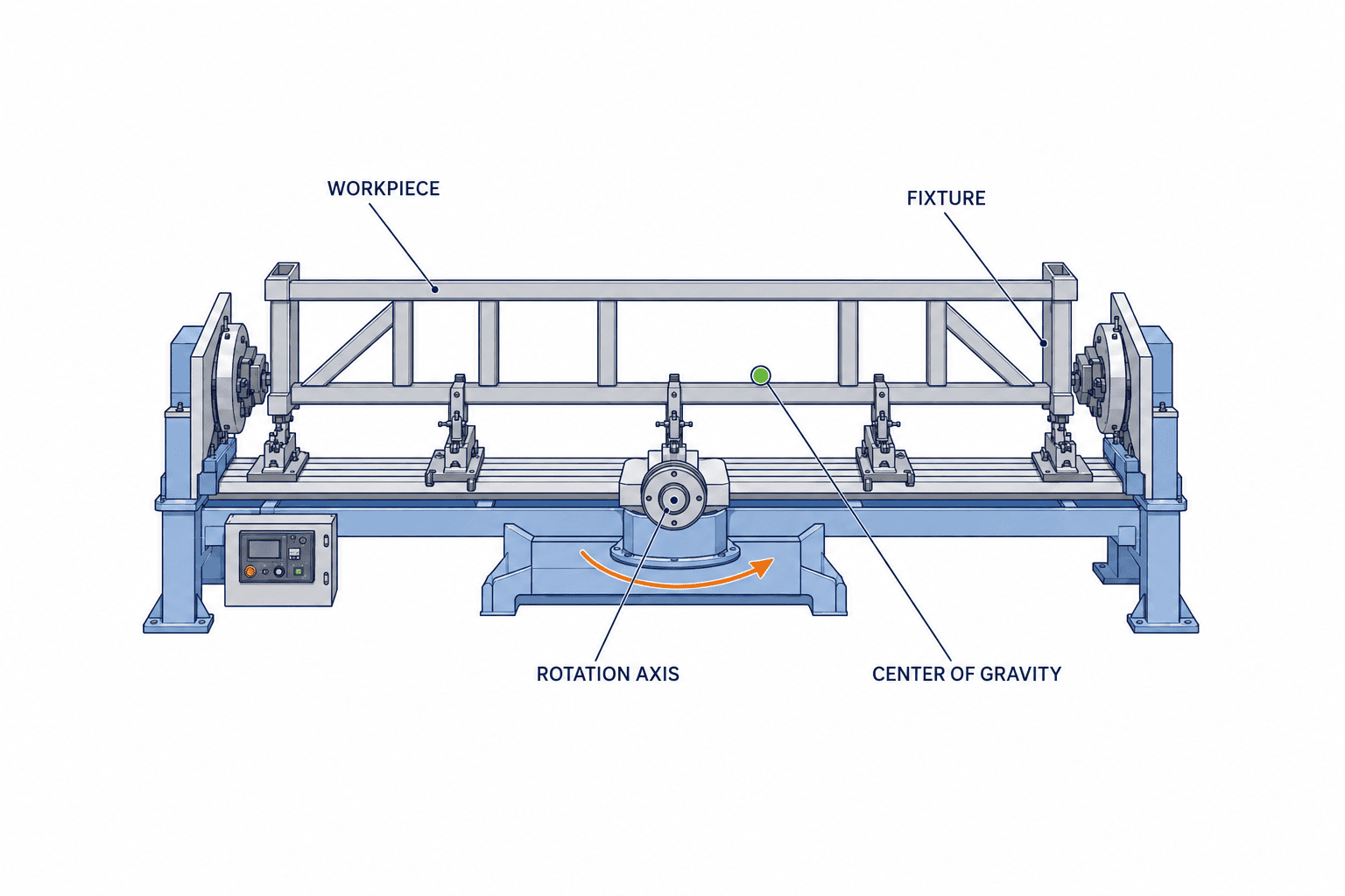
A compact 550 kg component close to the axis and a 550 kg long frame with mass concentrated at both ends need different acceleration and braking torque. Tilting adds gravity load that changes with angle. Supply center-of-gravity coordinates relative to each axis, mass moment of inertia, maximum eccentricity and the demanding load cases for each posture. CAD can provide estimates, but use the reference coordinate system and units requested by the manufacturer. ABB explains that its Load ID function calculates the center of gravity and inertia of the workpiece and fixture for dynamic control. ABB Workpiece Positioners
If drawings are unfinished, specify a range of possible centers of gravity rather than a falsely precise point. Assess the least favorable clamp arrangement and future variants. Being below rated mass does not establish suitability until allowable inertia and load torque are also checked. Give the vendor the intended start-stop cycle and duty pattern so thermal loading and brakes can be assessed. Measuring one prototype is useful, but it must not hide variation across production parts.
Choose between one axis, two axes and end-supported layouts
A single rotating axis may suit cylindrical parts or a simple component whose principal seams can be presented from one rotation. A box, construction-equipment part or complex bracket may need both rotation and tilt. A long frame may call for a headstock-and-tailstock arrangement. More axes can improve access, but they also add requirements for fixture design, cable management, programming and maintenance. Map representative seams against each proposed layout instead of assuming that two axes solve every access problem.
The KUKA KP2-HV500 is a two-axis positioner with a stated 500 kg rated payload and ±135° tilt range. KUKA offers other models and payloads, each with its own motion range and loading height. The useful question is whether the robot can approach each joint at the required angle without its arm, torch or cables striking a clamp. Verify that by simulation and then with a real part. KUKA product page · KUKA positioner data
State whether motion is indexed or continuous
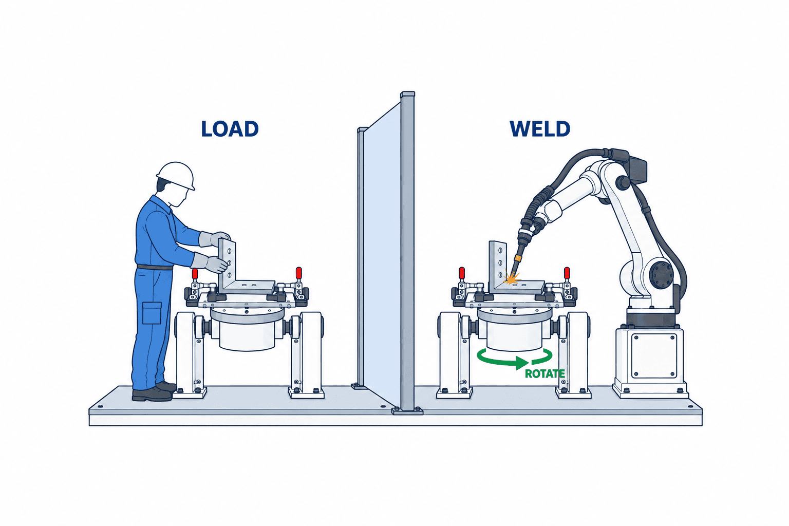
If the positioner moves to an angle and stops before welding, repeatable and safe indexing may be sufficient. If welding takes place while the part rotates, the robot tool-center-point path, seam speed and external-axis speed must work together. A two-station system can allow an operator to load on one side while the robot welds on the other, but it adds safeguarding and exchange-time requirements. ABB describes that twin-station arrangement for its IRP B. Never assume that another candidate has the same function. ABB IRP B
Verify robot reach at the required torch angle
Maximum robot reach does not tell you whether the torch can maintain the angle the weld needs. Consider wrist orientation, torch length, nozzle clearance, fixture projection and the wire-feed route. Tilting can bring one seam closer while moving another farther away. Study robot-base height, positioner center height and ergonomic loading height together. A floor plan alone misses protrusions that sweep above the work area.
The digital model should include the robot, torch, cables, positioner, maximum part envelope, every clamp, guarding and maintenance access. For each representative seam, check the start and end, posture change and escape location. A seam is not viable just because the robot tip can touch it; the welding process must still have a valid approach angle. See our robot welding implementation guide for wider cell planning and our robot gripper selection guide for locating and handling considerations.
Design locating, clamping and current return together
Positioner repeatability cannot correct a fixture with ambiguous datums. Decide which surfaces and pins locate the part, the clamp sequence, and how thermal expansion will be accommodated. A clamp in the torch path must be moved or the weld sequence changed. Tack weld location and amount influence how the joint shifts during final welding. If upstream part tolerances are wide, revisiting those processes and the fixture is more useful than trying to compensate entirely with robot teaching.
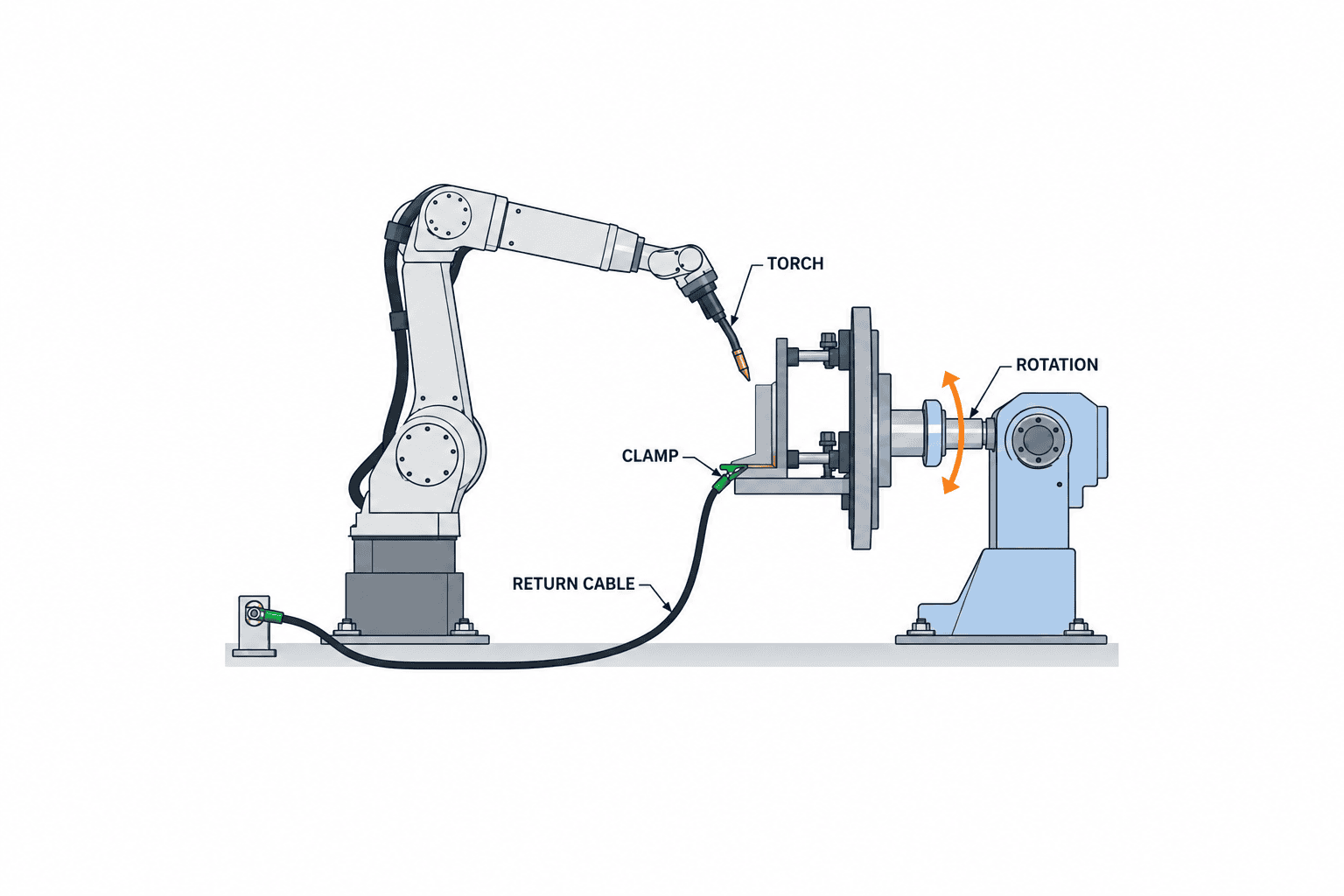
For arc welding, design the welding-current return so that current does not take an unintended path through a rotation axis or bearing. KUKA describes an insulated face plate and welding-current options for the KP2-HV500, but the correct return arrangement and current rating depend on the chosen equipment and process. Check twisting of power, gas and signal lines, spatter protection, replacement access and allowed rotation with the actual supply package. An axis described as continuously rotating may have a narrower range when an energy supply system is fitted. KUKA KP2-HV500
Confirm coordinated control and who owns the interfaces
Independent positioner control may work for indexed welding. Continuous welding on a moving part calls for compatible robot/external-axis coordination, calibration, teaching and recovery after a stop. Yaskawa’s YRC1000 instructions distinguish independent and coordinated control and include calibration between the manipulator and station. Ask the supplier to document the supported robot controller, axis count, software option and welding application; a verbal statement of “compatible” is too broad. Yaskawa Motoman coordinated-control instructions
Define what happens to the arc if the external axis stops, where the torch moves before homing, and how the load is held after power loss. When multiple vendors are involved, record responsibility for the robot, positioner, control cabinet, safety circuits and on-site service. Specify who maintains the digital model and the actual tool-center-point and work-coordinate data. Clear boundaries shorten troubleshooting after handover.
Calculate the entire cell cycle
Add loading, locating, clamping, checks, rotation, robot travel, arc time, cleaning, unloading, changeover and inspection. State which actions can overlap. If arc time is short but loading and clamping dominate, a faster rotation specification may yield little benefit compared with a better fixture and operator path. A long continuous weld raises other concerns: smooth coordinated motion, heat and cable routing. Check timing assumptions through measured current work or a representative trial.
Include yield and expected stoppages. Product change, torch cleaning, wire replacement, parts waiting and fixture spatter removal consume time that theoretical arc-time calculations omit. ABB notes that torch heat, spatter and collisions create a need for cleaning and tool-center-point checks. Decide which maintenance actions will be automatic and which require an operator. ABB Torch Service Center
Compare single and dual stations realistically
Loading on one side while welding on the other can overlap some tasks. Count station exchange, safeguarding reset, robot waiting and the actual loading sequence. A plan that depends on an operator rushing a clamp compromises safety and quality. Compare any saved time with the extra station, floor area, fixtures and maintenance. There is no universal “double productivity” factor.
Assess safety across the whole task cycle
Evaluate pinch points, falling loads, robot contact, arc light, spatter, heat, fumes and damaged services. Include loading, teaching, fixture change, cleaning, maintenance and fault recovery. The US OSHA robotics manual identifies welding fumes, heat, hazardous light, sparks and noise, and asks that hazards be assessed across lifecycle tasks, not only normal production. It is a useful primary source for hazard identification, not proof of compliance with Thai law. OSHA robotics safety manual
Guarding is more than choosing a fence or light curtain. Check stop time, reach distance, loading opening, reset authority and interlocks that prevent clamp release before the workpiece is safely held. Fume-capture effectiveness can change as the workpiece turns; assess all relevant postures. Local safety specialists and the supplier should verify current Thai requirements and applicable machine-safety standards. Include risk assessment, diagrams and safety-function validation records in acceptance documents.
Compare total installed cost
Compare the machine, fixtures, robot external-axis hardware and software, welding-current return, energy supply, guards, foundation, utilities, lifting equipment, commissioning, teaching, training and spare parts on the same scope. A simple included/excluded matrix often exposes the later cost of an apparently inexpensive offer. For a retrofit, check controller axis capacity, software version, cabinet space and existing safety circuits. Discovering an incompatibility late changes both cost and shutdown time.
The useful investment measure is total cost per good part, including rework, inspection, consumables, maintenance, fixture changes, staffing and records. Compare before and after using the same product mix and available hours. Count savings only for processes supported by a trial or measured baseline. Document exchange-rate and power-cost assumptions where they matter. Showing the uncertain assumptions is more useful than presenting a single payback figure without context.
Send a complete RFQ and agree acceptance criteria
Send the same revision of 3D data and drawings for the representative parts, estimated mass/center of gravity/inertia, fixture concept, weld seams and postures, target cycle, shifts, existing equipment, site layout, utilities and safety rules to each bidder. Explain anticipated product changes. Ask for the exact model, rated-load basis, allowable inertia and speed per axis, coordinated-control capability, cable rotation limits, maintenance parts and local support.
Before accepting the machine, test access to every representative seam, collisions through rotation, load cases, fixture repeatability, weld quality, cycle time, safety functions and recovery from power loss and abnormal stops. Agree the test parts, process settings, sample count and quality criteria before signing. Some products require dimensional or non-destructive inspection; align those criteria with quality engineering. A visible weld bead is not production acceptance. Include programs, backups, drawings, parts lists, maintenance procedures and operator training in the deliverables.
Review procurement in three stages
First, narrow the part family and check differences between drawings and actual parts. Wide variation from cutting, forming or tack welding cannot be cured by buying a more accurate positioner. Engineering, quality and production should agree which variation the fixture will absorb. Second, test motion on the proposed equipment. Check the smallest part’s clamps as well as maximum load, long-part deflection, torch escape behind the part and the return position after changeover. Digital models often omit the real wire and service bundle, so preserve a separate list for physical trials.
Third, review production operation: daily inspection, fixture cleaning, homing, alarm response and spare-part changes. Maintenance needs safe access to the drive. Production needs protection against installing the wrong fixture. Quality needs a way to associate welding conditions and inspection results with the correct part and lot. Settling these points before order reduces late changes during commissioning.
In the comparison table, make separate columns for load-center location, inertia, motion range, range with the service bundle, and coordinated welding. Check whether the buyer’s target cycle equals the supplier’s guaranteed cycle. Identify who provides trial parts, pays for factory and site acceptance tests, changes programs and responds to failures locally. Send the same unanswered questions to every bidder instead of guessing missing values.
Common selection failures and how to correct them
Sizing for the part alone: recalculate rotating mass, center of gravity and inertia with the fixture; compare fixture lightening with another machine. A reachable seam with a poor torch posture: repeat simulation with the required angle and clamp geometry. Cables winding around the axis: review travel, service supply and homing; discuss appropriate rotating connections with the supplier. Missing cycle target: measure non-arc waiting and improve loading or fixture action.
Variable seam location: inspect part datums, clamp order, fixture thermal effects, robot TCP and external-axis calibration before blaming robot accuracy. Slow restart: standardize a safe recovery path from each stopped position and train both maintenance and production leads. Record the process and equipment boundary at which each problem occurs; many failures involve interfaces rather than one defective component.
Selection scenarios by application
Circumferential welds on tanks and pipe
For cylindrical parts, align the rotation axis with the joint and maintain seam speed and torch posture. A simple outside circumference might use one axis; end faces or nozzles in the same cell may call for tilt. If the part is out of round, a centered fixture will not prevent the joint from moving vertically during rotation. Measure real joint geometry and define allowable gap and tracking method. With a long pipe supported at both ends, consider thermal expansion and fixture restraint. Continuous rotation also makes current return and service routing more demanding than stationary indexed welding.
Multi-face frames and brackets
Where short welds are distributed across several faces, robot travel and reorientation can exceed arc time. A two-axis machine may expose each face yet provide little value if clamps block the torch. For every seam, list preferred gravity direction, torch approach, nozzle clearance and whether it is reachable without moving the part. Count reorientations. Welding in a poor posture merely to save one movement may destabilize quality; process and quality engineers should agree priorities. The number of usable postures matters more than the catalogue motion range alone.
Heavy or long structures
Construction equipment and long frames raise questions of deflection between supports, uneven load and lifting posture as well as total mass. Compare cantilever with end-supported layouts and calculate floor loads. During rotation, a protrusion may approach fencing or the robot base. Guide the load during placement and prevent it from falling before clamping. If one fixture serves for lifting and welding, document when each device takes responsibility for supporting the load. Crane capacity and transport routes belong in the RFQ.
High mix versus high volume
For high-mix production, program recall, homing, fixture exchange and changeover safety may matter more than peak rotation speed. Fixtures sharing a mounting face need repeatable references and protection against wrong installation. In volume production, seconds per cycle and the frequency of cleaning or consumable changes both matter. Estimate benefits using annual hours per part family rather than one average product. Leave physical room for later second-station or material-handling expansion where justified, while evaluating the initial purchase on its own economics.
These are hypotheses for narrowing candidates, not fixed rules by product name. Joint and fixture geometry can change the answer. Verify the final candidate against real parts through load calculation, access checks and welding trials.
Confirm installation conditions at the Thai plant
Even a standard imported cell needs a site review. Overlay floor load capacity, anchor positions, floor level, aisles, overhead-crane or forklift access and neighboring equipment on the layout. Adequate positioner payload is irrelevant if the part cannot be placed safely. Include fume extraction, electrical capacity, compressed air, shielding gas, communications and maintenance isolation in the scope. Match actual plant temperature and environmental conditions to the manufacturer’s limits rather than assuming one protection rating fits every site.
For imported equipment, confirm who installs and commissions it, where parts will be stocked and who can attend a breakdown locally. Schedule foundation work, delivery, wiring, robot teaching, weld-parameter tuning, safety validation, quality approval and operator training separately. Delivery date is not production start date. Check local power and connectors, cabinet labeling and the languages of maintenance instructions so the site can support the equipment after handover.
Define normal questions, emergency support, spare-part orders and program changes separately in the service agreement. Record contacts, coverage hours, remote access requirements and the scope of site visits. If plant maintenance will replace cables or sensors, training should include tools, safe procedures and homing checks afterward. Availability depends on the recovery process as well as machine capability.
Also define change control after installation. Agree when a fixture modification, product revision, added weld or robot-program change requires renewed simulation and validation. A small added mass far from the rotation axis can have a disproportionate inertia effect. Update load calculations and safety assessment with the drawings so future staff can judge the approved operating envelope.
Keep measurements after production launch
For the first weeks, record loading-to-clamp time, robot waiting, external-axis movement, arc time, cleaning and unloading by product. When cycle time misses its target, this breakdown shows where to improve. Associate weld repairs, defect locations, fixture changes and alarms with the part number. Check part variation, torch wear and upstream delays before attributing every loss to the positioner.
Control product revisions. Compare any new part with the envelope, center-of-gravity and inertia ranges approved during design; request a new supplier assessment if it falls outside them. Similar-looking variants can be mounted in the wrong fixture, so consider locating pins and part identification. Build gear, brake, bearing, cable-wear, home-sensor and face-plate checks into maintenance according to the manufacturer’s instructions and actual usage. Separate operator start-of-shift checks from maintenance tasks and keep program and fixture revisions traceable.
Why trial and production parts need the same scrutiny
Prototype parts are often prepared carefully by experienced staff and may represent the best dimensions. Trial normal production parts, different loading operators, the lightest part and the longest part as well as the heaviest. If not every product can be tested fully, record why selected samples represent the range. Acceptance should use the product’s dimensional, penetration, defect, spatter, distortion and traceability criteria as relevant, not bead appearance alone. For a failed item, document the corrective owner, deadline and retest conditions. The goal is repeatable safe production of good parts under the agreed conditions.
Robot welding positioner FAQ
How much spare payload should a robot welding positioner have?
There is no universal percentage. Rated-load definitions, eccentricity, inertia, acceleration and duty conditions differ by model. Calculate all rotating mass, give the supplier center of gravity and inertia for each axis, and request a suitability decision for the intended cycle. State a conservative range for an unfinished fixture.
Is a one-axis or two-axis positioner better?
Choose the arrangement that presents the actual seams at a viable torch angle. One axis keeps a simple application simpler. Add tilt when a necessary seam otherwise remains inaccessible or poorly oriented. Validate representative parts with the robot and fixture included.
What does a welding positioner cost?
Total cost varies with load, axes, station count, fixtures, control integration, safeguarding and installation. Give bidders one common specification and compare identical scopes. A published payload figure cannot establish the installed cost.
Can a positioner be added to an existing welding robot?
Possibly, subject to controller external-axis support, coordinated-control options, licenses, axis capacity, power, wiring, safety and robot reach. Share the robot serial number, controller model, software version and cell drawings with the integrator.
Must the workpiece rotate while welding?
Only when the joint and quality requirements call for it. Some products can be indexed and welded at rest. For continuous circumferential welding, validate coordinated control, current return, service supply, torch posture and weld quality together.
Conclusion
A sound robot welding positioner selection checks payload, center of gravity, inertia, axes, robot access, fixture, control, cycle, safety and service against the same representative workpieces. Define seams first, calculate the whole rotating load, then verify the proposed cell by simulation and trial. That order makes quotations comparable and production acceptance measurable.
TOMAS TECH can help manufacturers in Thailand frame these requirements while a welding cell is still being planned. If you want to review a part drawing and target cycle before choosing a model, share an outline through our contact page.


