


When a Thailand factory introduces servo control, selecting equipment from rated power and maximum speed alone rarely produces a stable production system. The project must translate product motion, mechanical stiffness, cycle time, safety, upstream and downstream interfaces, and maintenance into one traceable specification. It must also define how those requirements will be accepted at FAT and SAT. This guide does not repeat a servo-versus-inverter comparison. It focuses on implementation: servo motor selection, a practical RFP, a gated 90-day proof of concept, tuning evidence, FAT/SAT, handover, and lifecycle cost.
Servo control projects succeed or fail before motor selection
Servo control closes the loop between a position, velocity, or torque command and measured motion. Yet the drive and motor are only two parts of the result. A ball screw, gearbox, coupling, frame, fixture, workpiece, sensor, PLC, industrial network, safety circuit, or recovery procedure can become the limiting factor.
Typical failures occur at interfaces rather than inside one component:
- The production workpiece becomes heavier than the sizing assumption, causing insufficient peak torque or regenerative capacity.
- Mechanical resonance sits close to the desired control bandwidth. Higher gain creates vibration, while lower gain lengthens settling time.
- PLC sequence states and motion-axis states do not align, so recovery after a fault is unpredictable.
- The RFP names STO or another safety function but does not define the hazardous situation, stopping behavior, restart condition, or validation method.
- FAT uses only a no-load demonstration, leaving real workpieces, full takt time, temperature rise, and continuous operation until SAT.
- Parameters and traces remain only on a commissioning engineer’s laptop, making later troubleshooting dependent on one person.
The starting question is therefore not “How many kilowatts?” It is: “Which workpiece must move along which path, within what time, accuracy, and safe-state conditions, and what evidence will prove acceptance?” Once that question is answered, competing SIer proposals can be compared on the same basis.
A six-layer architecture for a servo control system
Managing a servo project through a single electrical drawing hides the boundaries among mechanics, control, safety, and operations. Decomposing the project into six layers helps the owner identify missing requirements.
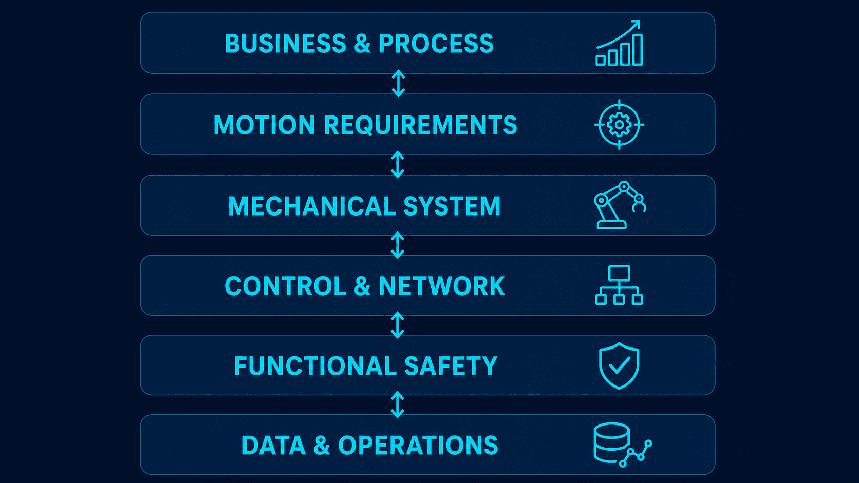
1. Business & Process
Define the manufacturing outcome: product families, good-part conditions, required output, changeover time, operating hours, future variants, and the cost of a stop. Replace “make it faster” with measurable language such as “complete the specified cycle for workpiece A within the agreed time” or “approve the first good part within the changeover target.” Measure variation and micro-stops, not only an average cycle time.
2. Motion Requirements
For every axis, specify travel, position, velocity, acceleration, jerk, dwell, synchronization, permissible following error, and repeatability. For an electronic cam or synchronized conveyor, define behavior when the master is lost, when the slave resynchronizes, and when phase is recovered after an emergency stop. A target without a measurement method is incomplete, so also specify instruments, sampling settings, and test conditions.
3. Mechanical System
Capture workpiece and fixture mass, center of gravity, load inertia, friction, gravity loads, transmission efficiency, gear ratio, backlash, stiffness, resonance, end stops, and physical travel limits. An adequately sized motor cannot compensate for every structural weakness. Coupling torsion, belt elasticity, frame deflection, or fixture play may dominate the settling result. For brownfield upgrades, measure the existing machine and record wear rather than trusting drawings alone.
4. Control & Network
Include the PLC, motion controller, drives, encoders, I/O, HMI, MES/SCADA connections, time synchronization, and network load. Avoid vague phrases such as “high-speed network.” State axis count, task cycles, tolerated delay, loss-of-communication behavior, restart conditions, and diagnostic ownership.
5. Functional Safety
Link hazards, operating modes, approach paths, protective measures, stopping functions, guards, interlocks, restart prevention, and validation records. Naming STO, SS1, or SLS is not a safety concept. The project must explain which risk each function addresses, in which operating mode, and how it interacts with a mechanical brake, a vertical load, and energy isolation.
6. Data & Operations
Define alarm history, trace files, recipes, backups, change logs, access rights, spare parts, training, remote support, and cybersecurity responsibilities. “Complete” should mean that the plant can investigate and recover after the original commissioning team has left.
Connect these layers with a requirement-design-test traceability matrix. A cycle-time change can then be traced through acceleration, peak torque, regenerative energy, structural vibration, safety distance, and data-sampling requirements.
Inputs for reliable servo motor selection
Servo motor selection is a motion-profile calculation, not an average-torque lookup. Yaskawa’s sizing guidance, as one manufacturer example, highlights torque, motion profile, load inertia, gearing, regeneration, and efficiency. The approach is useful, while actual allowable values must still come from the selected product and the real mechanical configuration.
| Area | Input | Result to review |
|---|---|---|
| Workpiece | Mass, center of gravity, orientation, variation | Minimum and maximum load cases |
| Motion | Distance, speed, acceleration, deceleration, jerk, dwell | Peak torque, RMS torque, settling |
| Transmission | Screw lead, pulley diameter, ratio, efficiency, backlash | Motor speed, reflected inertia, position loss |
| External force | Friction, gravity, press/process force | Continuous torque, holding and brake conditions |
| Regeneration | Deceleration frequency, vertical descent, common DC bus | Regenerative capacity and thermal behavior |
| Environment | Ambient/panel temperature, dust, oil, water, vibration | Derating, protection, cooling |
| Operation | Duty cycle, lifetime target, replacement time, spares | Bearing life, maintainability and inventory |
Put calculation assumptions into the RFP, not only final motor sizes. Friction, efficiency, maximum workpiece mass, and dwell time can materially change the result. Compare proposals by asking how each SIer evaluated peak torque, RMS torque, speed, regeneration, heat, and mechanical strength.
A practical project may examine three load cases: a representative product, a worst-case mass and friction case, and a foreseeable abnormal condition such as a near-jam. This is a recommended example, not a universal standard requirement. Use as many cases as the risk assessment and product range require.
Do not compress every margin into “30% spare capacity.” Peak torque, continuous torque, speed, regeneration, thermal capacity, mechanical strength, and supply capacity need separate checks. A larger motor is not automatically safer: additional rotor inertia may change response, enlarge the cabinet and power system, and increase mechanical impact.
Write a motion-control RFP as “performance plus evidence”
A strong RFP allows bidders to design from common assumptions and allows the owner to accept using common evidence. It should include:
- Current-process video, time study, stop history, and quality data.
- Product drawings, tolerances, mass range, and fixture constraints.
- Axis list and complete motion profiles.
- I/O list, sequence concept, and abnormal-recovery matrix.
- Cabinet, supply, grounding, network, and supervisory-system conditions.
- Risk-assessment scope, safety functions, and operating modes.
- FAT/SAT tests, acceptance criteria, evidence files, and signatories.
- Delivery terms for source code, parameters, licenses, and backups.
- Training language, support hours, local service, spares, and warranty.
- Price breakdown, exclusions, assumptions, and change-control rules.
Assign IDs to requirements. For example, MOT-AX03-012 can define an Axis 3 performance requirement, TST-FAT-021 its test, and EVD-TRACE-021 its trace file. When a criterion changes, the team can identify every design item and test that must be revisited.
The recovery-state principles in our sequence control design and FAT guide for Thailand also apply to motion. Define stop, resume, retry, manual intervention, communication loss, and power-cycle behavior. Review cabinet heat, power, grounding, noise, and service space with the control panel design guide for Thailand plants, because a motion design can be undermined by its panel environment.
Select an SIer by engineering evidence, not a brand logo
Even when bidders propose different brands, a requirement-response matrix creates a fair comparison.
| Evaluation | Question | Evidence |
|---|---|---|
| Requirement understanding | Which requirement is hardest, and which assumptions drive it? | Compliance matrix and open-item list |
| Engineering | How were torque, inertia, regeneration, and stiffness evaluated? | Calculations, simulation and bill of materials |
| Integration | Who owns PLC, motion, safety and supervisory interfaces? | Responsibility matrix, state model and network design |
| Verification | What will be measured, with which instruments, and how will pass/fail be decided? | FAT/SAT plan and sample report |
| Operations | Who responds locally in Thailand, and within what window? | Support roster, training and spare-parts plan |
Claims such as “AI predictive maintenance” or “automatic optimum tuning” should trigger questions about input data, applicable range, version control, and rollback. A successful demonstration is not the same as repeatable production. Ask bidders to explain a comparable failure, the evidence used to isolate it, and the permanent corrective action.
The owner should appoint mechanical, electrical, controls, IT, production, maintenance, and safety decision-makers. Even with a turnkey SIer, the plant still owns product conditions, site rules, acceptance decisions, and change approval.
What PLCopen Motion Control does—and does not—provide
PLCopen Motion Control organizes common function-block and axis-state concepts for motion applications. Shared ideas for power, homing, absolute/relative moves, and stopping can improve naming, review, and training.
PLCopen does not, by itself, guarantee identical behavior or full portability among PLC and drive platforms. Vendor extensions, library versions, parameters, error codes, task execution, buffering, cam functions, networks, and drive-resident functions still differ. The RFP should therefore state the library version, expected state transitions, exception behavior, restart behavior, and delivery of code and parameters—not merely “use PLCopen.”
Acceptance should cover interrupted moves, command conflicts, brief communication loss, axis faults, encoder faults, missing home state, and recovery after a safety stop. These cases expose implementation differences that a normal move cannot.
Derive STO, SS1, SLS, PL and SIL from risk assessment
Servo safety cannot be reduced to an STO checkbox. Use a risk-assessment process consistent with ISO 12100:2010 to identify machine limits, hazards, and risk-reduction measures. As of the article date in 2026, ISO 12100:2010 is the published edition and a revision is underway; confirm current status for each project.
ISO 13849-1:2023 may apply to safety-related control-system parts. IEC 60204-1:2016 with Amendment 1:2021 addresses electrical equipment of machines. IEC 61800-5-2:2016 addresses functional safety of safety-related power drive systems; the IEC page lists a 2026 stability date, which is not a claim that a new 2026 edition exists.
Applicable regulations and standards, the necessary PL or SIL, and validation methods depend on the machine, market, architecture, and risk assessment. This article cannot establish conformity or certification.
- STO (Safe Torque Off) prevents the drive from producing motor torque through its safety function. It is not the same as mechanical holding or complete electrical isolation.
- SS1 (Safe Stop 1) involves controlled deceleration followed by a safe state. Stopping time, behavior under fault, and final state must be designed.
- SLS (Safely-Limited Speed) safely monitors or limits speed and may support setup/maintenance modes when combined with other protective measures.
Omron’s product page provides a current product example including STO, SS1, and SLS; Siemens provides product examples for commissioning, diagnostics, and safety functions. These are examples, not universal system requirements. Required sensors, certification scope, response, wiring, parameters, and validation depend on the selected configuration.
On a vertical axis, STO may leave a gravity-drop hazard. Evaluate the mechanical brake, counterbalance, holding system, brake monitoring, and stopping distance together. Maintenance inside an enclosure may also require energy-isolation and lockout procedures beyond functional safety.
A 90-day PoC that removes uncertainty
The purpose of a PoC is not to run an impressive one-off demonstration. It is to reduce the largest technical and operational uncertainties before production investment. The following 90-day plan is a recommended project example, not a statutory or standards-mandated duration.

Gate 0, Days 0–10: Baseline and open items
Measure current cycle time, good-part rate, stop time, changeover, and quality variation. Confirm workpieces, fixtures, utilities, networks, safety scope, and data ownership. Establish requirement IDs and a risk register.
Gate 1, Days 11–30: Hardest axis and mechanical feasibility
Test maximum load, representative motion, worst settling, regeneration, thermal behavior, and resonance. Use a fixture that approximates real inertia, stiffness, and friction. If the target is missed, consider gearing, mechanics, trajectory, and fixtures—not tuning alone.
Gate 2, Days 31–55: Integrated cell
Integrate PLC sequence, multi-axis coordination, I/O, HMI, supervisory communication, alarms, and safety functions. Test missing parts, sensor conflicts, network loss, drive faults, emergency stops, and restart.
Gate 3, Days 56–75: Production trial
Run multiple product variants, high and low loads, sustained operation, changeovers, and different operators. Track quality, cycle, alarms, recovery time, parameter changes, temperature, and wear indicators. Some projects may use an eight-hour endurance test as a recommended example; the required duration should come from actual failure modes and production conditions.
Gate 4, Days 76–90: Production decision and handover plan
Close or classify unmet requirements, residual risk, production-design changes, cost deltas, FAT/SAT scope, training, spares, and support. Prototype code should be engineered for production with naming, error handling, permissions, backups, comments, and change history.
Close each gate when evidence is sufficient for a decision, not merely when a document has been submitted. A miss with a clear cause and next experiment may support a conditional go. A successful demo without traces or assumptions is weak investment evidence.
Servo tuning: preserve conditions, traces and rollback
Tuning may adjust position and velocity gains, filters, feedforward, vibration suppression, and friction compensation. Automatic tuning can be useful, but the requirement specification remains the acceptance reference. Save workpiece, fixture, temperature, lubrication, mechanical fasteners, firmware, profile, and measurement time with the parameter set.
Before reducing gain to silence vibration, inspect coupling tightness, alignment, frame stiffness, lubrication, interference, varying load, and encoder installation. Control parameters can temporarily hide a mechanical problem that returns with another product or after wear.
Do not accept on one representative trace. Compare low, normal, and highest required speeds; light and heavy loads; cold and warmed conditions; and both directions. Save position command, actual position, following error, velocity, torque/current, drive state, and alarms on the same time base. Trace sample rate and filter settings are part of the evidence.
A project might define “settling within 100 ms” or “overshoot below 5%,” but these are project examples, not universal requirements. The proper limits come from process quality, machine limits, and output needs.
Every production change should record the reason, person, axis, old value, new value, retest scope, approval, and rollback backup. A “small speed increase” can affect another product, regenerative capacity, mechanical life, and safety stopping distance.
FAT/SAT for servo control: accept with waveforms and evidence
FAT verifies what the builder can prove before shipment. SAT verifies the installed machine with actual utilities, surrounding equipment, products, and operating teams. Avoid repeating the same checklist. Use each environment to expose different risks.

FAT scope
- Part, drawing, software, parameter, firmware, and license consistency.
- Axis direction, home, coordinate units, software and hardware limits.
- Peak/RMS torque and tracking on representative and worst motion profiles.
- Automatic, manual, setup, stop, resume, and abnormal-recovery sequences.
- Communication loss, sensor fault, axis fault, and power-cycle behavior.
- Safety functions and validation evidence defined by the risk assessment.
- Alarm, trace, recipe, access-control, and backup functions.
- Draft drawings, bills of material, I/O lists, source code, and training material.
Additional SAT scope
- Actual power quality, grounding, noise, temperature, air, and interlocks.
- All product families, material variation, and full upstream/downstream cycle.
- Operator use, maintenance recovery, and supervisor change approval.
- Alarm frequency, minor stops, quality, following error, and thermal trend.
- Safe restart after emergency stop, guard opening, and manual intervention.
- Restore to a replacement drive or motor from the delivered backup.
- Final documentation, source, passwords, spares, warranty, and contact tree.
Minimum evidence pack
Each test should contain requirement ID, assumptions, procedure, instrument, acceptance criterion, result, decision, performer, date, evidence filename, and disposition of deviations. Preserve raw trace data and trace settings when possible, not only screenshots. Link videos to the tested product, load, and software version.
The following thresholds are project examples, not standards requirements:
| Test ID | Condition | Example decision | Evidence |
|---|---|---|---|
| FAT-MOT-01 | Maximum workpiece, 100 representative cycles | Agreed cycle and position-error limits; no protective stop | Position/velocity/torque traces and video |
| FAT-REC-02 | Highest required deceleration frequency | DC bus and regeneration remain within product limits | Drive trace and temperature log |
| FAT-ERR-03 | Simulated encoder/network fault | No hazardous motion; correct diagnosis and recovery | Event log, video and signed sheet |
| SAT-LINE-01 | Integrated line with real products | Agreed output, quality and stop-rate targets | Production log, quality data and alarms |
| SAT-REST-02 | Restore to replacement hardware | Restore and retest completed from instructions | Restore log, version list and signatures |
When a test fails, record cause, containment, permanent action, affected requirements, and retest scope. Do not turn an on-site adjustment directly into a pass without impact analysis.
Handover means the factory can recover
The handover package must transfer recovery capability, not just files on a USB drive.
Technical deliverables should include approved electrical/mechanical drawings, cabinet layout, BOM, cables, I/O, buildable PLC/motion/HMI/safety projects, axis parameters, baseline traces, firmware and library compatibility, network and time-sync design, access rights, backups, risk assessment, safety verification, FAT/SAT records, open items, and change history.
Operational deliverables should include operator setup and recovery, maintenance fault isolation, replacement and re-homing procedures, inspection and lubrication schedules, critical-spare quantities and lead times, local Thailand escalation contacts, backup frequency, change governance, and cybersecurity update ownership.
Use a teach-back test: a plant maintenance technician follows the document to diagnose a simulated fault, restore a backup, and return the axis to a verified state. If the SIer performs every action, capability has not yet been transferred. Define whether training and interface terminology must be available in Thai, English, or Japanese.
TCO: include downtime, engineering and future changes
The purchase price of motors and drives is only one part of total cost of ownership. Include requirement engineering, mechanics, cabinet modification, wiring, network, safety, software, commissioning, production downtime, training, spares, licenses, support, and future product changes.
An illustrative model is:
TCO = equipment + engineering + installation downtime + lifecycle maintenance/spares/licenses + future variant work + expected failure downtime − production/quality/labor benefits
The horizon—five years, for example—is a project choice, not a standard. Use optimistic, base, and downside cases. Verify that a faster axis actually improves the line bottleneck.
Hidden cost drivers include the loss per hour of downtime, emergency import lead time, dependency on one engineer, software subscriptions, and migration from obsolete products. A lower purchase price can produce higher TCO when a replacement is unavailable in Thailand. A feature-rich platform can also be poor value if unused capabilities add licenses and training.
Check Thailand BOI eligibility before committing
Thailand BOI’s public Smart and Sustainable Industry information describes a THB 1 million minimum investment, machinery import-duty exemption, and a three-year corporate-income-tax exemption equal to 50% of the investment. It also describes 100% of investment where linkage to domestic automation-system integration is at least 30%. Eligibility, qualifying expenditure, timing, and domestic-linkage calculation must be confirmed directly with BOI or qualified advisers before procurement. Do not build a business case on an assumed incentive.
BOI reported 132 Smart and Sustainable Industry projects totaling THB 17.158 billion in the first half of 2026. This provides market context, not proof that a particular servo project will qualify or achieve payback.
Data integration: start with diagnosability
Servo systems can expose following error, torque, temperature, operating time, alarms, and load changes. Availability, sample rate, accuracy, synchronization, and retention differ by product and architecture. Continuous cloud streaming of high-frequency traces may be less useful than event-triggered capture at the drive or edge with summarized data upstream.
The first value is often diagnosability rather than an AI prediction model. Align PLC events, drive traces, sensors, quality results, and operator actions on one time base and tag equipment, product, recipe, and software version.
In June 2026, OPC Foundation material described OPC UA FX Controller-to-Device motion work as release-candidate/prototyping activity. It is an important direction, but it should not be represented as universally completed or generally available. Validate the current products, performance, diagnostics, and safety boundaries for the actual project; treat future interoperability as an option.
Owner’s final checklist
Before RFP
- [ ] Baseline cycle, stops, quality, and changeover are measured.
- [ ] Product mass, tolerance, variants, and future cases are documented.
- [ ] Every axis has a motion profile and synchronization definition.
- [ ] Torque, inertia, regeneration, thermal and mechanical assumptions are traceable.
- [ ] Fault recovery and power-cycle states are specified.
- [ ] Safety scope, applicable standards, and validation ownership are assigned.
- [ ] FAT/SAT criteria and evidence formats are part of the RFP.
- [ ] Source, parameters, licenses, training and spares have delivery terms.
During design and PoC
- [ ] Requirement-to-design-to-test traceability is current.
- [ ] Worst load, real stiffness, friction and product variation are tested.
- [ ] Before/after tuning traces and conditions are retained.
- [ ] Open items, changes and residual risks receive weekly decisions.
- [ ] Motion, sequence, safety and data interfaces are tested together.
- [ ] Stop/redesign criteria are used, not only success criteria.
FAT/SAT and handover
- [ ] Every pass has measured data, raw evidence and signatures.
- [ ] All variants, maximum load, endurance and recovery are covered.
- [ ] Retest scope after a change is documented.
- [ ] Final projects and parameters can be restored on another PC.
- [ ] Maintenance completes a teach-back recovery.
- [ ] Local support, spares, warranty and escalation are agreed.
FAQ about servo motor selection, tuning and FAT/SAT
What is servo control?
It is closed-loop control that corrects the difference between commanded and measured position, speed, or torque. The appropriate architecture depends on the process; servo is not automatically the best choice for every variable-speed application.
What information is needed first for servo motor selection?
Start with a time-based motion profile, product and fixture mass, inertia, transmission, friction, efficiency, gravity, regeneration, environment, and duty cycle. Use measured current-machine data where possible and include worst product conditions.
Should a motion-control RFP specify a brand?
A brand standard can be reasonable for spares, training, or existing architecture, but it should not replace performance, safety, interface, evidence, and handover requirements.
Is automatic tuning enough for servo commissioning?
No. It is a useful starting tool. Validate with real products across load, speed, direction, temperature, and recovery conditions, and preserve the associated traces and configuration.
How should servo FAT and SAT differ?
FAT should deeply test what is reproducible before shipment: build, software, motion, safety, diagnostics, and faults. SAT adds actual power, grounding, surrounding machines, real products, operators, sustained production, and backup recovery.
Does STO make a machine compliant?
No. STO is one safety function. The complete risk-reduction architecture, required PL/SIL, sensors, logic, actuators, mechanics, wiring, and validation come from the risk assessment and applicable requirements.
What is a good pass criterion for a 90-day PoC?
Pass when evidence resolves the most important risks and supports a production cost and residual-risk decision. Ninety days and the described gates are project examples, so adjust them to the machine and validation scope.
Does PLCopen guarantee easy migration between vendors?
No. Common concepts support standardization, but libraries, states, faults, tasks, drive features, networks, and extensions still require verification and migration testing.
Can a Thailand servo project receive BOI incentives?
It may be eligible under relevant activities and conditions, but BOI must confirm the specific project, expenditure, timing, and local-integration criteria. Prepare a TCO case that also works without the incentive.
Conclusion: connect requirements, evidence and recovery
A robust servo control project starts with production outcomes and measurable motion requirements, then connects mechanics, control, network, safety, data, and operations. Motor selection must include the complete profile, inertia, regeneration, and thermal behavior. The RFP must define acceptance evidence and delivery terms. A gated PoC removes uncertainty, FAT/SAT preserves waveforms and decisions, and handover ends only when plant maintenance can diagnose and restore the system.
If your Thailand plant is considering a new servo axis, a brownfield upgrade, an RFP, sizing review, or FAT/SAT plan, TOMAS TECH can support the project from the concept stage. We connect mechanical, controls, safety, data, and local maintenance requirements without requiring you to have a final specification first. Contact TOMAS TECH.
References
- PLCopen, Motion Control: https://www.plcopen.org/standards/motion-control/
- PLCopen Motion Control Part 1 Version 2.0: https://plcopen.org/system/files/downloads/plcopen_motion_control_part_1_version_2.0.pdf
- IEC 61800-5-2:2016: https://webstore.iec.ch/en/publication/24556
- ISO 13849-1:2023: https://www.iso.org/standard/73481.html
- IEC 60204-1:2016/AMD1:2021: https://webstore.iec.ch/en/publication/66124
- ISO 12100:2010: https://www.iso.org/standard/51528.html
- Yaskawa, Servo Sizing: https://www.yaskawa.com/downloads/search-index/details?docnum=eLM.Servo.03.Sizing2&showType=details
- Omron product example: https://www.ia.omron.com/products/family/3923/feature.html
- Siemens drive software examples: https://www.siemens.com/en-us/products/sinamics/drive-software/
- Thailand BOI, Smart and Sustainable Industry: https://www.boi.go.th/index.php?language=en&page=smart_sustainable
- Thailand BOI, 1H2026 update: https://www.boi.go.th/un/boi_event_detail?language=th&module=news&topic_id=139075
- OPC Foundation, OPC UA FX C2D motion update: https://opcconnect.opcfoundation.org/2026/06/field-level-communications-corner-june-2026/
*Unless explicitly identified otherwise, numerical thresholds, test durations, capacity margins and gate timings in this article are recommended or project examples. They are not universal legal or standards requirements. Confirm safety functions, PL/SIL, conformity, and BOI eligibility against the actual machine, current official requirements, and competent authorities.*


