



The drawing from the machine builder says only “Linear guide, Company XX, Model XX.” The quotation comparison sheet lists each maker’s basic dynamic load rating C, and the larger number looks as if it will last longer. In linear guide selection, however, this way of comparing has a weak spot. Depending on the manufacturer, the basic dynamic load rating C is given either as “the value for 50 km of travel” or as “the value for 100 km of travel,” and the two are mixed. Even when two catalogs both say 20,000 N, a different rating distance makes the calculated life appear to differ by a factor of about 2.
This article makes one argument. Linear guide selection does not start with “comparing catalog numbers.” It starts with “making sure the calculations use the same manufacturer’s definitions.” Not only the basic dynamic load rating C, but also the recommended values for the static safety factor, the preload symbols and the accuracy class symbols have different bases or meanings from one manufacturer to another. For that reason, the buyer should put the following 3 items into the RFP (request for proposal).
- Have the calculation sheet state the manufacturer definitions and factors used (rating distance, load factor, source of the recommended values)
- Specify preload and accuracy in words and quantities, not symbols, and decide them together with the accuracy of the mounting surfaces
- Eliminate the main causes of premature damage (mounting errors, insufficient lubrication, contamination, handling) through FAT/SAT and the maintenance plan
Below, for production engineering, machine design, maintenance and procurement staff who design or order automated machines, inspection equipment, conveying equipment and jigs at Japanese plants in Thailand (and ASEAN), we cover, in order: the construction of linear guides, the 7 selection steps, loads and moments, the static safety factor, life calculation, preload and rigidity, accuracy classes and mounting surfaces, environmental measures, premature damage, the RFP, FAT/SAT, and procurement in Thailand. Ball screws on the feed-drive side are covered in “Ball Screw Selection for Thailand: RFP and FAT/SAT Guide,” so this article focuses on the “guide that supports the machine’s linear axis” itself. The figures in the model calculations in this article are not values for any specific product or model number; they are hypothetical figures placed to show the structure and sensitivity of the calculation.
Why “Comparing Catalogs” Is Risky in Linear Guide Selection
The rating distance is split between 50 km and 100 km
Linear guide life is calculated from the ratio of the basic dynamic load rating C to the load P acting on the block. The definition of this C differs from manufacturer to manufacturer.
- THK (LM Guide) and HIWIN (Linear Guideway) define C for ball types on a 50 km rating distance and C for roller types on a 100 km rating distance.
- NSK (the NH/NS series catalog) lists both C50 on a 50 km basis and C100 on a 100 km basis in its dimension tables.
- Bosch Rexroth (the Ball Rail Systems catalog) states that, in accordance with DIN ISO 14728-1, it determines dynamic load ratings on the basis of 100 km of travel even for ball types, and writes that C, Mt and ML should be multiplied by 1.26 when comparing with values on a 50 km basis.
THK itself writes that, when comparing nominal life, one should take into account whether C is on a 50 km or 100 km basis and, if necessary, convert based on ISO 14728-1. In other words, simply lining up catalog C values side by side can mean comparing numbers obtained under different conditions. Always include a “rating distance of the C value” column in the comparison sheet and the RFP.
2026 product news also calls for “checking the definitions”
There were several product announcements around linear motion guides in 2026.
- On July 23, 2026, THK announced, through its European subsidiary (THK GmbH), the “GK Series” of standard-dimension LM Guides compliant with ISO 12090-1 and ISO 12090-2. According to THK, blocks and rails are supplied separately from stock with short lead times and are interchangeable within the range of series, accuracy class (up to Precision grade) and preload category. The covered models are HSR, SR, SHS, SSR, HDR and the roller guides SRG and HRX (compliant with ISO 12090-1), and the miniature RSX and SRS (compliant with ISO 12090-2). This is a manufacturer announcement, and it does not describe the launch or stock arrangements in ASEAN, including Thailand.
- On October 1, 2026, IKO (Nippon Thompson) launched the LRXD8…SL, the smallest size of the Linear Roller Way Super X. According to the company’s announcement, it is 11 mm high and 16 mm wide, uses stainless steel for the rail, slide unit and rollers, and its main intended applications are production and inspection equipment, medical equipment and, in particular, semiconductor manufacturing equipment. On the same day, the company also launched the NT100V25, the smallest size of the Linear Motor Table NT100V series.
- JIMTOF2026 (the 33rd Japan International Machine Tool Fair) is scheduled to be held at Tokyo Big Sight from October 26 to 31, and the organizer’s September 28 announcement states that 1,134 companies (4,422 booths) from 22 countries and regions will exhibit. In Bangkok, METALEX 2026 is scheduled to be held at BITEC from November 18 to 21.
Even for products that claim interchangeability, the scope of interchangeability (up to which accuracy class, up to which preload category) applies only within conditions set by the manufacturer. The interchangeability of the GK Series is also, according to THK, “up to Precision grade.” When evaluating new products, the procedure of checking the rating distance of C, the accuracy class and the preload definition in that manufacturer’s own documents does not change.
What Is a Linear Guide: Construction, Names, Ball Type and Roller Type
Components
A linear guide consists of a rail (track rail) with a straight raceway, a block running on it (also called a slider, carriage or slide unit), rolling elements (balls or rollers) circulating inside the block, and seals that keep out foreign matter and retain the lubricant. Because the rolling elements roll, the guide can be moved with less force than a sliding guide. In its technical documentation, HIWIN gives the friction coefficient as about 0.004 for ball types and about 0.003 for roller types, and explains that this can be about 1/50 of a conventional sliding guide.
Names differ by manufacturer
Even for the same kind of component, the name differs by manufacturer.
| Manufacturer | Product name |
|---|---|
| THK | LM Guide |
| HIWIN | Linear Guideway |
| NSK | Linear Guides |
| Bosch Rexroth | Ball Rail Systems |
| IKO (Nippon Thompson) | Linear Way / Linear Roller Way |
The ISO term is “linear motion rolling bearings,” which the Japan Bearing Industry Association (JBIA) translates into Japanese as “linear bearings.” Even when drawings and specifications use a manufacturer’s proprietary name, they often refer to the same kind of component, so standardizing the terminology within the company reduces confusion.
Differences between ball type and roller type
| Item | Ball type | Roller type | Source |
|---|---|---|---|
| Exponent in the life formula | 3 | 10/3 | HIWIN technical information |
| Rating distance of C | 50 km | 100 km | THK, HIWIN |
| Guideline friction coefficient | About 0.004 | About 0.003 | HIWIN technical information |
In its announcement of the LRXD8…SL, IKO explains that “because the rolling elements are rollers, the amount of elastic deformation under load is smaller than with balls.” This is the manufacturer’s explanation. Note also that, as mentioned above, Bosch Rexroth’s ball type catalog uses a 100 km basis, so it cannot be said that “ball types are always 50 km.” Check the definition of the manufacturer you adopt individually.
Standards: ISO 14728-1/-2 and the correspondence with JIS
The method for calculating load ratings and life of linear guides is specified in ISO 14728.
- ISO 14728-1:2017 (Part 1: Dynamic load ratings and rating life): the 2nd edition, published in February 2017, and reviewed and confirmed in 2022. It specifies the calculation methods for the basic dynamic load rating and the basic rating life. The ISO abstract states that it does not apply to designs in which the rolling elements roll directly on a machine’s sliding surface, unless that surface is fully equivalent to the raceway of a linear bearing.
- ISO 14728-2:2017 (Part 2: Static load ratings): likewise the 2nd edition, published in February 2017, and reviewed and confirmed in 2022. It specifies the calculation methods for the basic static load rating, the static equivalent load and the static safety factor.
According to the commentary by the JBIA linear bearing subcommittee, the 1st edition of ISO 14728 was published in June 2004, and the main changes in the 2nd edition of 2017 were an updated format, changes in the handling of referenced standards, partial changes to the load direction figures and correction of errors. It does not say that the calculation system changed significantly.
What needs attention is the correspondence with JIS. In the JBIA list of “ISO standards related to rolling bearings” (as of June 2026), the “related JIS” column for ISO 14728-1 and ISO 14728-2 is blank. In the same list, JIS B 1518 is matched to ISO 281 and JIS B 1519 to ISO 76 for rotary bearings, but these are rotary bearing standards. Also, JIS B 1192-5:2018 is “Ball screws – Part 5: Static and dynamic axial load ratings and operational life,” a ball screw standard. When writing “JIS compliant” in a specification, state specifically which part of which standard is meant, and do not apply JIS numbers for rotary bearings or ball screws to linear guides.
The 7 Steps of Linear Guide Selection
The Bosch Rexroth catalog (which states that it is based on DIN 637), HIWIN’s technical information and THK’s selection pages all present a selection flow. The order differs slightly, but the common skeleton starts from the operating conditions and proceeds through loads, static safety factor, life, rigidity (preload), accuracy and environment. This article organizes it into 7 steps and finally connects it to the RFP and FAT/SAT.
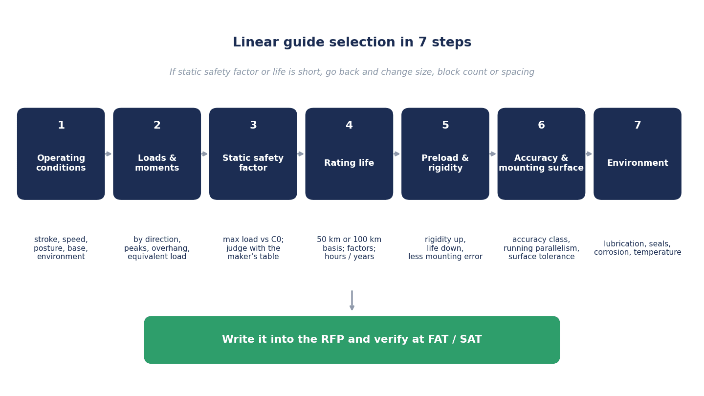
| Step | What to decide | Main items to check |
|---|---|---|
| ① Operating conditions | Stroke, speed, acceleration/deceleration, mounting orientation, base material, environment | Chips, coolant, dust, humidity, temperature, operating hours |
| ② Loads and moments | Loads by direction, peaks during acceleration/deceleration, overhang | Method of conversion to equivalent load (the adopted manufacturer’s formula and factors) |
| ③ Static safety factor | Margin against the maximum load | Judge with the adopted manufacturer’s recommended values, and state the source in the calculation sheet |
| ④ Rating life | Whether the required life is met | Rating distance of C, modification factors, life in hours, short strokes |
| ⑤ Preload and rigidity | Preload category | Trade-off among rigidity, life and permissible mounting-surface error |
| ⑥ Accuracy class and mounting surface | Accuracy class, parallelism and height of mounting surfaces | Measurement conditions for running parallelism, installation procedure |
| ⑦ Environmental measures | Lubrication, seals, rust prevention, temperature | Lubrication method and interval, lubrication port position, material and surface treatment |
The key point is that there are loops back: if ③ is insufficient, change the size or model; if ④ is insufficient, review the block spacing, the number of blocks or the number of rails. The Rexroth flow is written that way too. Also, deciding the preload in ⑤ may require including the effect of preload in the life calculation in ④ (THK states that a life calculation taking the preload amount into account is required when using medium preload), and the permissible mounting-surface error in ⑥ also changes with the preload. The 7 steps are not one-way; you go back and forth as you decide.
The overall ordering flow for a machine and the structure that makes quotations diverge are covered in “Special-Purpose Machine Manufacturing: Evidence-Gated Procurement.” In practice, it is realistic to build the linear guide specification into the RFP as part of the mechanical design within that flow.
Organizing Loads and Moments: Ratings by Direction and Equivalent Load
Consider loads separately by direction
The forces on a block are divided into the direction pressing straight down (radial), the direction pulling it off (reverse radial) and the lateral direction, and moments (rolling, pitching, yawing) are added on top. HIWIN defines the static permissible moment M0 in 3 directions, MR, MP and MY, while Bosch Rexroth defines the torsional moment Mx and the longitudinal moments My and Mz.
Which direction carries the larger load changes with peak loads during acceleration and deceleration, moments from overhanging workpieces or tools, and the mounting orientation (wall-mounted, ceiling-mounted). Thinking “it is a horizontal axis, so there is only a downward load” leads to oversights.
Four-way equal load type and radial type
THK divides LM Guides into the “four-way equal load type,” whose rated loads in the radial, reverse radial and lateral directions are equal, and the “radial type,” whose rated load in the radial direction is larger. For the radial type, the rated loads in the reverse radial and lateral directions differ from the values in the specification table and are obtained with factors. In THK’s example, for SSR the reverse radial rating is 0.50C/0.50C0 and the lateral rating is 0.53C/0.43C0.
Bosch Rexroth arranges the raceways of its ball runner blocks at a 45° contact angle and states that the load capacity is the same in the 4 main load directions. For NSK’s NH/NS series, the basic load ratings by direction are C/C0 downward, C/0.78C0 upward and 0.84C/0.65C0 lateral.
In other words, the C and C0 in a catalog table cannot necessarily be applied as-is in every direction. After organizing which loads act in which directions and how large they are, use the direction-specific ratings of the model number you adopt.
Convert to equivalent load with the manufacturer’s formula
When loads act in 2 or more directions at the same time, life and the static safety factor are calculated by converting the loads into a single equivalent load. The approach to this conversion also differs by manufacturer.
- THK: calculates with the equivalent load PE = X·PR(L) + Y·PT, obtained by converting all loads into radial or reverse radial load. For the four-way equal load type, X = Y = 1.000; for SSR reverse radial + lateral, X = 1.000 and Y = 1.155 (THK’s factors for each model).
- NSK (NH/NS series): converts moments into loads using the dynamic equivalent factors εr, εp and εy (unit 1/m, from a table for each model), then takes the largest component as-is, multiplies the other components by 0.5 and sums them. For example, when the vertical load Fr is the largest, Fe = Fr + 0.5Fse + 0.5Fre + 0.5Fpe + 0.5Fye. The lateral load is converted by Fse = Fs·tanα (contact angle α = 50°).
Both sets of factors are defined for that manufacturer’s model numbers. When you receive a calculation sheet, check which manufacturer’s and which model’s formula and factors were used. The point is to check that company B’s component has not been calculated with company A’s factors.
Static Safety Factor: Recommended Values Differ by Manufacturer
What the static safety factor is
The static safety factor is the basic static load rating C0 divided by the maximum load that can occur. The definitions of the basic static load rating are also worded slightly differently: THK defines it as “the static load at which the sum of the permanent deformation of the rolling element and the raceway at the contact with the maximum stress is 0.0001 times the rolling element diameter,” while Bosch Rexroth defines it as “the static load at which the calculated stress at the center of contact between the most heavily loaded rolling element and the raceway is 4,200 MPa” (at which point the sum of the permanent deformation is about 0.0001 times the rolling element diameter).
The calculation method is specified in ISO 14728-2. On the other hand, the recommended values for how high the factor should be for each application differ greatly between the companies’ documents. Bosch Rexroth uses S0 = C0/F0max, where F0max is the maximum load amplitude that can occur, even if only briefly or as a peak of dynamic load. HIWIN separates fSL = C0/P for simple loads from fSM = M0/M for moments. THK states that each direction, radial, reverse radial and lateral, should be examined.
Each manufacturer’s recommended values (as defined by each manufacturer)
| Manufacturer | Condition | Recommended value |
|---|---|---|
| THK | No vibration or impact | Guideline lower limit 2 |
| THK | With vibration or impact | Guideline lower limit 5 |
| THK (HRG model) | Without / with vibration or impact | 4 in both cases |
| HIWIN | Normal load | 1.0–3.0 (minimum value) |
| HIWIN | With impact or vibration | 3.0–5.0 (minimum value) |
| Bosch Rexroth | All load data known and vibration-free operation ensured | 3–5 |
| Bosch Rexroth | Normal machine design without full knowledge of load conditions or mounting details | 5–8 |
| Bosch Rexroth | Large dynamic loads while stationary, contamination | 8–12 |
| Bosch Rexroth | Overhead suspended arrangements, applications with serious potential risk | 12 or more |
THK lists acceleration and deceleration, sudden stops and starts, vibration and impact from external machines, and changes over time in machining forces as causes of vibration and impact. Even for the same “vibration-free” condition, THK gives 2, HIWIN 1.0 to 3.0 and Bosch Rexroth 3 to 5: the value systems are different to begin with. No single number can be treated as an “industry standard.”
Model example: the same 5.0 gets different verdicts
Here we place hypothetical numbers. If the basic static load rating of one block is C0 = 30,000 N (hypothetical) and the maximum load including sudden stops is P0max = 6,000 N (hypothetical), the static safety factor is fs = 30,000/6,000 = 5.0. Judging this against each company’s table gives the following.
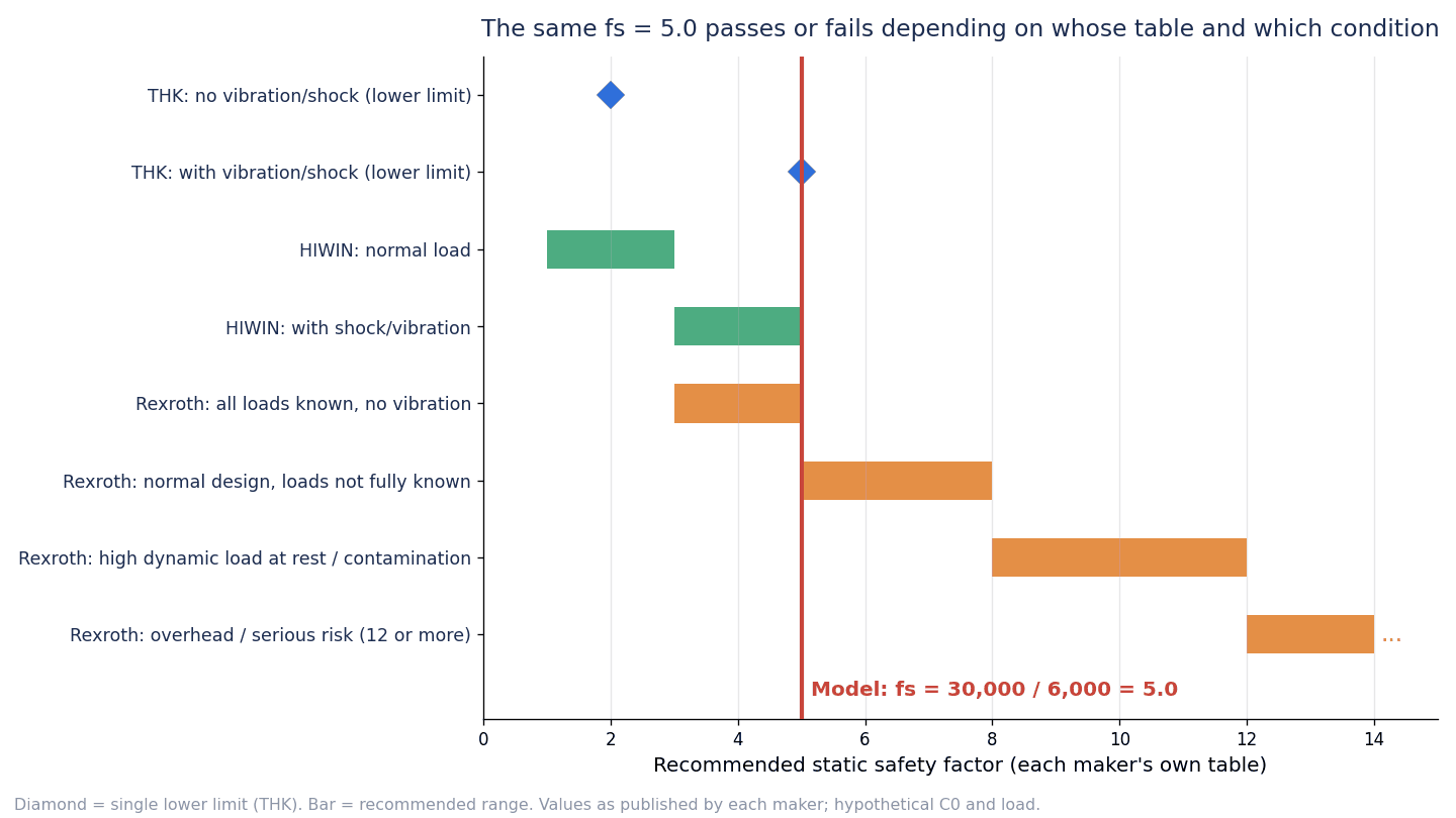
| Manufacturer’s table | Condition applied | Recommended value | Verdict for fs = 5.0 |
|---|---|---|---|
| THK | No vibration or impact | Lower limit 2 | Margin available |
| THK | With vibration or impact | Lower limit 5 | Exactly at the lower limit |
| HIWIN | Normal load | 1.0–3.0 | Meets |
| HIWIN | With impact or vibration | 3.0–5.0 | Upper end of the range |
| Bosch Rexroth | All load data known, vibration-free | 3–5 | Upper end of the range |
| Bosch Rexroth | Normal machine design without full knowledge of load conditions | 5–8 | Lower end of the range |
| Bosch Rexroth | Large dynamic loads while stationary, contamination | 8–12 | Insufficient |
| Bosch Rexroth | Suspended arrangements, etc. | 12 or more | Insufficient |
Even the same 5.0 can be “margin available” or “insufficient,” depending on which manufacturer’s table it is judged against and which operating condition it is matched to. That is why the calculation sheet should state “which manufacturer’s recommended value, for which condition, was used for the judgment.” If the adopted linear guide is made by THK, it is logical to judge with THK’s table; if made by HIWIN, with HIWIN’s table. Then the buyer and the machine builder should agree on the operating conditions, such as how often sudden stops occur, contamination by coolant or chips, and whether the axis passes over workers’ heads.
Linear Guide Life Calculation: Rating Distance, Modification Factors, Life in Hours
Definition of nominal life
THK defines the nominal life L10 as “the total travel distance that 90% of a group of identical LM Guides from the same lot can reach without flaking when each is run under the same conditions.” Bosch Rexroth also defines nominal life as “the calculated life that can be reached with 90% probability.” In other words, the calculated life is not “the distance that every unit will last.”
Basic formulas
The nominal life formulas in HIWIN’s technical information are as follows.
- Ball type: L = (C/P)^3 × 50 km
- Roller type: L = (C/P)^(10/3) × 100 km
The formulas that take the operating environment into account include the hardness factor fh, the temperature factor ft and the load factor fw: for ball types, L = ((fh·ft·C)/(fw·Pc))^3 × 50 km, and for roller types, L = ((fh·ft·C)/(fw·Pc))^(10/3) × 100 km.
NSK’s NH/NS series catalog uses separate formulas for each rating distance: L = 100 × (C100/(fw·F))^3 or L = 50 × (C50/(fw·F))^3 [km]. NSK notes that “the calculation formula differs for linear guides with rollers as rolling elements.”
Modification factors also differ by manufacturer
| Manufacturer | Modification factor | Content (each manufacturer’s definition) |
|---|---|---|
| THK | α = fH·fT·fC/fW | Hardness factor fH (1.0 unless otherwise specified), temperature factor fT (applied above 100°C), contact factor fC (blocks in close contact), load factor fW |
| HIWIN | fh, ft, fw | Hardness factor, temperature factor, load factor. No factor equivalent to THK’s fC in the formula |
| NSK (NH/NS series) | fw | Load factor. Classified by degree of impact and vibration, not by speed range |
THK’s contact factor fC is the factor used when multiple blocks are placed in close contact: 0.81 for 2 blocks in contact, 0.72 for 3, 0.66 for 4, 0.61 for 5, 0.6 for 6 or more, and 1 for normal use.
The load factor tables are as follows. THK’s speed ranges of 0.25/1/2 m/s have the same boundaries as HIWIN’s 15/60/120 m/min.
| Category | THK fW | HIWIN fw | NSK fw (NH/NS series) |
|---|---|---|---|
| Faint vibration/impact (THK: V≤0.25 m/s) / No impact or vibration (HIWIN: V≤15 m/min) | 1–1.2 | 1–1.2 | No external impact or vibration 1.0–1.5 |
Weak (0.25| 1.2–1.5 | 1.2–1.5 | External impact or vibration 1.5–2.0 | |
Medium (1| 1.5–2 | 1.5–2.0 | Severe impact or vibration 2.0–3.0 | |
| Strong (V>2 m/s) / With impact or vibration (V>120 m/min) | 2–3.5 | 2.0–3.5 | (No category) |
Because the NSK column has no speed ranges, it does not correspond one-to-one with the rows beside it. The arrangement of the table is only for readability.
Converting to life in hours
Converting distance life into time makes it easier to compare with the machine’s maintenance plan. HIWIN uses Lh = (L·10^3)/(Ve·60) [hours] (Ve: speed in m/min), and Bosch Rexroth states that, when the stroke length s and the number of stroke repetitions n are constant, life in hours is obtained by dividing L10 by (2·s·n·60). Both divide by “the travel distance per hour.”
Short strokes and reliability
THK states that when the stroke length is 2 times the LM block length or less, the nominal life formula may not apply. Bosch Rexroth also states that when the stroke length is less than 2 times the runner block length, a reduction of the load capacity may be required. For short strokes, such as the pressing mechanisms and alignment axes of inspection equipment, it is important not to feel reassured by the life calculation figures alone (see also fretting below).
When the required reliability differs from 90%, Bosch Rexroth provides a table for converting life with the reliability factor a1.
| Reliability | Life symbol | a1 |
|---|---|---|
| 90% | L10a | 1.00 |
| 95% | L5a | 0.64 |
| 96% | L4a | 0.55 |
| 97% | L3a | 0.47 |
| 98% | L2a | 0.37 |
| 99% | L1a | 0.25 |
These are values published in the Bosch Rexroth catalog. If you want to raise the reliability for an axis whose stoppage would have a large impact, have the calculation sheet state which manufacturer’s conversion was used.
Model calculation: one reading changes life from about 2 times to about half
From here on, the figures are hypothetical, not values for any specific product or model number, placed to show the structure and sensitivity of the calculation. The formula used is HIWIN’s nominal life formula (ball type) L = ((fh·ft·C)/(fw·P))^3 × 50 km, and only for the case of blocks in close contact do we borrow THK’s concept of the contact factor fC. Because the factors differ by manufacturer, an actual calculation should use the formula and factors of the manufacturer you adopt.
The assumptions of the model are as follows.
- Horizontal axis of an inspection machine. Ball type linear guide, 2 rails × 4 blocks
- Load per block P = 2,000 N (hypothetical)
- Catalog basic dynamic load rating C = 20,000 N (hypothetical, assumed to be on a 50 km basis)
- fh = ft = 1.0
- fw = 1.5 for a speed range of 1 m/s or less (the upper side of THK’s and HIWIN’s “1.2 to 1.5 for 0.25 to 1 m/s (15 to 60 m/min)”)
- Stroke 0.8 m, 10 round trips per minute → travel distance 2 × 0.8 × 10 = 16 m/min = 960 m/h
- Operation 16 hours/day × 300 days/year = 4,800 hours/year
- The effect of preload is not included (THK states that a life calculation taking the preload amount into account is required when using medium preload)
- A stroke of 0.8 m is assumed not to fall under the short-stroke condition
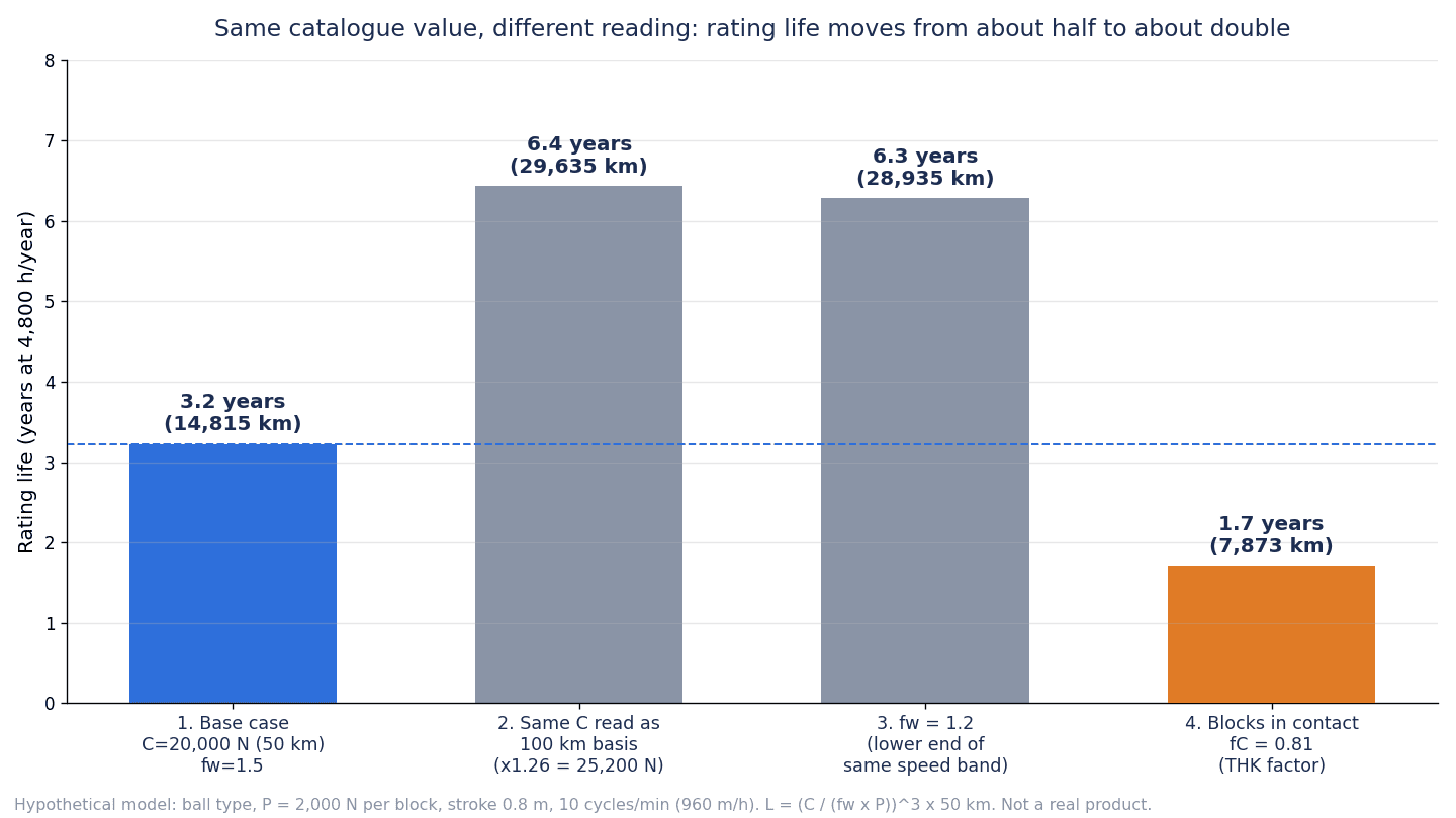
| Case | Condition | Rating life L | Life in hours | Years (4,800 h/year) |
|---|---|---|---|---|
| ① Base | C=20,000 N (50 km basis), fw=1.5 | About 14,815 km | About 15,432 hours | About 3.2 years |
| ② Rating distance mix-up | The catalog’s 20,000 N is actually on a 100 km basis (per Rexroth’s statement, conversion to a 50 km basis is ×1.26 = 25,200 N) | About 29,635 km | About 30,870 hours | About 6.4 years |
| ③ Load factor read at the lower limit | fw=1.2 (lower limit of the same speed range) | About 28,935 km | About 30,141 hours | About 6.3 years |
| ④ Blocks in close contact | THK contact factor fC=0.81 (2 blocks in contact) | About 7,873 km | About 8,201 hours | About 1.7 years |
The calculations are as follows. Life in hours is obtained in every case as L × 1,000/960.
- ① (20,000/(1.5 × 2,000))^3 × 50 = 6.667^3 × 50 ≈ 14,815 km
- ② (25,200/3,000)^3 × 50 = 8.4^3 × 50 ≈ 29,635 km
- ③ (20,000/2,400)^3 × 50 = 8.333^3 × 50 ≈ 28,935 km
- ④ (0.81 × 20,000/3,000)^3 × 50 = 5.4^3 × 50 ≈ 7,873 km
Case ② needs attention to direction. Converting a C on a 100 km basis to a 50 km basis makes C 1.26 times larger and the life about 2 times longer. Put another way, entering a C on a 100 km basis as-is into a 50 km-basis formula underestimates life, and conversely, treating a C on a 50 km basis as if it were on a 100 km basis overestimates it. Comparing 2 companies without aligning the basis creates an apparent difference of about 2 times in life. The 1.26 is stated in Bosch Rexroth’s ball type catalog and is also consistent with (100/50)^(1/3) ≈ 1.26. Because it is a value for ball types, this article does not cover conversion for roller types. For roller types, check the documents of the manufacturer you adopt.
Case ③ shows that just choosing fw at the upper limit of 1.5 or the lower limit of 1.2 within the same speed range moves the life from about 3.2 years to about 6.3 years. The choice of load factor involves the designer’s judgment, so having the calculation sheet state “why that value was chosen” makes it possible to verify it later.
Case ④ is an example in which placing 2 blocks in close contact means, under THK’s approach, multiplying C by 0.81, which lowers life to about 1.7 years. The block arrangement can change later because of the table length or the available mounting space. An agreement is needed that the life calculation is redone whenever the arrangement changes.
In summary, even with the same catalog value, one reading of the rating distance, the load factor or the arrangement moves the life to about 2 times (②, ③) or about half (④) of the roughly 3.2 years in ①. That is why the calculation sheet should state the manufacturer definitions, factors and rating distance used.
Linear Guide Preload and Rigidity: Categories and Colliding Symbols
What preload changes
Preload is a mechanism that applies an internal load in advance between the block, the rolling elements and the raceway to eliminate clearance and increase rigidity. HIWIN writes that “increasing the preload increases rigidity but reduces nominal life.” THK shows that the effect of preload lasts up to an external load of at most about 2.8 times the preload amount, beyond which the preload is released, and that the displacement with preload is about half of that without preload. Bosch Rexroth states that, to prevent a reduction in life, the preload should not exceed 1/3 of the bearing load F, and that C2 or higher should be selected when there is vibration (C2 here is Rexroth’s preload class symbol).
Each manufacturer’s preload categories
In this article, preload is written in words, “no preload / light preload / medium preload / heavy preload,” with the manufacturer’s symbols in parentheses.
| Manufacturer | Category (manufacturer’s symbol) | Main applications and description (as stated by each manufacturer) |
|---|---|---|
| HIWIN (HG series) | Light preload (Z0) = 0–0.02C | Constant load direction, small impact, low accuracy requirements. Conveying equipment, automatic packaging machines, XY axes of general industrial machinery, welding machines |
| HIWIN (HG series) | Medium preload (ZA) = 0.05C–0.07C | High accuracy requirements. Machining centers, Z axes of general industrial machinery, electrical discharge machines, NC lathes, precision XY tables, measuring machines |
| HIWIN (HG series) | Heavy preload (ZB) = 0.10C–0.12C | High rigidity requirements, with vibration or impact. Machining centers, grinding machines, Z axes of machine tools, heavy cutting machines |
| THK | Normal clearance | Constant load direction with small impact and vibration, used with 2 rails in parallel, sliding resistance to be kept as low as possible (automatic packaging machines, XY axes of general industrial machinery, welding machines, etc.) |
| THK | Light preload (clearance C1) | Overhang loads or moment loads, used with a single rail, light loads with high accuracy (industrial robots, vertical axes of general industrial machinery, measuring machines, precision XY tables, etc.) |
| THK | Medium preload (clearance C0) | High rigidity needed, with vibration and impact (machining centers, NC lathes, grinding machines, vertical axes of machine tools, etc.) |
| Bosch Rexroth | No preload (C0), moderate preload (C1), average preload (C2), high preload (C3) | Preload no more than 1/3 of the bearing load F. C2 or higher if there is vibration |
| NSK (NH/NS series, assembled products) | Fine clearance (Z0), light preload (Z1), medium preload (Z3) | Example preload amounts: for NH25 AL/AN/EM, light preload 196 N, medium preload 1,270 N |
| NSK (NH/NS series, interchangeable type) | Fine clearance (ZT), light preload (ZZ), medium preload (ZH) | Example clearances (µm, negative means preload): for NS15, ZT −4 to 15, ZZ −4 to 0, ZH −7 to −3 |
HIWIN’s preload amounts are expressed as a proportion of the basic dynamic load rating C, and this is HIWIN’s definition. HIWIN offers light and medium preload (Z0 and ZA) for the interchangeable type and up to heavy preload (ZB) for the non-interchangeable type, and for sizes HG20 and below recommends medium preload (ZA) or lower so that excessive preload does not affect life. NSK’s fine clearance (Z0) is 0 to 3 µm (zero preload), but becomes 0 to 15 µm when combined with the PN grade.
THK states that all models except the 3 models HR, GSR and GSR-R have their clearance adjusted before shipment and need no additional preload adjustment.
Watch for colliding symbols
Preload symbols collide in meaning across manufacturers.
- THK’s “C0” is the clearance symbol for medium preload
- Bosch Rexroth’s “C0” is the no preload category
- And the symbol for the basic static load rating is also “C0”
- HIWIN’s “Z0” is light preload, while NSK’s “Z0” is fine clearance
If a specification says only “preload C0,” it can be read as medium preload or as no preload depending on the recipient, and it may even be confused with the static load rating. In specifications, make words and quantities (or ranges) the main description, such as “medium preload (THK clearance symbol C0),” and limit manufacturer symbols to being written alongside.
Higher preload means smaller permissible mounting-surface error
The choice of preload affects not only rigidity and life but also the accuracy of the mounting surfaces. In HIWIN’s table of permissible values for the mounting surfaces of the HG series, the larger the preload for the same size, the smaller the permissible parallelism and height errors of the reference surfaces (see the table in the next chapter for details). Bosch Rexroth also says to pay attention to the permissible parallelism offset of the rails when selecting a preload class, and when assembling with normal accuracy (accuracy class N), recommends no preload (C0) or moderate preload (C1) to avoid internal stresses caused by tolerances.
As examples of rigidity values, HIWIN’s HG series gives 196, 365 and 483 N/µm for light, medium and heavy preload on the HG15C, 292/539/705 N/µm on the HG25C, and 395/642/865 N/µm on the HG35C (values per model and direction, not to be compared side by side with other companies’ values). Rigidity k is P/δ and expresses how small the displacement is per unit load.
Before deciding “we want rigidity, so heavy preload,” check whether the mounting surfaces can be machined and installed to that accuracy, and whether the effect of preload was included in the life calculation.
Linear Guide Accuracy Classes and Mounting Surfaces
Each manufacturer’s names for accuracy classes
| Manufacturer | Accuracy classes (from lowest) |
|---|---|
| THK | Normal grade (Normal), High grade (H), Precision grade (P), Super precision grade (SP), Ultra precision grade (UP) |
| HIWIN (HG series) | C (Normal), H (High), P (Precision), SP (Super Precision), UP (Ultra Precision) |
| NSK (NH/NS series, assembled products) | PN (Normal), P6 (Precision), P5 (High precision), P4 (Super precision), P3 (Ultra precision) |
| NSK (NH/NS series, interchangeable type) | PC (Normal), PH (High precision) |
| Bosch Rexroth | N, H, P, SP, UP (XP is listed for the high-precision runner block BSHP) |
| IKO (LRXD8…SL) | High grade H, Precision grade P, Super precision grade SP, Ultra precision grade UP |
Even when the symbols are the same, such as H, P, SP and UP, the permissible values differ by manufacturer, model and rail length. You cannot generalize that “P grade means so many µm.” NSK’s P3 to PN are also categories for the NH/NS series.
Definition and measurement conditions of running parallelism
THK specifies accuracy in terms of “running parallelism,” “dimensional tolerance of height and width” and “mutual difference in height and width when multiple units are used on the same plane.” Running parallelism is “the permissible parallelism between the block and the rail reference surface when the LM rail is bolted to a reference surface and the LM block is run over the full length of the rail.” The measured value is taken at the center point or as the average of the center portion of the block.
In addition, THK states that when multiple rails are used in parallel on the same plane, the mutual difference in width and the dimensional tolerance apply only to the master rail, and that this must be specified if you want them applied to the subsidiary rails as well. The master rail is marked with “KB” at the end of the serial number (Normal grade is not covered).
When writing “running parallelism XX µm” in the RFP, also writing these measurement conditions (bolted to a reference surface, run over the full length, value at the center portion) makes disputes over “how it was measured” less likely at acceptance.
Example running parallelism for the HIWIN HG series
| Rail length | C | H | P | SP | UP |
|---|---|---|---|---|---|
| Up to 100 mm | 12 | 7 | 3 | 2 | 2 |
| 500–700 mm | 20 | 13 | 7 | 4 | 2 |
| 1,100–1,500 mm | 26 | 18 | 11 | 7 | 4 |
| 3,600–4,000 mm | 37 | 28 | 21 | 15 | 7 |
The unit is µm, excerpted from HIWIN’s technical information for the HG series. Even within the same class, the longer the rail, the larger the permissible value. When deciding the accuracy class for a long-stroke axis, read the table with the rail length included as a condition. IKO explains that, for the LRXD8…SL, running parallelism can be 1 µm or less depending on conditions (the manufacturer’s explanation).
Parallelism and height of mounting surfaces (example: HIWIN HG series)
A linear guide’s accuracy is achieved only when the accuracy of the mounting surfaces is also in place. The permissible values for the mounting surfaces of the HIWIN HG series are as follows (unit: µm).
| Size | Parallelism of reference surfaces P (light preload Z0 / medium preload ZA / heavy preload ZB) | Height tolerance of reference surfaces S1 (light preload Z0 / medium preload ZA / heavy preload ZB) |
|---|---|---|
| HG15 | 25/18/13 | 130/85/35 |
| HG20 | 25/20/18 | (not excerpted) |
| HG25 | 30/22/20 | 130/85/70 |
| HG30 | 40/30/27 | (not excerpted) |
| HG35 | 50/35/30 | 210/150/120 |
| HG45 | 60/40/35 | (not excerpted) |
| HG55 | 70/50/45 | (not excerpted) |
| HG65 | 80/60/55 | 350/250/200 |
“(not excerpted)” marks sizes for which this article has not excerpted the height values. For every size, the larger the preload, the smaller the permissible value. HIWIN states that its circular-arc contact design can absorb mounting-surface errors to some extent, and that high accuracy and rigidity can be obtained if the accuracy requirements for the mounting surfaces are observed; it also offers a normal-clearance preload with high tolerance for mounting-surface errors. NSK likewise explains that, for the NH/NS series, a contact structure similar to the DF arrangement of rolling bearings lowers moment rigidity and increases the ability to absorb mounting errors (the manufacturer’s explanation).
When mounting on aluminum bases or jigs
THK states that, when mounting on a base with low rigidity such as an aluminum base, the straightness of the rail must be specified in advance because bending of the rail affects machine accuracy. Aluminum frames are widely used in inspection equipment and lightweight conveying units. The machining tolerances and measurement methods for the base are, as covered in “Jig Design & Manufacturing in Thailand: RFQ to Acceptance,” items to be written on the drawing as numbers and measurement methods and confirmed at acceptance.
Selecting by Environment: Lubrication, Seals, Rust Prevention, Temperature
Lubrication
THK gives 3 roles for lubrication: (1) reducing friction to prevent seizure and wear, (2) forming an oil film on the raceway to reduce stress and extend rolling fatigue life, and (3) preventing rust. Even with seals, the internal lubricant gradually leaks out, so lubrication at intervals suited to the operating conditions is necessary. THK also notes that with mounting orientations other than horizontal, the lubricant may not reach the raceways, and asks that the mounting orientation and the positions of grease nipples and piping fittings be communicated to THK.
HIWIN recommends lubricating with lithium-soap-based grease before installation and regreasing every 100 km after installation (the HG series page says “check the grease every 100 km or every 3 to 6 months”). Grease is generally used at speeds of 60 m/min or less, and high-viscosity oil is used at higher speeds; the recommended oil viscosity is about 30 to 150 cSt, and the recommended oil feed rate is about 0.3 cm³/hr. The lubrication interval is obtained from T = (100 × 1000)/(Ve × 60) [hours]. “Every 100 km” is HIWIN’s recommendation; THK does not give a fixed distance. Build the maintenance plan on the recommendations of the adopted manufacturer.
For wall-mounted or ceiling-mounted axes and axes deep behind covers, whether the lubrication port can be reached determines whether lubrication actually takes place. Decide the position of the lubrication ports, and whether to use centralized lubrication or manual greasing, at the design stage.
Seals and scrapers
Entry of foreign matter causes abnormal wear and shortened life (THK). Every company offers a range of seal types.
- THK: end seals, side seals, inner seals, the laminated contact scraper LaCS for harsh environments, dedicated bellows, and caps for rail mounting holes (to prevent chip entry)
- HIWIN (HG series): the standard is end seals + bottom seals. ZZ (end seals + bottom seals + scrapers), KK (double seals + bottom seals + scrapers), DD (double seals + bottom seals), and high dust protection KH, SH, ZH, etc. (available for C/H of HG20 to 35 and 45C)
- NSK (NH/NS series): end seals on both ends and bottom seals as standard
- Bosch Rexroth: standard seal SS, low-friction seal LS (limited wiping action), double-lip seal DS (for applications with many chips, wood dust or cutting fluid; its wiping action is excellent but friction is high and the relubrication interval becomes shorter)
Stronger sealing increases sliding resistance. The maximum resistance per end seal for the HIWIN HG series is 2.35 N for HG15, 3.14 N for HG25, 4.91 N for HG35 and 5.79 N for HG65, and the seal friction (maximum value) per ball slide for the NSK NH series is 8 N for size 15, 10 N for 25, 12 N for 35, 17 N for 45 and 29 N for 65. Bosch Rexroth states in text rather than numbers that DS has high friction. Decide the selection of drive-side motors and ball screws, and the running resistance criteria at acceptance, after fixing the seal specification. HIWIN expresses friction force as F = µ·W + S (S is frictional resistance such as seal resistance).
Rust prevention and stainless steel
“Stainless steel” actually covers several different specifications.
- THK: martensitic stainless steel is available for some models (SHS, SSR, SHW, SRS, HSR, SR, HRW, RSX, RSR, HR). HSR-M2 is a high-corrosion-resistance type made of austenitic stainless steel. Surface treatments include THK-AP (AP-HC, AP-C, AP-CF).
- Bosch Rexroth: Resist NR (runner block body of corrosion-resistant steel per DIN EN 10088), Resist NR II (all steel parts of corrosion-resistant steel), Resist CR (steel with corrosion-resistant coating, hard chrome plating)
- NSK (NH/NS series): the maximum length of stainless steel rails is shorter than that of carbon steel rails. For the NH series, special high-carbon steel rails reach a maximum of 2,980 to 4,000 mm depending on size, while stainless steel rails are 1,800 or 3,500 mm for the 4 sizes with values in the table.
Changing the material may change the load ratings and the maximum rail length. Check the load ratings of stainless products individually in the dimension tables, and redo the life calculation and static safety factor with those values.
Operating temperature
| Manufacturer | Guideline operating temperature (as stated by each manufacturer) |
|---|---|
| THK | 80°C or less for LM Guides that are not high-temperature specifications (consult THK above 80°C). Temperature factor fT applied above 100°C |
| HIWIN | Below 100°C recommended because accessory parts contain resin. Permissible load decreases above 100°C |
| Bosch Rexroth | 0 to 80°C in general data, up to 100°C for short periods. Lower limit −10°C for runner blocks without ball chains |
Points to watch at plants in Thailand
At plants in Thailand, hot and humid seasons, buildings without air conditioning, machining lines using large amounts of coolant and dusty processes are not unusual. This article does not generalize numerical criteria here, but the approach is as follows.
- In environments prone to rust, decide the material (type of stainless steel), surface treatment, seals and lubricant as a set. NSK’s damage cases include one in which chlorine-based cutting fluid got past the protective cover and rusted the raceways and balls
- The storage period from shipment of the machine to start-up and the environment during transport can also cause corrosion (NSK lists improper storage as a cause of corrosion)
- In processes that produce chips, consider caps for rail mounting holes, scrapers, bellows and so on, and also allow for the increase in sliding resistance due to differences in seal specifications
- For axes near heat sources, check that they stay within the adopted manufacturer’s operating temperature range
5 Causes of Premature Damage and Countermeasures
When correctly selected, installed and maintained, a linear guide reaches the end of its life through flaking due to rolling fatigue (a phenomenon in which the surface peels off in scales). Life is “the total travel distance until flaking first occurs on any raceway or rolling element” (THK and HIWIN state this to the same effect). However, NSK states that premature flaking and abnormal damage can occur, and that the causes are careless handling, excessive mounting error (misalignment), insufficient lubrication and contamination, which may also be combined. NSK also writes that investigating the product, handling, installation, maintenance history and progression helps prevent recurrence.
| Damage | Presumed causes (as stated by NSK) | Countermeasures (as stated by NSK) | Case (NSK) |
|---|---|---|---|
| Flaking | End of life, assembly defects (misalignment), poor flatness of mounting surfaces, insufficient lubrication or unsuitable lubricant, progression from indentations or corrosion pits, entry of foreign matter or water | Review size, improve assembly accuracy and mounting-surface accuracy, review lubrication method and lubricant, avoid impact loads, review protective covers and strengthen seals | Flaking on the opposing raceways of the rail due to excessive rolling moment from assembly misalignment |
| Wear | Insufficient lubrication, entry of foreign matter, improper mounting (misalignment) | Review lubrication, measures against foreign matter and mounting | Wear of slider raceways due to insufficient lubrication from clogged oil supply piping |
| Fretting | Oscillation with very small amplitude completely dries the lubricant at the contact areas | Use anti-fretting grease, periodically run a long stroke to spread the lubricant (e.g., once every 5,000 cycles) | Reddish-brown or black wear debris appears (fretting corrosion) |
| Indentations (brinelling) | High-energy impact or improper handling during mounting or transport, entry of hard metal particles | Proper mounting and handling, strengthened seals, filtration of lubricating oil | Indentations on raceways because a table fixed to the blocks was lifted, suspending the heavy machine base with the rails fixed to it |
| Corrosion | Entry of water or corrosive substances, unsuitable lubricant, improper storage | Strengthen seals, change to materials or surface treatments with higher acid resistance, review the lubrication system, review storage conditions | Chlorine-based cutting fluid got past the protective cover and rusted the raceways and balls |
THK also writes that foreign matter causes abnormal wear and shortened life, and that without lubrication, wear of the rolling elements and raceways accelerates and life becomes shorter. HIWIN states that insufficient lubrication greatly shortens life through increased rolling friction.
This table shows the points where the buyer can take action.
- Mounting error: write the permissible parallelism and height of the mounting surfaces in the specification, and have the installation procedure and tightening torque recorded
- Lubrication: decide the lubrication method, interval and lubrication port positions at the design stage, and include clogging of piping in the inspection items
- Contamination and corrosion: select seals, covers, materials and surface treatments suited to the environment
- Handling: decide the transport and lifting methods, and do not lift a heavy base through the blocks
- Short strokes and oscillation: do not feel reassured by the life calculation figures alone; consider anti-fretting grease and periodic long-stroke operation
When linear guides in existing machines are wearing out early, use these 5 angles to investigate in turn whether the cause is likely to lie in mounting, lubrication, environment or handling. For how to approach parts replacement in older equipment, see also “Legacy Equipment Replacement 2026 — Four Deadlines Before the Parts Vanish.”
Items to Write in a Linear Guide RFP (Request for Proposal)
Here we summarize the content so far as RFP items. They are in a form usable both when ordering a complete machine from a machine builder or system integrator and when purchasing linear guides as components.
| # | Item | What to write | Reason |
|---|---|---|---|
| 1 | Operating conditions | Stroke, speed, acceleration/deceleration, mounting orientation, operating hours, environment (chips, coolant, dust, humidity, temperature) | Basis for load factor, seals and lubrication |
| 2 | Load conditions and equivalent load | Loads by direction, peak loads, moments, the manufacturer’s formula and factors used for conversion | Factors differ by model |
| 3 | C value and rating distance | Include a “rating distance of the C value (50 km/100 km)” column in the comparison sheet | Different bases make life appear to differ by about 2 times |
| 4 | Life calculation sheet | Manufacturer definitions used, values of modification factors and reasons for choosing them, required life, conversion to life in hours, whether the effect of preload is included | So that it can be verified later |
| 5 | Static safety factor | Calculated value, and the recommended value of the manufacturer and condition used for the judgment | The same value can pass or fail depending on the table |
| 6 | Preload | Words (“no preload / light preload / medium preload / heavy preload”) and quantity (or range). Manufacturer symbols written alongside | Symbols collide between manufacturers |
| 7 | Accuracy class and measurement conditions | Class, running parallelism value and measurement conditions, scope of application to master/subsidiary rails | The numbers change with the measurement method |
| 8 | Permissible values for mounting surfaces | Parallelism and height of reference surfaces (from the adopted manufacturer’s table), base material and straightness | The larger the preload, the smaller the permissible values |
| 9 | Seal specification | Seal type, scrapers, bellows, mounting hole caps | Sliding resistance and dust protection change |
| 10 | Lubrication | Type of lubricant, lubrication method and interval, lubrication port positions (communicate the mounting orientation) | Depending on orientation, lubricant may not reach the raceways |
| 11 | Rust prevention specification | Material (type of stainless steel), surface treatment, rust prevention at shipment and storage conditions | Even stainless steel comes in several specifications |
| 12 | Installation procedure and torque | Cleaning of mounting surfaces, pressing against reference surfaces, tightening torque, method of aligning the subsidiary rail in parallel | Mounting error is a main cause of premature damage |
| 13 | Transport and lifting | Lifting points, no lifting through the blocks, securing during transport | There are cases of indentations |
| 14 | Spare parts and maintenance documents | Spare blocks and seals, lubrication inspection sheets | To keep maintenance running on site |
| 15 | Confirmation of supply in Thailand | Supply route, stock and rail cutting service in Thailand for the adopted manufacturer and model | Affects lead time at replacement |
If all you have received from the machine builder is the single line “Linear guide, Company XX, Model XX,” simply getting the 4 items 3, 4, 5 and 6 in writing first will give you a common basis for comparison. Acceptance and the division of responsibility for the whole drive system including servo motors are covered in “Servo Control Procurement and FAT/SAT Guide for Thailand Plants in 2026,” and buying short-stroke axes as complete actuators is covered in “Electric Cylinder Selection for Thai Factories.”
What to Check at FAT/SAT
At FAT (factory acceptance test, before shipment) and SAT (site acceptance test, after installation on site), you verify on the actual equipment that the items written in the RFP have been met. For linear guides, the check items assembled from what is written in the technical documents are as follows.
| Test item | Method | Criterion | Record |
|---|---|---|---|
| Matching of model, preload category and accuracy class | Match the model, preload category and accuracy class of the actual items against the drawings and shipping documents | Matches the RFP | Matching sheet |
| Master/subsidiary rail combination | For HIWIN non-interchangeable types, check the pairing of the master rail (“MA” marking, odd number) and the subsidiary rail (even number) (e.g., 001 and 002); for THK, check “KB” at the end of the master rail serial number (Normal grade not covered) | Combination as specified | Photos |
| Butt-jointed rails | Whether the arrows and numbers are followed, and, when 2 rails are used in parallel, whether the joint positions are staggered (HIWIN’s procedure) | As per procedure | Photos |
| Tightening torque | Specified torque with a torque wrench (e.g., HIWIN HG25, M6: steel 1,373 N·cm, cast iron 921 N·cm, aluminum 686 N·cm) | The adopted manufacturer’s specified value | Torque record |
| Running parallelism | Measurement conditions agreed in the RFP (bolted to a reference surface, run over the full length, value at the center portion) | Agreed permissible value | Measurement data |
| Sliding resistance | Compare under the same specification conditions (seals, lubricant, preload) | Criterion agreed with the manufacturer | Measurement data |
| Abnormal noise and catching | Run the full stroke at low speed and normal operating speed | No abnormal noise or catching | Test record |
| Lubrication | Whether lubricant reaches from the lubrication port, whether lubrication is possible in the mounting orientation, whether piping is clogged | Lubrication possible | Inspection record |
| Cleaning of rust preventive oil | Whether the rust preventive oil applied at shipment was cleaned off before running (HIWIN’s procedure) | Cleaned | Work record |
| Condition after transport and installation | At SAT, check running, abnormal noise and lubrication again | No difference from FAT | SAT record |
According to HIWIN’s procedure, there are 4 ways to align the subsidiary rail in parallel: using a straightedge and dial gauge, using the table, following the main side, and using a dedicated jig. Have the method used recorded.
Regarding preload, THK states that clearance is adjusted before shipment (the 3 models HR, GSR and GSR-R are not covered), and NSK shows the clearance and preload ranges in µm for the interchangeable type and the assembled products respectively. At acceptance, the basic approach is to match documents and actual items to confirm that products of the specified preload category have been installed.
Sliding resistance changes with seal specification, preload, lubricant and load. Rather than setting a uniform absolute criterion, it is realistic to agree a reference value with the manufacturer as a comparison under the same specification conditions.
Points to Check When Procuring in Thailand
Local bases (to the extent confirmed in official documents)
The Thai bases that could be confirmed in official documents for this article are those of THK and NSK.
- THK: THK’s service network document (CATALOG No.55-14) lists THK LM SYSTEM (THAILAND) CO., LTD. (Samut Prakan Province, Bangna Tower), with support in Thai, Japanese and English, and LM Guides and ball screws listed as stock items. It also lists I.N.B. Enterprise, KKC Bearing Service (including a support desk in Rayong) and YAMAZEN (THAILAND) (with offices in Sriracha, Korat, Lamphun and elsewhere) as distributors in Thailand. The document contains indications that can be read as stock and cutting service, but it does not state specific stock quantities or lead times.
- NSK: NSK Bearings (Thailand) Co., Ltd. is a joint venture between Siam Motors and NSK, has been operating in Bangkok since 1987, and is described as supplying precision bearings, ball screws and linear guides to the automotive and industrial markets. Thailand is also home to the NSK Asia Pacific Technology Center, which provides technical support for the Asia-Pacific region.
This article has not confirmed the bases or stock arrangements in Thailand of other manufacturers. For each candidate manufacturer, check directly the stock at the model-number level, lead times, rail cutting service and the contact point for technical consultation. In particular, when a machine builder designs on the premise of overseas standard products, whether replacement parts can be procured in Thailand directly affects downtime after start of operation.
BOI efficiency measures (within the scope of the 2025 guide)
The Thailand Board of Investment (BOI) Investment Promotion Guide 2025 includes, as “measures for upgrading to smart and sustainable industry,” a measure for improving efficiency through machinery upgrading or replacement and automation for existing businesses. According to the guide, it covers existing operating businesses regardless of whether they hold BOI promotion; the investment must be 1 million baht or more excluding land costs and working capital; and the incentives are import duty exemption on machinery and a 3-year corporate income tax exemption (capped at 50% of the improvement investment, excluding land costs and working capital). When automation or robots are introduced and 30% or more of their value is linked to or supports the automation industry in Thailand, the cap becomes 100% of the investment. There is also a measure for projects introducing automation and robot systems, which requires submission of an investment plan for automation and robots at the time of application. The guide also lists industries that are not eligible.
There are 2 points to note. First, the measures cover investment in machines and systems; the guide does not say that purchasing standalone components such as linear guides is eligible. Second, this is what the 2025 guide states, and the current acceptance status and any amendments need to be confirmed directly with the BOI. The content of this article is not tax advice.
Check at trade shows
METALEX 2026, scheduled to be held at BITEC in Bangkok from November 18 to 21, is a trade show for machinery, metalworking and manufacturing technology. This article has not confirmed which manufacturers or products will be exhibited, but if a candidate manufacturer is exhibiting, it is a good opportunity to ask on the spot about the rating distance of C values, the recommended values for the static safety factor, the definitions of preload and accuracy classes, and stock in Thailand. For an overall picture of ordering the design and build of automated machines, “Custom Automation Machine Design and Build | Cost Breakdown” is also a useful reference.
Frequently Asked Questions
How do you calculate linear guide life?
Calculate with the formula of the manufacturer you adopt. For HIWIN ball types, it is L = ((fh·ft·C)/(fw·P))^3 × 50 km; for roller types, the exponent is 10/3 and the rating distance is 100 km. THK uses the modification factor α = fH·fT·fC/fW, and the contact factor fC is included when blocks are placed in close contact. Distance life is converted to life in hours by dividing by the travel distance per hour. Always check the rating distance of C (50 km or 100 km), and also note that for short strokes of 2 times the block length or less, the formula may not apply.
Which linear guide preload should I choose?
In the companies’ documents, normal clearance or light preload is given as an example for conveying equipment and similar applications with a constant load direction and small impact; light to medium preload for applications with high accuracy or moment loads; and medium or heavy preload for machine tools and similar applications that need high rigidity and involve vibration and impact. However, raising the preload increases rigidity but reduces life, and the permissible mounting-surface error becomes smaller (HIWIN). In specifications, write it in words and quantities such as “light preload” or “medium preload” rather than symbols, and limit manufacturer symbols to being written alongside.
What are the differences between linear guide accuracy classes?
THK, HIWIN and Bosch Rexroth use similar symbols such as H, P, SP and UP, while NSK’s NH/NS series uses P3 to PN and PH and PC. Even with the same symbol, the permissible values differ by manufacturer, model and rail length. For example, the running parallelism of the HIWIN HG series in P grade is 3 µm for rail lengths up to 100 mm and 21 µm for 3,600 to 4,000 mm. Specify running parallelism together with its measurement conditions (bolted to a reference surface, run over the full length, value at the center portion).
What static safety factor is needed?
Judge with the recommended values of the manufacturer you adopt. Even under conditions without vibration or impact, the systems differ: THK gives a guideline lower limit of 2, HIWIN 1.0 to 3.0 and Bosch Rexroth 3 to 5 (when all load data are known and vibration-free operation is ensured), and for vibration and impact, contamination or suspended arrangements, Rexroth gives 8 to 12 or 12 or more. Do not use a single number as an industry standard; have the calculation sheet state “which manufacturer’s recommended value, for which condition, was used for the judgment.”
What is the lubrication interval for linear guides?
HIWIN recommends regreasing every 100 km after installation, and its HG series page says “check the grease every 100 km or every 3 to 6 months.” THK does not give a fixed distance and states that lubrication at intervals suited to the operating conditions is necessary. Depending on the mounting orientation, lubricant may not reach the raceways, so decide the position of the lubrication ports at the same time.
Can it be replaced with another manufacturer’s product?
Even if the mounting dimensions are similar, the rating distance of the load ratings, the direction-specific ratings, the definitions of preload and accuracy class, the permissible values for mounting surfaces and the sliding resistance of seals differ by manufacturer, so when replacing, redo the life calculation and static safety factor with the definitions of the replacement manufacturer. There are products that claim compliance with ISO 12090-1/-2, such as THK’s GK Series, but according to THK, interchangeability applies within the range of series, accuracy class (up to Precision grade) and preload category. Treat compliance with standard dimensions and equivalence in performance as separate matters to be checked.
Summary
What to check first in linear guide selection is not the size of the catalog numbers but “which manufacturer’s definitions the calculation used.” For the basic dynamic load rating C, THK and HIWIN ball types are on a 50 km basis, Bosch Rexroth’s ball type catalog is on a 100 km basis, and NSK’s NH/NS series lists both. The recommended values for the static safety factor also differ, with THK 2, HIWIN 1.0 to 3.0 and Bosch Rexroth 3 to 5 under vibration-free conditions, and the preload symbol “C0” means medium preload at THK but no preload at Rexroth.
In the model calculation (hypothetical), against the base case of about 3.2 years in ①, a rating distance mix-up gave about 6.4 years, reading the load factor at the lower limit gave about 6.3 years, and placing blocks in close contact gave about 1.7 years: one reading moved the life from about 2 times to about half. A static safety factor of 5.0 can also be “margin available” or “insufficient,” depending on which manufacturer’s table, for which condition, it is judged against.
That is why the RFP should include 3 things: (1) have the calculation sheet state the manufacturer definitions, factors and rating distance used; (2) specify preload and accuracy in words and quantities and decide them together with the accuracy of the mounting surfaces; and (3) eliminate the main causes of premature damage, namely mounting error, insufficient lubrication, contamination and handling, through FAT/SAT and the maintenance plan. Decide by going back and forth through the 7 selection steps (operating conditions, loads, static safety factor, life, preload, accuracy and mounting surfaces, environment), and verify the actual equipment at acceptance. Proceeding in this order turns the single line “Company XX, Model XX” on the drawing into a specification that can be verified.
TOMAS TECH supports the design of automated machines and inspection equipment and the modification and upgrading of equipment at Japanese plants in Thailand. You can consult us even at stages before the product or supplier has been decided, such as isolating the cause of early linear guide wear in existing machines or drafting RFP specifications. Please contact us through this form.
References
- ISO: ISO 14728-1:2017 Rolling bearings — Linear motion rolling bearings — Part 1
- ISO: ISO 14728-2:2017 Rolling bearings — Linear motion rolling bearings — Part 2
- Japan Bearing Industry Association: Overview of the publication of ISO 14728-1 and -2:2017 (Japanese)
- Japan Bearing Industry Association: List of ISO standards related to rolling bearings, as of June 2026 (Japanese)
- Japanese Standards Association: JIS B 1192-5:2018 preview (Japanese)
- THK: Selection Criteria | LM Guide
- THK: Equivalent Load | Selection Criteria | LM Guide
- THK: Static Safety Factor | Selection Criteria | LM Guide
- THK: Nominal Life | Selection Criteria | LM Guide
- THK: Prediction the Rigidity | Selection Criteria | LM Guide
- THK: Determining the Accuracy | Selection Criteria | LM Guide
- THK: Selection According to the Environment | Selection Criteria | LM Guide
- HIWIN: Linear Guideway Technical Information
- NSK: Linear Guides NH/NS Models (CAT. No. E3332d)
- Bosch Rexroth: Ball rail systems (R999000485/2023-07)
- Bosch Rexroth: Ball Rail Systems overview (R999000485, 2014-12)
- NSK Europe: Linear Guides (Troubleshooting)
- NSK Europe: Flaking (Linear Guides)
- NSK Europe: Wear (Linear Guides)
- NSK Europe: Fretting (Linear Guides)
- NSK Europe: Indentations (Linear Guides)
- NSK Europe: Corrosion (Linear Guides)
- THK GmbH: Interchangeability guaranteed – THK LM Guide GK Series compliant with ISO 12090-1/-2 (July 23, 2026)
- Nippon Thompson: News Release TSA4-26011, smallest size of the Linear Roller Way Super X (October 1, 2026, Japanese)
- Nippon Thompson: News Release TSA7-26010, Linear Motor Table NT100V25 (October 1, 2026, Japanese)
- IKO Nippon Thompson: Latest news (Japanese)
- JIMTOF2026 Secretariat: Press release on holding JIMTOF2026 (September 28, 2026, Japanese)
- Thailand Convention & Exhibition Bureau: METALEX 2026
- Thailand Board of Investment: Investment Promotion Guide 2025
- THK: Global Service Network (CATALOG No.55-14)
- NSK: Thailand


