


When sourcing jig design and manufacturing in Thailand, a drawing and a price are not enough. A supplier may deliver well-machined metal while leaving the buyer without a repeatable, measurable interface to the process. The purchase specification should connect the product datum scheme, locating and clamping concept, error budget, measurement and acceptance plan, wear limits, and controlled release data. This guide follows that evidence chain from the RFQ through FAT, SAT and preventive maintenance for production, inspection and welding fixtures.
Jig design and manufacturing should buy repeatability, not metal
A fixture earns its value when different operators, lots and operating conditions can locate, hold, process or inspect the product against the intended requirements. The procurement question is therefore not only “Can you fabricate this shape?” It is “What establishes the reference, how is the part restrained, what result is acceptable, and how can both parties prove it?”
Acceptance based only on the completed assembly creates three gaps. The buyer cannot see whether physical locators represent the datum system in the product specification. Fixture error, part variation, clamping deformation, temperature and measurement uncertainty may be mixed into one pass/fail result. Finally, there may be no controlled information with which to restore performance after wear or an engineering change.
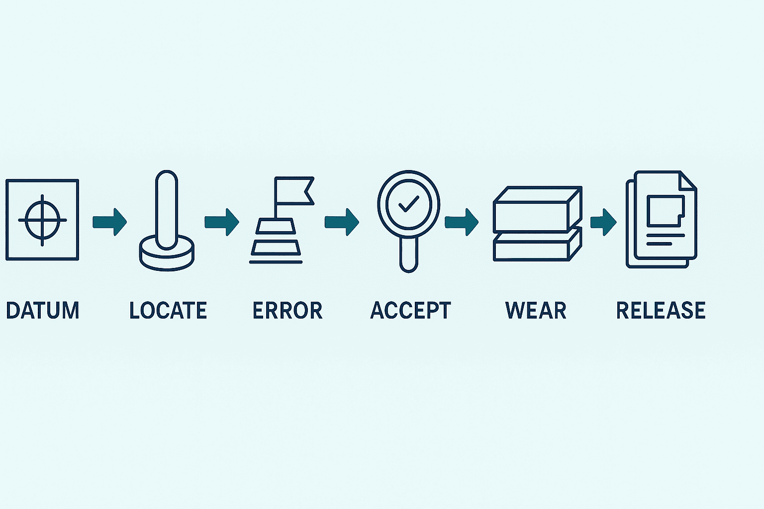
Treat the fixture as six linked records:
- Product datum scheme: the surfaces, holes, axes or centre planes that establish the reference.
- Locating and clamping concept: the constrained degrees of freedom and the reaction path.
- Error budget: the allocation of influential errors and the remaining design margin.
- MSA and acceptance plan: the parts, instruments, environment and decision rule that prove acceptance.
- Wear and maintenance limits: replaceable items, inspections, new-state limits and service limits.
- Change control and release data: drawings, native CAD, BOM, I/O, software and revision history.
These should cross-reference one another. If a product datum changes, the impact review should reach the locating concept, error budget, FAT parts, inspection program and spare-part drawings. That traceability turns competing quotations into comparisons of the same deliverable.
Align the product datum and locating-fixture concept first
ISO 5459:2024 specifies terminology, rules and methodology for datums and datum systems in technical product documentation. It also distinguishes a specification from the possible physical or mathematical verification operator. This distinction matters in fixture procurement: an ideal datum in a drawing is not identical to the way pads, pins, V-blocks, chucks or probes establish it on a real part.
ISO 1101:2017 defines the symbol language and interpretation rules for geometrical tolerances of form, orientation, location and run-out. A fixture supplier should not only read those symbols but explain why the selected contacts and clamping forces are consistent with the requirement that the process or inspection must realise.
Use the 3-2-1 locating principle carefully
The 3-2-1 locating principle is a useful conceptual model for restraining a rigid body. Three contacts establish a primary reference, two establish a secondary reference and one establishes a tertiary reference, avoiding redundant constraint of the necessary degrees of freedom. An RFQ should go beyond the phrase “use 3-2-1” and require a diagram of contact locations, contact geometry, reaction directions, loading access, cleanability and the relationship to product tolerances.
The principle is not a substitute for engineering analysis. Thin sheet, plastic, as-cast surfaces, rubber and unstable pre-weld assemblies may deform or settle unpredictably. A simple application can force the part into the fixture rather than locate its natural state. Multi-point support, contour nests, floating elements, equalised loads or vacuum support may be more appropriate. Evaluate stiffness, contact, deformation and variation for the actual part.
Make datum damage and contamination design inputs
Chips, weld spatter, oil or dust around locating pins, rest pads and bushes can lift the workpiece away from the intended reference. “The operator will clean it” is not a complete control. Review relief grooves, the direction of air blow-off, contact shapes that do not trap debris, visibility of cleaning surfaces, replaceable rests and whether seated-part confirmation is necessary.
Also examine damage to the product datum. A hard pin can create local stress on a softer workpiece. Contact area, material, surface treatment, tip shape, permitted load and replacement method belong in the specification. FAT and SAT should check dents, marks and coating damage as well as dimensional results.
Build fixture tolerances from an error budget
“Make the fixture tighter than the product” is not a design rationale. List product variation, locator manufacturing and assembly error, clearance, clamping deformation, machine motion, measurement, temperature and wear. Agree which contributors are assessed as worst-case, which may be evaluated statistically, and where adjustment or margin remains.
ISO 286-1:2010 defines the ISO code system for tolerances, deviations and fits for cylinders and parallel opposite surfaces. ISO confirmed the standard again on 19 June 2026. It supports a shared language for pins, bushes, shafts, holes and sliding elements, but it does not by itself prove the capability of the complete fixture.
Use the error-budget table to expose assumptions
The table below is an entirely illustrative RFQ example. Its values are not universal design rules or recommendations. Replace them using the product drawing, process, material, environment and measurement method for the project.
| Contributor | Illustrative allocation | Verification | Owner |
|---|---|---|---|
| Datum-rest manufacture and assembly | ±0.015 mm | Reference measurement and assembly inspection | Fixture supplier |
| Locator clearance | ±0.010 mm | Pin and hole measurement plus calculation | Fixture supplier |
| Clamping deformation | ±0.020 mm | Compare before and after clamping | Buyer and quality |
| Thermal/environmental influence | ±0.010 mm | Repeated test with temperature record | Quality team |
| Allowance for measurement uncertainty | ±0.015 mm | MSA and calibration information | Quality team |
| Change at the wear condition | ±0.020 mm | Re-measure after durability exercise | Fixture supplier |
The combination method is also project-defined. State whether contributors are added arithmetically, combined by another justified method after checking assumptions, simulated, or confirmed by measurement. Cpk, GR&R, accuracy ratios and tolerance allocation are not universal thresholds. Set the acceptance values and sampling plan from customer requirements, risk, measurement resolution, volume and process performance.
Put thermal drift and time into acceptance
A fixture may pass FAT in a controlled room but shift after the real machine warms, the daytime environment changes, or welding heat and hydraulic-oil temperature accumulate. Review material expansion, heat sources, warm-up, measurement timing, temperature sensing and any compensation.
Acceptance should be reproducible after start-up, steady operation, cleaning and replacement of wear parts. Replace the vague phrase “at room temperature” with project-specific environmental records and permitted conditions based on the installation and product requirement.
Compare manual, pneumatic and hydraulic clamping by function
A clamp is not merely a device that presses hard. It should deliver a stable reaction against locating elements, resist processing and inspection loads, and release the part without damage.
Manual clamping
Manual toggles, screws and cams are understandable and serviceable, but the design must manage operator-to-operator force differences, missed clamps and incorrect sequence. Where force matters, combine an appropriate control method with end-position detection, clamp-complete sensing and standard work. For repetitive work, validate wrist posture, grip, reach, required effort and pinch hazards with actual operators.
Pneumatic clamping
Pneumatics supports fast motion and control integration, but the specification should define supply-pressure variation, leakage, compressibility, exhaust and the safe condition after power or pressure loss. A pressure-switch signal alone may not prove that the part is seated or that the required reaction reached it. Separate cylinder position, pressure and part-presence signals, then define which combination permits the machine to start.
Hydraulic clamping
Hydraulics can provide high holding force in a compact layout, but excessive force, oil leakage, temperature-dependent viscosity, hose maintenance and residual pressure require review. A fixed pressure does not guarantee fixed deformation when contact location or loaded area varies. Retain the force rationale, pressure setting, relief, monitoring and release confirmation in the design and acceptance documents.
For every method, prove that seating occurs before clamping, clamping does not displace the part, processing loads and weld shrinkage are resisted, and abnormal conditions lead to a safe state.
Design an inspection fixture around the decision rule
A probe, gauge, sensor or software result does not automatically prove product conformity. The supplier and quality team must explain how the result connects to the product specification.
ISO 14253-1:2017 establishes decision rules for proving conformity or nonconformity while accounting for measurement uncertainty, including values near specification limits. The acceptance specification should therefore define measurement uncertainty, the decision rule, remeasurement, quarantine and dispute handling—not only the displayed value.
ISO 1938-1:2026, published in May 2026, specifies metrological and design characteristics, new-state and wear-limit maximum permissible limits, and the use of plain limit gauges up to 500 mm. If a GO/NO-GO gauge is used, manage new-state verification, wear limits, identification, calibration, storage and replacement as one system.
NIST’s Gauge R&R guidance treats repeatability, reproducibility, stability, bias, resolution, linearity, hysteresis, drift and uncertainty as measurement-process characteristics. Do not reduce MSA to one GR&R number. Select the characteristics needed for the time span, measurement range, operators and product states in the application.
Golden parts and worst-case parts
FAT based only on a golden part cannot demonstrate the response to a near-limit condition, deformation, missing component, reversed loading or contamination. Buyer and quality should approve a traceable set containing representative good parts, known nonconforming parts, near-limit conditions, relevant shape variation and deliberate misloads. Each needs an expected result.
Define “worst case” from the product tolerances, process deformation, model variants, surface state, temperature and clamp sequence. If real parts are unavailable, document the scope proven with substitute masters or simulation, list what remains unverified, and close those points at SAT.
Integrate heat, spatter and shrinkage into welding-fixture design
A welding fixture does more than hold pre-weld dimensions. Its design should include welding sequence, heat input, shrinkage, access, torch angle, grounding, fumes, spatter and removal after welding.
Spatter on rests or locating pins can disturb seating. Consider shielding, replaceable tips, geometry that sheds contamination, access for cleaning tools and a justified maintenance method. Any material or surface-treatment selection should be assessed for life, safety, replaceability and impact on the workpiece.
If the fixture suppresses weld shrinkage only by high force, the part may spring back after release or retain stress. Freeze welding sequence, tacking, restraint points and clamp-release timing as process conditions, then revalidate changes. In robotic welding, synchronise fixture coordinates, TCP, work origin, interference zones and sensor I/O revisions.
Derive poka-yoke, sensors and I/O from failure modes
Poka-yoke is not a sensor-count target. It is a design that physically prevents an error, detects it before cycle start, or makes the event traceable. List left/right confusion, reverse loading, missing parts, incomplete seating, unclamped state, wrong variant, broken pins and trapped chips, then assign prevention, detection and reaction.
Sensors also fail. Consider stuck-on signals, cable breaks, misalignment, contamination and bypass. Define diagnostics, timeouts, contradictory-state checks and start-up tests. For PLC or robot integration, document signal name, direction, normal and safe states, timing, interlocks, alarms, recovery and simulation in an I/O list and sequence description.
If software is part of the fixture, include programs, parameters, recipes, backups, development environment, licences, credential handover, source-code scope and change history in the release pack. Acceptance should demonstrate restoration on replacement hardware or another authorised computer, not merely confirm that files exist.
Do not bolt ergonomics and machine safety on at the end
At every operator touchpoint, review workpiece handling, wrist angle, visibility, reach, sharp edges, pinch points, falling parts and unintended motion. The risk can change when a usable stand-alone fixture is placed behind a machine door, beside a conveyor or within a robot cell. SAT therefore needs the real machine, environment and operators.
OSHA 1910.212 requires guarding against point-of-operation, nip-point, rotating-part, chip and spark hazards, and states that special hand tools supplement rather than replace guarding. Use it as a general design reminder, not as Thai legal advice. Competent parties must separately confirm applicable Thai law, customer standards and machine risk-assessment requirements.
Clamps, doors, light curtains, emergency stops and pressure-loss holding that affect the safety function cannot be closed within the fixture RFQ alone. Include the equipment builder and safety owner in design reviews, and assign responsibility for risk assessment, circuit design, validation and documentation.
A practical jig design and manufacturing workflow
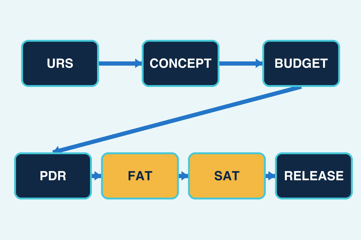
Manage procurement as connected gates from URS and RFQ through maintenance. Each stage verifies what was decided before it, and changes return to the affected earlier evidence.
URS and RFQ: define the use and the acceptance evidence
The buyer provides approved product models and drawings, revision, datum scheme, tolerances, process conditions, machine interfaces, variants, environment, safety requirements and handover deliverables. Mark unresolved points as unresolved, with an owner and decision gate. Require quotations to include a concept, assumptions, exclusions, schedule, verification plan, maintenance proposal and change-control basis.
Datum and locating-concept review
Trace each product requirement to its restraint points. Review degrees of freedom, reaction, clamp sequence, debris escape, unloading, surface damage and misload. Include the equipment builder to confirm machine coordinates, robot access, utilities and guarding interfaces.
Tolerance and error-budget review
Show the functional loop before tightening individual component tolerances. Do not specify a tolerance that cannot be verified; state the measurement reference, instrument, temperature and assembly state. For shims, eccentrics, adjustable locators or replaceable bushes, define adjustment, locking, tamper control and re-verification.
Design review and prototype or PDR
Review drawings, native CAD, BOM, materials, treatment, purchased items, sensors, I/O, pneumatic or hydraulic circuits, maintainability, safety and inspection plans—not only the three-dimensional model. Use a prototype or preliminary design review to close contact, deformation, usability and detection uncertainties before committing to final manufacture.
FAT: collect supplier-side evidence
Use golden and worst-case parts to verify seating, clamping, dimensional results, measurement, poka-yoke, abnormal response, repetition, cleaning, replacement and data capture. Put unresolved items into a punch list with an owner, due point and explicit SAT retest condition.
SAT: close the real interfaces
SAT is not a copy of FAT. Test with the actual machine, utilities, environment, chips, materials, operators and upstream or downstream systems. Include machine coordinates, robot motion, production interfaces, data capture and recovery.
Release pack, preventive maintenance and change control
The release pack should include approved drawings, native CAD and exchange files, BOM, purchased-part references, circuits, I/O, PLC/HMI/robot/inspection software, settings backups, calibration and inspection records, FAT/SAT evidence, operating and cleaning instructions, maintenance procedures, spare-parts list, training evidence and revision history.
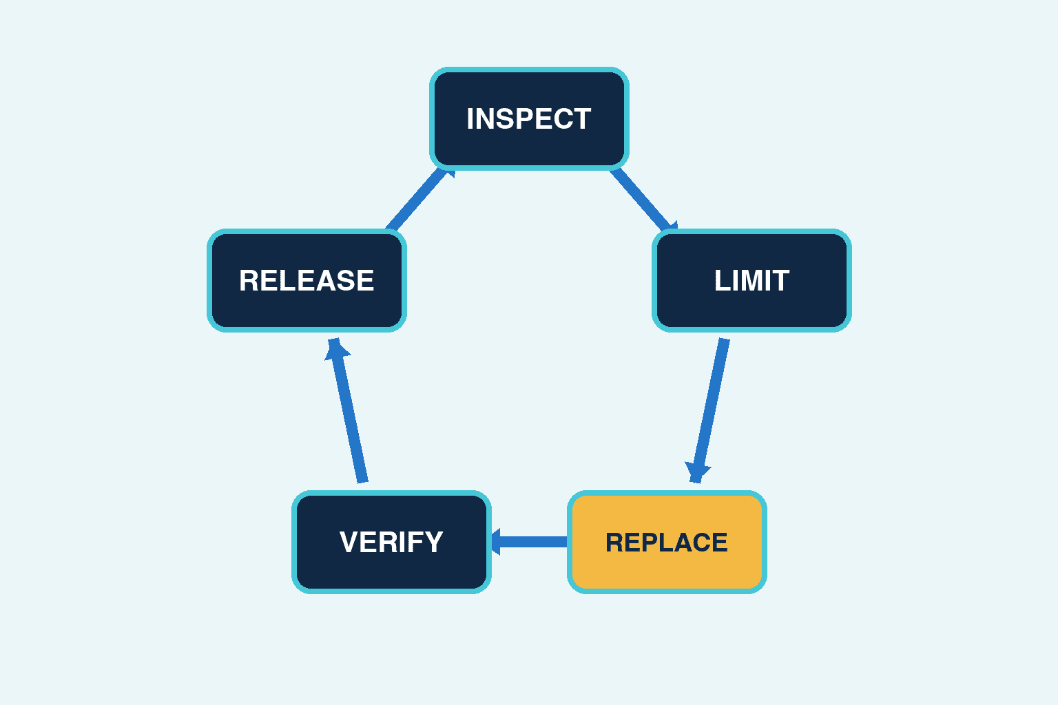
Preventive maintenance must state what is checked, by what method, when replacement is required, and what must be reverified after replacement. Change control should connect product, fixture, equipment and software changes and reassess datum, error, measurement, spares, documents and training.
Put a responsibility matrix in the RFQ
Ambiguous responsibility can delay launch as much as a technical defect. Adapt the following draft to the contract and name the party that creates, reviews, approves or supplies information.
| Deliverable or decision | Buyer | Fixture supplier | Equipment builder | Quality team |
|---|---|---|---|---|
| Product requirement and datum approval | Lead and approve | Technical review | Interface review | Tolerance and inspection review |
| Locating and clamping concept | Provide need | Lead | Check interference and machine link | Review measurement impact |
| Error budget | Approve risk and requirement | Justify fixture contributors | Justify equipment contributors | Uncertainty and decision rule |
| Safety and ergonomics | Provide use case and approve | Address fixture hazards | Integrate machine safety | Support audit and records |
| FAT | Supply parts, witness, approve | Plan, execute, correct | Simulate connection | Approve measurement and decision |
| SAT | Coordinate site and approve | Correct fixture | Integrate machine and recovery | Approve real-environment measurement |
| Release and spares | Receive and control configuration | Deliver records and spares | Deliver equipment software and circuits | Retain calibration and inspection evidence |
| Change control | Raise change and decide | Analyse impact and revise fixture | Analyse equipment impact | Define revalidation scope |
Avoid ending with vague terms such as “support.” Distinguish the maker, reviewer, approver and information provider. Final approval of the product datum, the acceptance decision rule and whole-machine safety responsibility should be clear before contract award.
RFQ checklist for production, inspection and welding fixtures
Product and process information
- Part number, revision, approved two- and three-dimensional data, material and surface condition
- Datum scheme, geometrical tolerances, critical characteristics and inspection method
- Production, inspection or welding use and the adjacent processes
- Variants, left/right versions, changeover and wrong-model prevention
- Process force, welding sequence, heat, chips, oil, dust and cleaning conditions
- Installation site, machine, utilities and communication interfaces
Fixture concept
- Locating and clamping elements that restrain each degree of freedom
- Contact material, hardness, treatment and replaceability
- Controls for datum damage, deformation, marks and contamination
- Rationale for manual, pneumatic or hydraulic operation and safe abnormal state
- Poka-yoke, seating, clamping and variant-confirmation sensing
- Cleanability, blow-off, chip/spatter escape and drainage
Accuracy, measurement and acceptance
- Error budget, assumptions and connection to product tolerances
- Measurement reference, instruments, uncertainty and decision rule
- MSA characteristics, operators, parts, repetition and environment
- Golden, known nonconforming and worst-case parts
- FAT and SAT tests, evidence and punch-list closure
- Verification at new state, after adjustment, at wear and after replacement
Safety, service and handover
- Hazards, guards, interlocks, emergency response and residual pressure
- Posture, reach, lifting, pinching and sharp edges
- Wear parts, spares, standard components, local availability and lead-time risk
- Inspection, cleaning, replacement and restoration instructions
- Drawings, native CAD, BOM, circuits, I/O and software
- Backup and restoration, training, warranty, support and change control
Quantitative acceptance-table template
Every number below is an entirely illustrative example of table structure. None is an industry rule, recommendation or TOMAS TECH guarantee. Replace each with a value justified by the product drawing, process risk, measurement capability, environment and safety requirement.
| Acceptance item | Illustrative requirement | Illustrative test condition | Evidence |
|---|---|---|---|
| Repeatability of reference position | Range no greater than 0.030 mm | Ten illustrative parts loaded three times each | Raw data, temperature, instrument ID |
| Clamping deformation | Before/after difference no greater than 0.040 mm | Five illustrative thin-sheet parts | Position-by-position comparison |
| Misload detection | Stop all eight illustrative misload cases | Wrong hand, missing item, reversed load and others | I/O log and alarm history |
| Cycle time | Illustrative target no greater than 45 seconds | Actual operator and equipment | Time record and video |
| Datum change after durability | No greater than 0.050 mm after illustrative test | After an illustrative 5,000 cycles | Before/after data and wear photographs |
| Restoration | Illustrative replacement within 60 minutes | Use released spare and instruction | Work record and repeat acceptance |
Pair the value with part condition, direction, instrument, environment, repetition method, raw data and decision authority. For results near a limit, apply the project’s ISO 14253-1-based decision rule and do not permit repeated measurements until a convenient value appears.
Define wear parts and the spare strategy while the fixture is new
Locating pins, bushes, rest pads, clamp tips, seals, hoses, sensors, cables and springs do not share one life. For each, define failure mode, inspection, replacement limit, replacement effort, post-replacement verification and stock class.
Classify spares by downtime impact and replenishment lead time, not as one unspecified set. Locally manufacturable parts need released drawings, material, heat treatment, surface treatment and inspection requirements. Purchased components need exact references and an alternate-approval procedure. Sensors and controllers that require dedicated software need configuration backups and a restoration test.
Convert wear limits from subjective appearance to measurable indicators where possible: dimension, play, holding force, sensing margin, leakage or surface condition. Connect inspection records to product defects and downtime. After replacement, reconfirm datum restoration, clamping, poka-yoke and the necessary MSA characteristics.
Commercial conditions for sourcing fixtures in Thailand
Compare design reviews, prototypes, FAT, installation, SAT, training, documentation, spares, travel, change work and warranty on the same boundary—not only the initial price. A low quote that excludes evidence or native data can create additional cost and launch risk later.
Link payment milestones to approvable deliverables such as concept approval, detailed design approval, PDR closure, FAT acceptance, SAT acceptance and receipt of final records. A change order should record not only price and schedule but also the affected error budget, acceptance tests, spares and documentation.
Thailand BOI reported H1 2026 approvals of 1,300 projects worth about THB 1.31 trillion, including THB 17.2 billion for machinery upgrades, digital technology, automation and robotics. This is macro context and does not mean that an individual fixture is eligible. See the BOI announcement.
The BOI Investment Promotion Guide states that qualifying automation or robotics efficiency-enhancement projects can receive a three-year corporate income tax exemption capped at 50% of eligible investment, or 100% where qualifying domestic automation linkages reach at least 30%. Confirm current applicability and conditions directly with BOI before budgeting. Do not assume a stand-alone fixture automatically qualifies.
For the broader delivery and acceptance-gate context, read automation project failure risks in Thailand manufacturing. For the interface between fixtures, operators and robot applications, see the collaborative robot implementation guide for Thailand.
Frequently asked questions
What information is essential for a jig design and manufacturing quotation?
Provide approved two- and three-dimensional product data, revision, datums, geometrical tolerances, process conditions, variants, machine interfaces, environment, safety, FAT/SAT and release-data requirements. Label unresolved items and assign their owner and decision gate. Compare concepts, error budgets, verification, maintenance and change scope on the same basis as price.
Does the 3-2-1 principle always make a locating fixture stable?
No. It is a useful rigid-body constraint concept, but thin sheet, compliant parts, rough cast surfaces and pre-weld assemblies can deform at the contacts. Analyse contact stiffness, load and datum stability, and consider contour, multi-point, equalised or floating support as the application requires.
What ratio should fixture tolerance have to product tolerance?
There is no universal ratio. Create an error budget for locating, clearance, deformation, equipment, temperature, wear and measurement uncertainty. Define Cpk, GR&R, accuracy ratios and tolerance allocations from the project risk and evidence; do not impose an uncited threshold as a universal rule.
What parts should be used at inspection-fixture FAT?
Use traceable golden parts together with known nonconforming, near-limit, shape-variation and misload conditions. Include measurement uncertainty, the decision rule, operators, environment and raw data. Move only the items that genuinely require the installed machine to an explicit SAT closure list.
What should welding-fixture maintenance prioritise?
Inspect datum rests, locating pins, clamp tips, spatter protection, grounding, utilities, sensors and replaceable elements according to failure mode. A change to weld sequence or heat input can change shrinkage even when the fixture is unchanged, so treat it as a process change requiring revalidation.
Conclusion: connect six records into one acceptance case
Successful jig design and manufacturing is more than the delivery of accurate machined components. Connect the product datum, locating and clamping, error budget, MSA and acceptance, wear and maintenance, and controlled release records. Carry that evidence through URS/RFQ, concept review, design, PDR, FAT, SAT and maintenance. The result is a reference that remains recoverable through production variation, replacement and product revision.
If you are still framing an RFQ or acceptance plan for a production, inspection or welding fixture in Thailand, you can consult TOMAS TECH at the planning stage. We can help organise datums, responsibilities, verification and handover conditions before every drawing is final.
References
- ISO 5459:2024 — Datums and datum systems
- ISO 1101:2017 — Geometrical tolerancing
- ISO 286-1:2010 — ISO code system for tolerances on linear sizes
- ISO 14253-1:2017 — Decision rules for conformity
- ISO 1938-1:2026 — Plain limit gauges
- NIST — Gauge R&R and measurement-process characterization
- OSHA 1910.212 — General requirements for all machines
- Thailand BOI — H1 2026 investment approvals
- Thailand BOI — Investment Promotion Guide


