


When automating transport, pressing, or positioning processes in Thai factories, if you select an electric rod actuator based solely on “stroke and maximum thrust,” you are likely to encounter problems during commissioning. The required force differs between horizontal and vertical applications, and the usable range for the same thrust changes depending on speed and duty ratio. If your mechanism applies a lateral load to the actuator rod tip, you may need a guide even if the thrust chart shows sufficient margin. This article is intended for those responsible for creating equipment specifications, and clarifies the sequence for organizing load conditions, the boundaries between control and safety, and the specific items to confirm in the RFP, FAT, and SAT. The numerical examples are hypothetical for calculation procedures and do not guarantee the performance of any specific model.
Before Selecting an Electric Rod Actuator, Define “What Will Be Moved” on a Single Sheet
An electric rod actuator is a device that converts the rotation of a motor into linear motion, moving or pressing a workpiece with a rod or similar component. However, even if the requirement is simply to “move 100 mm,” the job differs greatly depending on whether you are horizontally feeding a jig, vertically lifting a heavy door, or continuously pressing a product with a constant force. If you select a model first, you may later need to add requirements for guides, brakes, speed, heat, or wiring, making it impossible to compare quotations fairly.
On your initial sheet, include the workpiece mass, direction of movement, mounting orientation, actual stroke, stop positions, need for pressing, cycle, operating hours, surrounding environment, and the state during power outages. Be sure to include not only the workpiece, but also the mass of brackets, end effectors, moving cables, and any following parts. In your process diagram, show where the workpiece’s center of gravity will be at both the extended and retracted ends. Discussions about electric rod actuator selection proceed much faster when everyone refers to this load condition table and mechanism diagram as common inputs.
Especially, clearly distinguish between “positioning” and “applying force to an object.” The design where the positioning endpoint is received by a hard stopper is different from a design where the controller detects contact via a pressing operation; this affects set values, collision risks, and acceptance tests. The SMC LEY operation manual also cautions that when pressing for holding, you should use the pressing operation and avoid collisions caused by positioning operations. Note that this explanation is specific to the LEY series and does not represent common specifications for other manufacturers’ products. Source: SMC LEY Operation Manual
Do Not Determine Stroke Based Only on the Workpiece’s Travel Distance
The required stroke should be considered as the actual distance the workpiece moves plus approach positions, clearance, allowance for gripping or pressing, and the path for homing. For example, even if the process is to move a workpiece 100 mm, if you need to fully retract the end effector during changeover, the required mechanical stroke will exceed 100 mm. Conversely, if you use the catalog’s maximum stroke in its entirety, you will have no margin to absorb stop errors or mechanical interference. Clearly distinguish on your drawings between the usable range and the mechanical limits.
In your selection table, have separate columns for “effective travel distance,” “pressing start position,” “home and standby positions,” “required mounting dimensions,” and “clearance to obstacles.” Increasing the stroke length affects the actuator’s body size, deflection, tip support, speed, and cycle time. The SMC operation manual notes that for long strokes with one-sided fixed horizontal mounting, a support bracket may be required, and that high-speed operation can cause end vibrations resulting in bending moments. In your specification, include not only the “selected stroke” but also the support conditions during extension. Source: SMC LEY Operation Manual
Do not mix up requirements for “repeatability,” “absolute position deviation,” and “workpiece position after assembly.” The catalog’s repeatability specification does not guarantee the finished dimensions of the entire process. First, determine the process-side tolerance, including jig deflection, sensor detection width, mounting references, and workpiece variation. If you specify a value, also specify the measurement location, load, direction, temperature, and number of trials. If you only test approach from one direction, you may overlook differences when reversing.

Separate Load Calculations for Horizontal, Vertical, and Inclined Installations
In horizontal transport, most of the gravitational force is borne by the guide or support surface, and the actuator’s axial direction only needs to overcome acceleration, friction, and external forces. In vertical lifting, the force required to lift the mass is added to the acceleration force. For downward movement, braking and drop prevention during power outages become issues. For inclined installations, separate the gravitational component along the axis from the lateral component borne by the guide. Do not simply call the workpiece mass the “required thrust”—record the worst-case position and direction of movement.
A simple formula for initial consideration is:
Axial required force ≈ mass × axial acceleration + axial gravitational component + friction/external process force.
However, you cannot ignore static friction at startup, cable resistance, pressing reaction force, inertia at stop, or mechanism efficiency. For example, if you assume lifting a 10 kg mass vertically, the gravitational component is about 98 N, but you must not use only this value as the required rated thrust. Add acceleration, friction, safety design, and holding during power outages separately. The 10 kg and 98 N here are calculation examples, not selection values.
The manufacturer’s allowable load tables vary depending on orientation, speed, motor, lead, stroke, and guide conditions. The SMC LEY manual notes that for some models, the definition of maximum horizontal workpiece load assumes external guide conditions, and for vertical use, you must check the catalog values for the selected model. Do not apply horizontal values to vertical applications. In your quotation request, clearly state “which guide supports the workpiece” and ask the manufacturer to provide the selection rationale. Source: SMC LEY Operation Manual
Match Thrust and Speed at the Same Operating Point
Do not assume you can use separate maximum values such as “maximum thrust 300 N” and “maximum speed 500 mm/s” simultaneously. In most linear motion systems, motor, lead, power supply, acceleration/deceleration, and thermal constraints are interrelated. What you need to compare is the actual operating point that simultaneously satisfies your load, speed, acceleration, travel distance, and pressing time. Enter your conditions into the candidate model’s speed vs. load table or selection software, and record the model, settings, and version. Festo provides a sizing tool for electric actuators, but you must still compare the results with your actual implementation conditions. Source: Festo Sizing Tool
Cycle time cannot be determined by “distance ÷ maximum speed” alone. For short moves, acceleration and deceleration may prevent reaching maximum speed. Settling time after stopping, workpiece gripping, pressing hold, sensor confirmation, and PLC response must also be included in the process time. During FAT, measure cycle time using actual workpieces and jigs, under both normal and worst-case loads. Do not confuse the controller’s set speed with the process takt time.
For pressing processes, distinguish between “thrust during movement” and “force maintained after contact.” If your design switches from high-speed movement to low-speed pressing just before contact, check whether the variation in switching position and workpiece differences can be absorbed. The SMC LEY manual explains the relationship between pressing speed, force setting, arrival detection signal, and pressing start position, and for this series, notes that the start position should be set a certain distance from the workpiece. Do not generalize these values to other models; always follow the candidate machine’s operation manual. Source: SMC LEY Operation Manual
Confirm Duty Ratio, Continuous Pressing Time, and Ambient Temperature
Even if the cycle is feasible, long-term operation may exceed thermal limits. In your specification, include the number of moves per cycle, each travel distance, pressing force, pressing duration, standby time, cycles per hour, and continuous operation time. A model that can meet maximum conditions for a short time is not the same as one that can repeat those conditions continuously. Also include ambient temperature, panel temperature, and any covers that may hinder heat dissipation.
The SMC LEY manual contains tables showing allowable duty ratios and continuous pressing times for specific models, depending on pressing force and ambient temperature. Therefore, simply confirming that “pressing force is within range” is not sufficient. You must check the actual pressing and rest times against the table for the specific model. The values in these tables are model-specific and are not universal upper limits for all electric rod actuators. Source: SMC LEY Operation Manual
For lines with fluctuating utilization rates, indicate not only the average but also periods of concentrated operation. If you plan to shorten the takt time in the future before mass production ramp-up, select separate operating points for the current and future targets. Rather than setting a uniform “margin of X%,” it is more accurate to list how much margin you have for each constraint. Check thermal, speed, thrust, service life, positioning accuracy, and power supply capacity separately.
Don’t Overlook Lateral Loads and Moments at the Rod Tip
Even if the axial thrust of the actuator rod is sufficient, applying lateral forces or torsion at the tip can shorten the lifespan of the bearings and guides. This can occur, for example, when a workpiece is mounted on a cantilevered plate, when a jig becomes eccentric during transport, when the pressing surface contacts at an angle, or when external guides are not assembled in parallel. Always indicate the distance from the workpiece’s center of gravity to the centerline of the rod, and estimate the bending moment for both extension and retraction. Drawing load arrows on the design drawings helps reduce oversights.
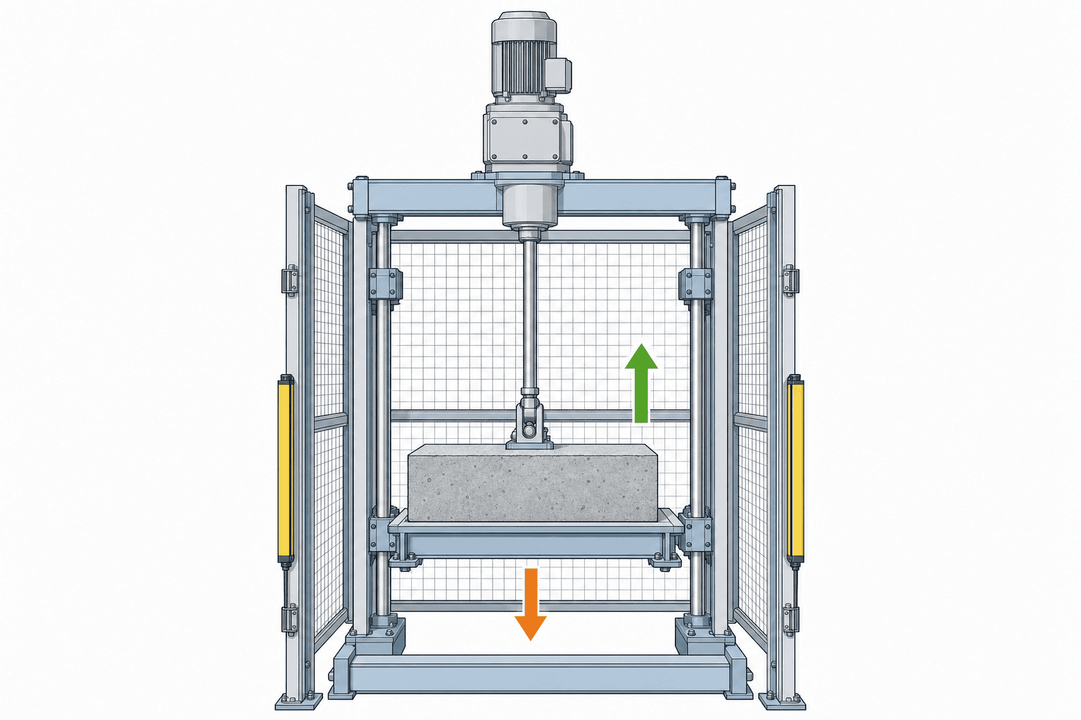
Countermeasures include using models with guide rods, supporting the workpiece with external linear guides, allowing necessary degrees of freedom at connection points, and managing mounting rigidity and parallelism. The choice depends on the mechanism. SMC distinguishes between rod types and guide rod types, and THK’s selection materials show how to reflect loads and moments on guides in service life calculations. Consider “the force the rod can push” and “the force that can guide the workpiece” as separate evaluation items. Source: SMC LEY/LEYG Operation Manual, Source: THK Selection Materials
Even when using external guides, ensure that mounting errors between the cylinder and guide do not generate internal lateral forces. Include assembly sequence, adjustment methods, allowable misalignment, and measurement standards in the design documentation and inspection criteria. Even if the load appears linear on paper, resistance can increase if the installation reference surfaces differ on site. If the design allows for manual movement across the full stroke, checking for catching under no load is useful for initial inspection. However, always prioritize actual equipment safety procedures and manufacturer instructions.
Compare Combinations of Lead, Motor, and Guide
Selecting an electric cylinder is not just about choosing motor output. Changing the screw lead alters the relationship between travel speed and the axial force available at the same motor speed. The presence or absence of a reducer or brake also affects stopping and holding performance. Do not simply compare “high-speed” or “high-thrust” labels; instead, request that each candidate be presented with a consistent configuration for the required operating point.
Selection tables should include manufacturer, model, motor/controller, lead, guide, stroke, rated/peak conditions, speed, pressing range, repeatability, power supply, communication, brake, cable, and mounting dimensions. The information provided by manufacturers varies by product series. For example, IAI publishes a list of rod-type series, and SMC’s LEY-E has a web catalog for product series. Since the series name alone does not determine the final specification, always request the exact model number and the latest documentation for each candidate as part of the quotation. Source: IAI Rod Type List, Source: SMC LEY-E Web Catalog
For detailed consideration of ball screw selection, service life, bearings, and backlash, refer to the Ball Screw Selection Guide for Thai Factories. The focus of this article is not on the screw alone, but on the decision to integrate rod-type actuators and their control into the process. Even if the mechanism is already decided and only the drive system is being selected, do not omit consideration of load direction, guides, heat, and power failure conditions.
Decide Control Method Based on PLC Responsibility Boundaries
The required number of positions, movement profiles, presence of pressing, product changeover, and traceability requirements all affect the necessary controller functions. For simple two-position movement, I/O alone may suffice. However, if position or force must change for each product, determine recipe numbers, setpoint management, change authority, and how to acquire actual values. Do not judge compatibility by communication protocol name alone; instead, create a signal table for the commands sent by the PLC and the completion, error, and home status signals returned.
“Movement complete” and “pressing force has reached the target” are not the same signal. According to the SMC LEY manual, the INP signal during pressing operation is related to the force threshold, and if pressing is not completed within the specified distance, a different status is indicated. For each candidate device, confirm the meaning of signals and transitions during abnormal conditions on the actual equipment. Set timeouts on the PLC side to prevent endless pressing in the event of undetected sensors or missing workpieces. Source: SMC LEY Operation Manual
The selection objectives for electric cylinder motors differ from those for inverter control of conveyors or pumps. For discussions on overall line speed adjustment or multi-axis synchronization, refer to Differences Between Servo Control and Inverter Control, and clarify what needs to be closed-loop controlled for each axis. Here, prioritize the required position, speed, force, and behavior at stop for the process, rather than just the terminology.
Include Power Failure, Emergency Stop, and Restart States in the Design
For vertical axes and pressing processes, always consider what happens to the workpiece when the power is cut. Do not take motor holding torque or mechanical self-holding for granted as safety functions. A comprehensive risk assessment of the entire system—including brakes, mechanical stoppers, fall prevention, guards, and interlocks—is necessary. SMC’s operation manual also requires confirmation of measures to prevent falling or runaway of moving parts during maintenance and instructs to cut the power supply. Source: SMC LEY Operation Manual
Recovery from emergency stop is not simply a matter of re-energizing and moving. Confirm whether home position information is retained, whether the workpiece is held at the stop position, whether pressing is released, and whether peripheral equipment is in the same state. Do not determine the safety circuit configuration based solely on the actuator’s function table; design it based on the hazards of the entire machine and applicable standards. In the RFP, do not just write an abstract statement such as “must hold during power failure”; specify the object to be held, posture, maximum mass, duration, recovery operation, and verification method.
Cables and power supply are also part of the facility requirements. Diagram the required capacity and routing for actuators, controllers, I/O, communication, protective grounding, and power supply. Check the bending of moving cables, connector protection, panel temperature, surge and noise, and replacement space for maintenance. The SMC LEY operation manual lists power supply conditions and wiring precautions for specific configurations, so confirm with the candidate model and controller combination. Do not apply the same voltage to different products. Source: SMC LEY Operation Manual
Reflect Thai Factory Environment and Maintenance System in Specifications
It is not possible to generalize that a particular model is always suitable just because it is a Thai factory. What must actually be checked are the installation location’s temperature, dust, oil mist, moisture, cleaning agents, vibration from surrounding equipment, power quality, and maintenance staff response time. Compare the environmental specifications of the product series with the implemented state including covers and seals. Even in high-humidity areas, whether condensation occurs depends on machine downtime and air conditioning operation, so on-site condition checks are necessary.
To shorten recovery time after failure, parts supply and settings backup should also be selection items. Confirm the locally available models and lead times for the main unit, controller, cables, brakes, and sensors, as well as origin reset and program recovery procedures during replacement. Decide at the time of order whether English/Thai panel labels, fault code lists, and maintenance procedures are required. These cannot be measured by product performance claims and should be specified in the RFP as part of operational design.
For maintenance inspections, adopt the items specified in the candidate product’s maintenance manual, such as mounting looseness, abnormal noise, temperature, grease, cables, end contact, and changes in pressing force. Do not set inspection intervals uniformly; instead, set them based on product specification, cycle count, environment, and failure impact. Also, work backward from the desired failure analysis to determine which values can be recorded by the PLC or higher-level system.
RFPs Should Include “Values,” “Conditions,” and “Criteria” Together
If a request for quotation only states “stroke 200 mm, thrust 500 N, as fast as possible,” each company will respond under different conditions, making price comparison difficult. What is needed are the measurement conditions and pass/fail criteria for each value. For example, include “maximum movable mass including actual workpiece and jig,” “position during vertical ascent,” “travel distance,” “required cycle time,” “pressing force and holding time,” “number of repetitions per hour,” and “ambient temperature” in the same table. Note that the 200 mm and 500 N listed here are examples, not recommended values.
The minimum RFP items are as follows:
| Item | Content to Specify | Evidence Required in Response |
|---|---|---|
| Workpiece & Orientation | Maximum/minimum mass, center of gravity, horizontal/vertical/inclined, tip jig | Load diagram, guide configuration |
| Operation | Effective stroke, number of positions, speed, acceleration/deceleration, cycle time | Speed/load selection results by model |
| Contact | Pressing force, contact speed, holding time, force evaluation | Model-specific pressing range and duty ratio |
| Accuracy | Measurement position, tolerance, load, temperature, repeat conditions | Measurement method and acceptance criteria |
| Safety | Workpiece state during power failure, emergency stop, and recovery | Countermeasure diagrams for both mechanical and control aspects |
| Connection | PLC, I/O, communication, power supply, cable length | Signal table, wiring diagram, power consumption |
| Maintenance | Environment, replacement parts, settings backup | Recommended inspections, local supply and recovery procedures |
Request candidate manufacturers to provide catalog versions of applicable models, input values for selection calculations, and exclusion conditions. If the response only states “within allowable range,” confirm at which operating point and for which rated/peak values the judgment was made. In the comparison table for multiple proposals, include not only price and delivery time, but also additional guides, brakes, control man-hours, and spare parts required on the equipment side. A low-cost main unit does not necessarily mean low total equipment cost.
In FAT, Reproduce the Selection Conditions with Actual Workpieces
FAT (Factory Acceptance Test) is not a manufacturer’s demonstration, but an opportunity to verify the operations described in the RFP using the actual equipment configuration. Reproduce the maximum and minimum workpiece mass and center of gravity, lateral load at the extended end, dimensional variation of the pressing target, continuous operation, and homing. During testing, record travel time, stop position, overshoot upon contact, abnormal signals, power consumption, and temperature changes. Design the duration of temperature tests to reflect the actual duty ratio.
For positioning tests, agree in advance on how many times to test, where to measure, and from which direction to approach. For pressing tests, use measurement devices such as force gauges to confirm the actual force on the workpiece side, and do not assume the controller’s set percentage directly reflects the measured force. Even in SMC LEY documentation, product-specific accuracy conditions are specified for pressing force. If the required accuracy is strict, consider including an external force sensor. Source: SMC LEY Operation Manual
Abnormality testing is also important. Simulate missing workpieces, workpiece jamming, sensor failure, communication loss, power outage, and emergency stop, and record whether the actuator and peripheral devices stop safely, which alarms remain, and how operators recover. For dangerous tests on actual equipment, decide safe simulation methods in advance. Any unresolved FAT items should be handed over to SAT with responsible persons and deadlines specified.

In SAT, Confirm Installation Deviations and Operation
In SAT (Site Acceptance Test), the factory foundation, mounting surfaces, external guides, power supply, PLC, and upstream/downstream equipment are added. Even actuators that passed FAT may experience load changes if the parallelism or workpiece supply position differs on site. Use actual workpieces to check cycle time and stop position under representative conditions for multiple shifts. Record measurements in the same format as FAT, and if discrepancies arise, identify whether they originate from the mechanism, control, or environment.
Including recovery training as an acceptance condition can help reduce downtime after mass production. Local staff should use procedures to perform startup after power failure, alarm reset, homing, workpiece removal, and restoration from backup settings. Prioritize safety operations according to the equipment’s risk assessment and site regulations. SAT completion conditions should include the handover of drawings, electrical diagrams, PLC signal tables, backup settings, spare parts lists, inspection sheets, and training records.
Constructing Selection Conditions with Three Hypothetical Processes
Even with the same rod type, the order of items to check first changes depending on the process. The following is not a recommendation of models, but an example of thinking to identify omissions in specifications. For each process, separate columns for “known items,” “items not yet measured,” and “items to request from the manufacturer.” Do not enter estimated values into the confirmed column without measurement, as this reduces selection errors.
Process A: Horizontally transferring a jig. The workpiece is supported by an external linear guide, and the electric actuator mainly drives in the axial direction. Here, first check the required effective stroke, reciprocating time, guide friction, cable drag resistance, and jig interference at the extended end. Do not assume “light load because it’s horizontal”; illustrate whether the center of gravity of the jig and workpiece is offset at the extended end. In acceptance testing, attach the heaviest jig and measure the time for forward and backward movement, stop position, and any catching during operation. Also inspect the parallelism of the guide and actuator during installation.
Process B: Lifting a product vertically. Since gravity always acts in the transport direction, design not only for the required force during ascent but also for control and stop state during descent. Decide whether the product needs to be held during a power outage, where to recover after an emergency stop, and whether there are mechanical measures to prevent the workpiece from falling during replacement. Provide the manufacturer with the maximum mass, acceleration/deceleration, stroke, cycle, and power outage requirements as a set. In FAT, in addition to normal operation, safely simulate power loss and emergency stop; in SAT, reconfirm using the actual mounting surface and guide.
Process C: Pressing a product under constant conditions. If the contact position varies for each product, separate the movement to contact from the pressing after contact. Specify the required force, allowable variation, holding time, rest time until the next cycle, and the hardness of the contact surface, and decide how to measure force on the workpiece side. Do not equate set values with actual force; design acceptance tests using a force gauge. Changes that extend pressing time also affect heat and duty ratio, so do not treat them as simple PLC timer changes—recheck the model’s allowable conditions.
What this comparison of three processes shows is that even if you fill in the same “stroke” and “thrust” columns, the basis for selection will not be the same. In Process A, guide and cycle time come first; in Process B, gravity and safety during stops; in Process C, contact force and duty ratio are the priorities. If you want to standardize the same part across multiple processes, do not just select the most severe single condition—ensure all three operating points fall within the candidate’s allowable range. Even if standardization helps with maintenance or inventory, it cannot justify compromising equipment safety or performance.
Scope of Recalculation When Specifications Change
It is not uncommon for workpiece weight, jig shape, cycle time, pressing time, or mounting orientation to change during mass production preparation. Even a single change can affect not only thrust, but also speed, acceleration, moment, heat, behavior during power outage, and cable routing. Record the before-and-after values, reasons, approvers, and re-verified items on the change sheet. Do not assume that testing in SAT is sufficient for changes after FAT approval; for significant impacts, retest in the factory before shipment. Align PLC setting backups and drawing revisions to reduce “differences between actual equipment and documentation” during maintenance.
Do not conclude change sheet evaluation with “the actuator moved, so it’s OK.” For example, if changing the jig increases mass, recalculate required force during acceleration, inertia at stop, moment on the guide, and positional deviation during pressing, even if the stroke is unchanged. If shortening the cycle time, review not only the maximum speed but also acceleration/deceleration sections, pressing time, rest time, and temperature trends. For workpiece dimension changes, check whether the pressing start position or contact surface angle has changed. Color-code the affected columns in the selection table for each change, and do not finalize mass production conditions as long as there are unverified columns.
Acceptance records should include not only the setting file name, but also the model, controller version, key parameters, tested workpiece, measuring instruments, measurement date, and tester. Even if values fall within the acceptance range, save how many times you measured and what the worst value was. This allows comparison with the initial state if the same actuator slows down after six months. When investigating issues during mass production, knowing the original selection conditions makes it easier to distinguish between “mechanical wear,” “setting changes,” and “workpiece changes.” Keep the record format simple enough for the site to maintain, and link drawing numbers and test sheet numbers.
The boundary between the purchaser and the equipment manufacturer should also be included in change management. If the purchaser changes the workpiece mass or cycle time, the manufacturer should present re-verification of selection conditions and any necessary additional tests. If the manufacturer substitutes the model or controller, the purchaser should receive not only an explanation of equivalence, but also updates to affected signals, safety, and maintenance procedures. Clearly specify the approver and application date for changes to prevent mixed settings between prototypes and mass production machines.
Frequently Asked Questions About Electric Actuator Selection
Can I select an actuator if the maximum thrust exceeds the required force?
No. Confirm thrust and speed at the same operating point, and separately evaluate orientation, acceleration, lateral load, duty ratio, temperature, service life, and holding during safety events. For pressing processes, separate the conditions for movement and after contact. Comparison tables listing only maximum values are useful for initial screening, but insufficient for purchase approval.
Can an electric actuator selected for horizontal use be used vertically?
Judge only after re-evaluating the model’s vertical load table, drop prevention, brake, speed, and guide. Do not simply apply the horizontal allowable mass to vertical use. Also design for what happens to the workpiece during power loss and emergency stop. For change approval, attach the manufacturer’s model-specific documentation and a safety verification for the entire system.
Can pressing force be guaranteed solely by the controller’s set value?
No. The set value and the actual force transmitted to the workpiece are not the same. Check the model-specific pressing range, speed, temperature, duty ratio, mechanism friction and deflection, and measure with an external force gauge if necessary. If the process requires strict tolerance, design to include a force sensor or mechanical compensation. Fix measurement conditions for comparison in FAT and SAT.
Can a jig be mounted directly to the actuator rod tip?
If the jig’s center of gravity or reaction force from contact is offset from the axis center, lateral load or moment will occur. Check the model’s allowable values and service life calculations, and use an external guide or guided rod type if necessary. Even after supporting the tip, check that assembly errors do not increase lateral force.
What should be compared in electric actuator quotations?
Look at the total system cost, including not only the actuator body, but also the controller, guide, brake, cables, mounting hardware, PLC implementation, commissioning, spare parts, and maintenance. At the same time, compare the basis for each candidate meeting the required operating points, environmental conditions, local supply, and failure recovery methods. Initial cost alone does not reflect operational downtime risk.
Summary
Electric actuator selection does not start with matching stroke and maximum thrust, but with translating workpiece, orientation, simultaneous force and speed conditions, duty ratio, lateral load, control, and safety into a single process specification. Attach measurement conditions and evaluation methods to the RFP, verify actual workpiece operation in FAT, and confirm on-site installation and recovery in SAT. Read manufacturer selection tables with model-specific conditions, and do not substitute calculation examples for product guarantees.
Even if specifications for transfer or pressing axes in a Thai factory are not yet finalized, having a load diagram and cycle time table allows you to organize the key selection points. For comprehensive consideration—including external guides, PLC signals, safety, and FAT/SAT items—consult TOMAS TECH.


