


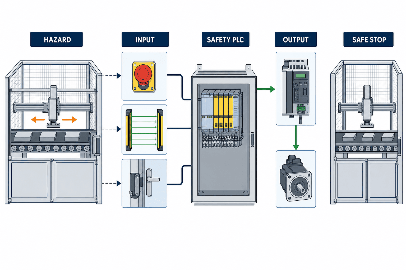
The most consequential mistake in a safety PLC implementation is assuming that a certified controller proves the safety of the complete machine. A safety PLC is a critical component, but machine-level confidence comes from a connected evidence chain: hazard, safety function, required PLr or SIL, architecture and software, verification, validation, and repeatable FAT/SAT results. This guide shows manufacturers in Thailand and ASEAN how to buy that chain as an engineering deliverable rather than buying hardware first and discovering the evidence gap at acceptance.
Executive answer: procure the safety-function evidence chain
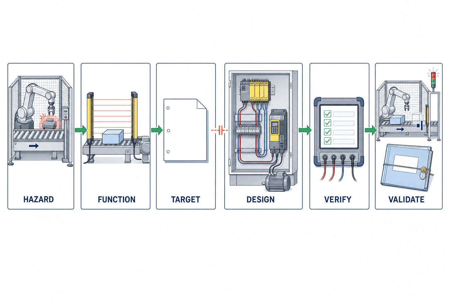
The contracted outcome should be: identify hazards; define safety functions; establish the required target using a declared method; design and implement sensors, logic and actuators; verify the design; validate the installed functions; and retain evidence that another competent reviewer can reproduce.
A strong safety PLC project therefore delivers more than source code. It links the risk assessment, Safety Requirement Specification (SRS), cause-and-effect matrix, schematics, architectural evaluation, software specification, parameter baseline, verification records, validation plan, FAT/SAT reports, residual risks and maintenance instructions.
If this sequence is broken, even a capable safety CPU, dual-channel inputs and safety drives leave unanswered what hazard is controlled, what state must be reached and within what time. When the evidence chain is explicit, buyers can compare suppliers not only by price, I/O count and network, but also by compliance with the requirement, diagnostics, change control, testability and the ability to keep evidence current during maintenance.
What the 17 September 2026 certificate announcement means
On 17 September 2026, Mitsubishi Electric announced that its MELSEC iQ-R safety programmable controller had obtained an EU type-examination certificate under the EU Machinery Regulation. The release says the product can combine general and safety control and describes cybersecurity measures. Claims such as “one of the first” and “first for its FA business” should remain attributed to Mitsubishi Electric, not presented as independent market rankings.
The useful signal is not that one product can complete conformity work automatically. The current consolidated Regulation (EU) 2023/1230 applies from 20 January 2027, and the Commission’s machinery material highlights cyber-safety where compliance-relevant software and safety control systems are involved. Buyers should therefore design evidence, access control and change control at component-selection time. They should not copy the obsolete 14 January date still seen in some older presentations of the initial text.
Certification reduces uncertainty about the component’s declared scope, conditions and constraints. It does not find omitted hazards, choose PLr, correct field wiring, prove stopping distance, prevent guard defeat, validate parameters or control maintenance changes. Those obligations remain at machine and application level.
Standard PLC versus functional-safety PLC
A standard PLC can switch an output off. A functional-safety PLC is engineered and assessed to implement safety-related functions with defined integrity, diagnostic behaviour, fault reaction, development constraints and documented conditions of use.
| Topic | Standard control | Safety-related control using a safety PLC |
|---|---|---|
| Primary purpose | Sequence, quality, speed and productivity | Risk reduction through specified safety functions |
| Fault approach | Alarm and recovery are often operational choices | Diagnostics, fault reaction and safe state are design evidence |
| I/O and communication | Standard I/O and network | Safety I/O and suitable safety communication where required |
| Software | Functional testing dominates | Structured design, controlled elements, review and traceability |
| Acceptance | A successful sequence may be enough | Negative, fault, timing, reset and recovery tests are required |
| Deliverable | Program, I/O list, operator notes | Traceable evidence from hazard to validation |
Even when ordinary and safety control share a chassis or engineering environment, their authority, lifecycle and evidence must remain controlled. A speed change in standard logic is safety-relevant if it affects stopping time or protective distance.
A product page may state capability up to SIL 3 or PL e. That is not the achieved integrity of every machine function. Performance depends on the complete chain—input device, wiring, logic, communication, output element, actuator, diagnostics, common-cause measures, software, test interval and conditions of use.
Certified component does not equal compliant machine
“Stop the robot when the light curtain is interrupted” is not a complete safety function. A testable specification includes:
- person, operating mode and hazard;
- triggering device and detection conditions;
- controlled actuator and required reaction;
- defined safe state;
- total response-time budget;
- reset and restart conditions;
- required PLr or SIL and the selection rationale;
- environmental, wiring, distance and test conditions;
- verification methods; and
- installed-machine validation evidence.
Mitsubishi’s safety I/O manual also makes the important distinction that certified products do not guarantee freedom from malfunction or failure; the equipment designer must perform the risk assessment and select the necessary SIL/PL. In the cited module context, double wiring is required for a SIL 3 / Category 4 / PL e configuration. That requirement must not be generalised to every safety PLC. Record the exact module, manual revision, circuit example and constraint.
From ISO 12100 risk assessment to the safety specification
ISO 12100:2010 provides machinery risk-assessment and risk-reduction methodology. It is the current edition at research time, with revision work underway. An RFP should state the edition and define how a new edition released during the project would be handled.
Start by defining machine limits across production, setup, cleaning, jam clearing, teaching, maintenance, recovery and decommissioning. Identify hazards by task and mode: crushing, cutting, entanglement, ejection, electricity, heat, pressure, gravity and unexpected start. Consider inherently safe design and guarding before relying on safety-related control.
Then assign one ID to each safety function. Record the hazard, input, logic, output, safe state, maximum response time, reset, mode, PLr/SIL target, exclusions and test method. “Stop safely” is not specific enough; state which energy, motion and pressure must reach which condition and within what time.
1. Define the limits of the machine
Cover more than automatic production. Include setup, cleaning, jam removal, teaching, maintenance, recovery and decommissioning. Record who may approach the machine in each mode, including contractors and temporary operators. At multilingual sites, define the terminology map and physical-tag convention at this stage.
2. Identify hazards and hazardous situations
Describe hazards by task and mode, not with broad labels such as “robot present.” Examine crushing, cutting, entanglement, ejection, electricity, heat, pressure, gravity and unexpected startup. Include low-speed teaching, residual pressure after stopping and coast-down after a guard is opened.
3. Prioritise inherently safe design and guarding
The safety PLC is not the default first measure. Reduce hazardous force, remove trapping gaps, relocate service points and use fixed guards where practicable. Only then allocate interlocks, light curtains, safe-speed monitoring and other safety-related control functions.
4. Specify every safety function unambiguously
Give each function an ID and define input, logic, output, safe state, maximum response time, reset, operating mode, hazard, PLr/SIL target, exclusions and test method. Replace “stop safely” with the exact energy, motion or pressure state to be achieved.
5. Record residual risk and information for use
Do not push risk casually into procedures, training or PPE. Document why risk remains, who controls it and which changes trigger reassessment. Operating information must agree with the actual validated machine state.
ISO 13849-1 or IEC 62061: choose a coherent method
ISO 13849-1:2023 covers design and integration of safety-related parts of control systems, including software. It does not choose the application’s safety function or PLr, and it does not directly specify security measures. ISO 13849-2:2012 addresses validation by analysis and testing of safety functions, categories and performance levels. The 2012 edition is current at research time, while revision is underway.
The current consolidated edition is IEC 62061:2021+AMD1:2024+AMD2:2026 CSV. It addresses design, integration and validation of safety-related control systems and emphasises lifecycle disciplines including functional-safety planning, configuration management, parametrisation, periodic testing and appropriate independence of verification and validation. Amendment 1 was published in 2024 and Amendment 2 on 20 March 2026. The RFP should name this consolidated edition or the exact edition and amendments actually applied.
| Decision point | ISO 13849 route | IEC 62061 route |
|---|---|---|
| Target | PLr supported by a risk-based rationale | SIL requirement supported by a risk-based rationale |
| Evidence | SRP/CS blocks, data, architecture, software and validation | Functional-safety plan, subsystems, integration and lifecycle evidence |
| Tool support | SISTEMA may support structured evaluation | Suitable calculation and lifecycle tools may be used |
| Misuse to avoid | Copying PL e from a component label | Copying SIL capability from a component label |
| Shared requirement | Complete-function evidence on the real machine | Complete-function evidence on the real machine |
Do not manage a mixed project with a casual one-to-one PL/SIL conversion table. Declare which method governs each function, the interface between methods, shared components, assumptions and approval responsibility. SISTEMA can support ISO 13849 analysis, but its output is only as sound as the entered data, block boundary and operating assumptions.
Twelve mandatory requirements for a safety PLC RFP
1. Scope and responsibility boundary
Identify machines, lines, modes, modification limits and interfaces with existing equipment. Require a RACI covering risk assessment, safety specification, panel, field wiring, PLC software, drive parameters, tests, documents and training.
2. Applicable legislation, standards and editions
List destination, installation country and customer rules. Name ISO 12100, ISO 13849-1:2023, ISO 13849-2:2012 and IEC 62061:2021+AMD1:2024+AMD2:2026 CSV where applicable. Avoid an undefined promise to comply automatically with every future edition.
3. Risk-assessment method and participants
Define the workshop method, record form, approver and residual-risk treatment. Require mechanical, electrical, controls, production, maintenance, EHS and real operators to participate rather than accepting a supplier-only desktop exercise.
4. Safety Requirement Specification
Give every safety function an ID and define hazard, input, logic, output, safe state, response time, reset, mode, PLr/SIL and test method. A requirement change must point to the designs and tests that need review.
5. Hardware architecture
Break the chain into sensor, safety I/O, CPU, communication, contactor, safety drive and pneumatic/hydraulic output. Require model, firmware, certification scope, operating constraints, component data, common-cause measures, diagnostics and proof-test interval.
6. Software design rules
Define permitted safety blocks, naming, state transitions, reset, muting, bypass, stopping, restart, error handling, code review, static checks and test coverage. Verify that standard logic cannot silently alter safety parameters.
7. Parameter and engineering-tool control
Identify safety-related drive speeds, stopping-monitor times, sensor distances, filters and discrepancy times. Specify who can change them, how approval works, what is backed up and which tests follow a restore.
8. Cybersecurity and remote maintenance
Specify engineering workstations, user identity, least privilege, multifactor access where appropriate, approved remote windows, activity logs, protected backups, malware controls and end-of-support notices. A pathway that can alter safety logic or parameters belongs in the safety impact assessment.
9. Verification plan
Assign requirement review, circuit review, calculations, I/O tests, software unit tests, interface tests, fault injection and stopping-time measurement. Define sufficient independence so the author is not the only person making the acceptance decision.
10. Validation and FAT/SAT
For every safety-function ID, require normal, fault, boundary, recovery, power-loss, communication-loss, open-circuit, short-circuit, discrepancy and restart cases. Site-dependent cases not completed at FAT must be transferred explicitly to SAT.
11. Evidence format and traceability
Link requirement ID, drawing number, PLC version, parameter baseline, test case, instrument, executor, time, result, deviation, correction and retest. A photograph, signature or tick mark alone is insufficient.
12. Handover, change and maintenance
Contract for editable source, compiled backup, licences, credential transfer, BOM, spares, obsolescence notice, training, periodic proof testing, restore drills, change requests and revalidation triggers.
Treat software, parameters and change as one safety deliverable
Protective distance can depend on sensor response, PLC filtering, network update, drive reaction and mechanical stopping time. A change to any one element can invalidate the earlier result. Every change request should state the reason, affected asset and safety-function IDs, before/after source and checksum, firmware and library, changed parameters and drawings, safety impact, regression scope, approvals, rollback and installed result.
A change from one second to 1.5 seconds is not “only a value” if it affects monitoring or stopping. Online edit, forcing and bypass need permission, expiry, visible indication and audit. Remote access by an overseas OEM should be time-bound and individually attributable; restoring a backup should trigger version checks and defined tests.
This discipline is not limited to machinery shipped to the EU. Even without export, global-company internal standards, insurance requirements, accident prevention and reliable recovery after changes all require the factory to explain what changed, which safety functions were affected and what evidence supports return to service.
A bounded 90-day design and acceptance plan
This is a TOMAS TECH planning example, not a normative duration or a promise for every machine.
| Period | Work package | Exit evidence |
|---|---|---|
| Days 1–15 | Limits, hazards, documents, standards, interfaces | Approved hazard register and candidate functions |
| Days 16–30 | SRS, target method, response budget, RFP answers | Every function has an ID, target and test concept |
| Days 31–55 | Circuit, I/O, PLC, drive, HMI, diagnostics and change control | Reviewed and baselined design |
| Days 56–70 | Calculation, verification, unit/interface tests, fault injection, FAT | Major deviations closed; SAT carryovers identified |
| Days 71–85 | Installation, wiring check, stopping-time test, SAT and recovery | Installed functions and restart rules demonstrated |
| Days 86–90 | Correction, retest, training, handover and approval | Evidence ledger complete and ownership transferred |
What FAT must confirm
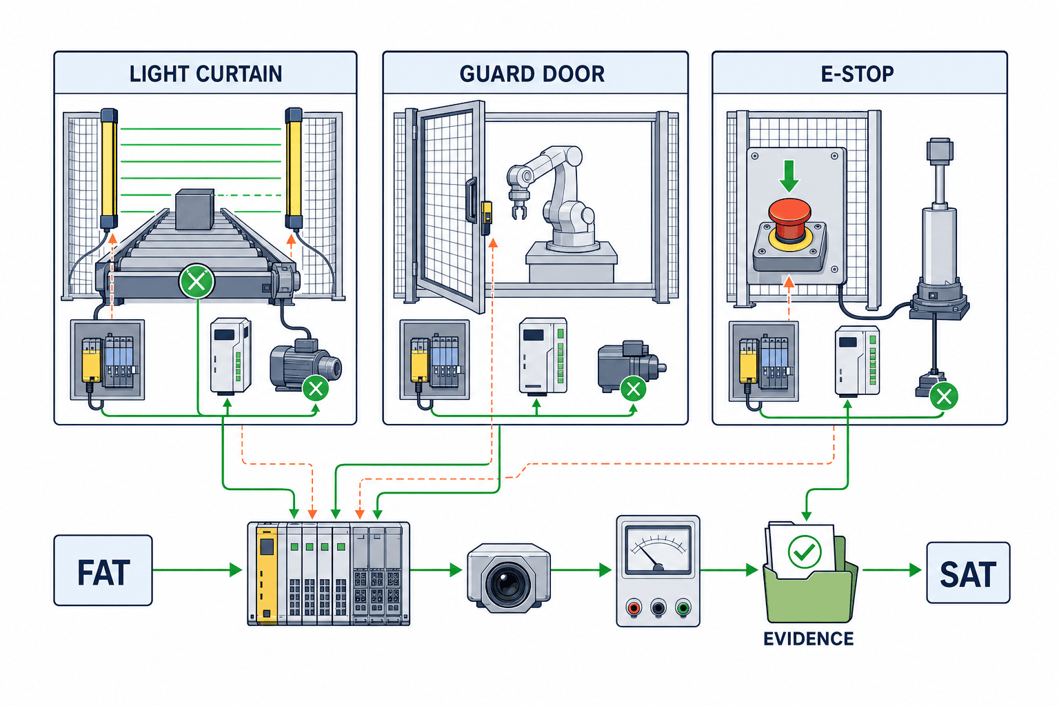
FAT should test more than expected operation. Confirm that the build matches the design baseline, then simulate channel opens, discrepancy, detected shorts where applicable, communication loss, output faults, held E-stops, reset conflict, power cycling and unexpected-restart prevention. Read safety-drive settings back and compare them to the approved list. Anything dependent on site conditions must retain an explicit “not tested” status and a linked SAT case; “FAT passed” must not hide those carryovers.
What SAT must confirm
SAT verifies real wiring, load, speed, inertia, guard distance, lighting, site practice and interaction with upstream/downstream machines. Recheck a light curtain if location, floor reflection, projecting work or a possible bypass path differs from FAT. Confirm not only that an E-stop stops motion, but also the affected zone, retained pressure or gravity, manual reset, release behaviour, display and recovery authority.
Build negative tests into FAT/SAT acceptance
| Device/function | Fault or boundary | Required evidence |
|---|---|---|
| Light curtain | Interruption, channel fault, reset while blocked, closest approach | Output transition, measured stop, restart prevention, event log |
| Guard door | Open, switch discrepancy, locking fault, early unlock demand | Safe state, diagnostics, unlock condition, recovery sequence |
| E-stop | Every device, contact fault, release, multiple simultaneous demands | Stop scope, latching, manual reset, restart prevention |
| Safety drive | Command, communication loss, parameter mismatch | Measured stop, feedback state and approved-setting comparison |
| Safety network | Cable loss, node loss, delay, reconnection | Defined reaction, diagnostic time and recovery condition |
| Power/recovery | Brownout, total loss, CPU replacement, restore | Safe startup, version match and retest record |
Record calibration status, speed, load, software version and environmental conditions. A video is supporting evidence, not a replacement for a test ID, expected result, measured value and accountable approval. A failed case needs a deviation ID, containment, cause, correction, impact analysis, regression test and reapproval.
Keep an evidence ledger from hazard to field result
Maintain this unbroken path:
Hazard ID → risk-reduction measure → safety-function ID → PLr/SIL target → circuit/component → PLC block/parameter → calculation → verification case → FAT/SAT case → result → deviation/correction → approval
| Ledger area | Minimum retained content |
|---|---|
| Requirement | ID, hazard, mode, safe state, response time, target and rationale |
| Design | Drawing, component model, certification, constraint, calculation and software version |
| Implementation | I/O, PLC block, drive setting, HMI and access permission |
| Test | Case ID, precondition, action, expected/actual result, instrument and evidence link |
| Deviation | Severity, containment, cause, correction, impact and retest |
| Handover | Approval, residual risk, training, periodic test and change ownership |
Version labels such as “final2” are not configuration management. Use an approved baseline, checksum, release note, protected backup and restore test. Replacement of a supposedly equivalent CPU, I/O, sensor, contactor or drive requires comparison of certificate scope, diagnostics, response time, firmware and conditions, followed by the necessary regression tests.
Seven common failure patterns
1. Copying PL e or SIL 3 from a product into the machine claim
Product capability is not the achieved performance of the full function. Evaluate sensor, wiring, logic, output, mechanical stop and proof-test interval as one chain.
2. Outsourcing the risk assessment completely
The plant knows real cleaning, jam-clearing and recovery work. Production, maintenance and EHS must combine that knowledge with the supplier’s design expertise.
3. Replacing engineering with a PL/SIL conversion table
The concepts, assumptions and evaluation methods are not identical. Declare the selected method for each function and review interfaces deliberately.
4. Receiving PLC source but not safety-drive settings
If safe speed or stopping functions depend on the drive, its parameter set, permissions, backup, revision and test evidence are part of the safety deliverable.
5. Ending FAT with a normal-operation demonstration
Without open, short, communication-loss, reset and power-recovery cases, the demonstration is not evidence of the required fault reaction. Put negative tests in the contract.
6. Adding remote maintenance as a convenience feature
Who can alter safety code or parameters, from which terminal and during which window is a safety-lifecycle decision. Build approval and audit into the access route.
7. Running only a narrow test after a change
A timer change can affect protective distance. Identify the impacted functions and regression scope before implementation, then approve the updated evidence ledger.
Thailand and ASEAN implementation details
Keep one safety ID across languages
Operational guidance may be Thai, English, Japanese or Vietnamese, but safety-function IDs, I/O tags, drawings and test IDs should remain stable across translations. Separate translated explanations from technical identifiers and verify worker comprehension, not only linguistic correctness.
Manage remote maintenance as an entry point for safety change
For remote OEM support, require plant approval, time limits, personal accounts, screen recording or equivalent logs, pre-work backup, post-work version check and defined retesting. Include a procedure for a lost connection so an unsafe intermediate state is not left behind.
Do not approve an “equivalent” spare by specification alone
For local substitute parts, compare exact certification, operating conditions, diagnostics, response time, terminal arrangement and firmware. A spare-parts list should include permitted versions and post-replacement tests.
Do not separate the control panel from field wiring
A correct panel cannot compensate for common field-cable damage, insufficient protective distance or an easily defeated switch. Contract panel, field devices, mechanical guarding and site validation as one safety-function boundary.
Coordinate controls with physical protection. See our robot safety fence and ISO 10218 guide and PLC program outsourcing guide. For EU-bound machinery, connect the project to our EU Machinery Regulation 2027 guide for Thailand.
Pre-contract Go/No-Go checklist
Proceed from product quotation to contract only when the team can answer all twelve points with evidence:
- Machine, mode, boundary and user scope are defined.
- Hazards and risk-reduction measures are structured using ISO 12100 methodology.
- Every function has an ID, input, logic, output, safe state and response time.
- The PLr or SIL rationale and method are recorded by function.
- Blocks and responsibilities are clear from sensor through actuator.
- Product certificate scope, manual, conditions and constraints were checked.
- PLC code, drive, safety I/O and parameters share change control.
- Remote connection, accounts, logs, backup and restore are designed.
- Verification and validation roles, independence and approval are assigned.
- FAT/SAT include both normal and negative tests.
- An evidence ledger traces requirement ID to final result.
- Periodic tests, replacement, change and revalidation are contracted.
FAQ: safety PLC, PLr, validation and FAT/SAT
What is a safety PLC?
It is a controller designed and assessed to implement safety-related control functions with defined diagnostics, fault reaction, development constraints and conditions. It does not choose the hazard target or prove the whole machine by itself.
Can a PL e product determine the ISO 13849-1 PLr?
No. PLr comes from the application’s risk assessment. Achieved performance also depends on architecture, data, diagnostics, common-cause measures, software and proof testing.
Can SIL and PL be converted directly?
Do not base design on a casual one-to-one conversion. Apply the selected method consistently and document any interface between methods.
Is ISO 13849-2:2012 still current?
At research time it is the current edition and a revision is underway. State the contracted edition and define how later publication will be managed.
What should a safety PLC RFP request first?
Machine scope, risk assessment, SRS and responsibility matrix—before a hardware comparison.
What is the practical difference between FAT and SAT?
FAT verifies the baselined design, panel, code, simulated I/O and fault responses. SAT verifies actual wiring, loads, stopping time, guard geometry, machine interfaces and operating practice.
Does a certified PLC remove the need for validation?
No. Machine validation confirms that the selected, integrated and installed safety functions achieve the intended risk reduction.
Can a safety PLC project finish in 90 days?
The 90-day plan is a bounded example for one machine or representative cell, not a guaranteed plant rollout. Scope, documentation quality, shutdown access and regulatory needs determine duration.
Must every safety function be retested after remote maintenance?
Use a documented impact assessment to set the scope. A change to safety logic, parameters, firmware, shared libraries or communication conditions requires regression tests for affected functions and any necessary revalidation. Even when the session was “view only,” confirm by version and access logs that no unauthorised change occurred.
Conclusion: contract the evidence, not the certificate number
A safety PLC implementation succeeds when hazard, safety function, PLr/SIL target, circuit, software, parameter, verification, validation and FAT/SAT result form one controlled evidence chain. The September 2026 certificate announcement expands component options, but buyers must still distinguish certified equipment from demonstrated machine-level conformity.
TOMAS TECH can help define safety functions, an RFP response matrix, PLC/panel boundaries, FAT/SAT cases and the evidence ledger even before a controller brand is chosen. To discuss a bounded assessment for a Thailand plant or an overseas-OEM project, use our contact page.
References
- Mitsubishi Electric, 17 September 2026 release
- EUR-Lex, Regulation (EU) 2023/1230
- European Commission, Machinery
- ISO 12100:2010
- ISO 13849-1:2023
- ISO 13849-2:2012
- IEC 62061:2021+AMD1:2024+AMD2:2026 CSV, current consolidated edition
- IEC 62061:2021 base publication
- IEC 62061:2021/AMD2:2026
- Mitsubishi Electric, Safety CPU
- Mitsubishi Electric, Safety I/O manual
- IFA/DGUV, Functional safety and SISTEMA report
Note: the 90-day sequence, RFP list, test examples and evidence ledger are TOMAS TECH planning templates, not substitutes for standards or legal advice. A competent team must tailor the design to the machine, operating conditions, destination, customer requirements and contracted editions.


