


Most conversations about robot safety fence standards start with the same sentence from the plant floor. We are buying a collaborative robot, so we will not need a fence. The type of robot is not what decides the answer. What decides it is the performance level assigned to each safety function through risk assessment, the stopping distance calculated under ISO 13855, and the installation taken as a whole, including the end effector and the workpiece. The ISO 10218 revision published in February 2025 wrote all three points into the standard in plain language. This article walks through what changed, works a stopping distance calculation, and lays out a five year cost estimate for three safety methods.
Robot safety fence standards changed in 2025 — what the ISO 10218 revision says
ISO 10218 sits at the centre of industrial robot safety, and revised editions of both Part 1 and Part 2 were published on 18 February 2025. ISO 10218-1:2025 covers the robot itself. ISO 10218-2:2025 covers robot systems and integration. The previous editions dated from 2011, which makes this the first major overhaul in fourteen years.
Look back at what happened on factory floors during those fourteen years and the revision starts to feel inevitable. In 2011, collaborative robots were still the exception. A robot lived inside a fence, and when a person went in, the robot was stopped. That premise formed the skeleton of the standard. What actually happened afterwards was different. Applications built on force and pressure limiting multiplied. Replacing part of a fence with a safety laser scanner became an ordinary configuration rather than an exotic one. The shape of the gripper and the shape of the workpiece turned into the primary cause of incidents in more and more cases. The standard, in other words, had been running behind the reality of the shop floor for some time.
The revision rests on five main pillars.
- Robots are now sorted into two classes.
- Functional safety requirements moved from implicit to explicit.
- Cybersecurity requirements were added.
- Safety guidance on end effectors and on manual load and unload was brought into the body of the standard.
- The subject of the standard moved from the robot system to the robot application.
Of these, the ones that bear directly on the practical question of whether you need a fence are the first, the second and the fifth. We will take them in turn.
Class I and Class II are a new way of sorting robots
The class split is new in the 2025 editions. Class I refers to large, high power industrial robots. Class II refers to the smaller, lower power robots intended for collaborative applications.
This is where a misunderstanding tends to take root, so it is worth nailing down early. This is not a standard that says buying a robot classified as Class II removes the need for a fence. The classification exists to organise the design requirements that the robot itself has to meet. How you actually install that robot, what gripper you bolt onto it, what workpiece you ask it to carry, at what moment a person walks up to it and how close that person gets — everything from that point onward belongs to risk assessment, which we come to below.
If anything, it is more accurate to expect the classification to work in the opposite direction from the one people hope for. Until now the phrase collaborative robot has been used as though it were a product category, and with it spread the impression that picking that product was itself a guarantee of safety. What the classification does is separate, in the text of the standard, the design requirements placed on the robot from the safety that has to be secured on the application side. Reading it as the point at which the robot conversation and the application conversation stopped being mixed together is close to what actually happened.
The blanket PL d requirement is gone, replaced by risk assessment per safety function
This may be the change with the largest practical impact of them all.
The 2011 editions effectively required PL d, performance level d, across the board for the safety related parts of a robot control system. Whatever the safety function happened to be, you designed it to reach PL d. That is easy to communicate, and it can also come out either excessive or insufficient for the actual hazard.
The 2025 editions drop the blanket requirement. In its place, you carry out a risk assessment for each safety function and determine the appropriate PL from that result. PL d and PL e under ISO 13849-1 still appear as typical values, but that is a statement about what the answer often turns out to be, not a statement that it has to be that answer.
Read as an increase in design freedom, this is good news. However, an increase in freedom also means the responsibility for the judgement moves onto our side of the table. Where saying we designed it to PL d used to end the discussion, from now on you need to be able to show why this particular PL was assigned to this particular safety function, together with the risk assessment record that supports it. It is a change that pushes in the direction of documentation quality being what gets examined.
For reference, the representative safety functions expected of a robot include monitored standstill, which was called safety-rated monitored stop before the 2025 revision, safety-rated speed monitoring, and safety-rated axis and space limiting. Because some function names changed, cross-checking terminology is worth doing whenever you reuse an existing design document.
ISO/TS 15066 was absorbed into the body of the standard
In the field of collaborative robot safety, the document people have leaned on for years is ISO/TS 15066. It is a technical specification that sets limit values for contact force and pressure by body region, and it was the single anchor available when designing collaborative work based on force and pressure limiting.
In the 2025 editions, the content of ISO/TS 15066 was absorbed into the body of ISO 10218-2:2025. It moved up from the status of a technical specification, a TS, into the text of an international standard, an IS.
The practical meaning of that promotion lies in how much stronger the obligation to refer to it becomes. A TS was a document you were expected to consult. A requirement written into the body of an IS is a requirement you are expected to meet. If you intend to build a fenceless configuration on force and pressure limiting, there is no longer a way around the work of demonstrating by measurement that the limit values are satisfied. That is exactly why the cost estimate later in this article carries a line item for measurement and recording of contact force and pressure under the fenceless method.
In the same way, content that used to live in separate technical reports, TR 20218-1 on end effectors and TR 20218-2 on manual load and unload, has been consolidated into the body of the standard. Having documents that were scattered pulled together into one place is a straightforwardly welcome change from a designer’s point of view.
Why “a cobot needs no fence” does not hold — how collaborative robot safety actually works
This is the heart of the matter. As set out at the top, whether you need a safety fence is not decided by whether the robot is a collaborative robot. Here are three angles that explain why.
What is safe is not the robot but the robot application
With the 2025 revision, the subject of the standard shifted from robot system to robot application. It looks like a quiet editorial change, and as a shift in the way of thinking it is the most important one in the whole revision.
A robot application takes in not only the robot itself but the end effector, the workpiece being handled, the task program and the surrounding equipment. In other words, what gets evaluated is no longer the question is this robot safe. It is the question is the whole installation safe when this robot handles this workpiece with this gripper through this motion.
That difference has been confirmed painfully on factory floors many times over. A robot that the catalogue says can coexist with people becomes dangerous the moment you fit a sharp tool at the end of the arm. If the workpiece is a 5 kg metal sheet, the edge of that sheet can cut a hand even where the force limits in the standard are satisfied. The robot motion conforming to the standard and the application being safe are two separate propositions.
So the sentence “it is a collaborative robot, therefore no fence is needed” fails at the point where the subject of the sentence is the robot itself. The correct sentence reads more like this. We carried out a risk assessment for this application, and concluded that measures other than a fence bring the risk down to a level we can accept. It is a long sentence, and that length is what the reality actually looks like.
End effectors and workpieces are now inside the scope of evaluation
As described above, guidance on end effectors moved from a technical report into the body of the standard. That puts the gripper and the workpiece squarely at the front of the risk assessment rather than off to one side of it.
Concretely, these are the kinds of points that turn into problems.
- Sharp features. The tips of gripper fingers, the cut face of a workpiece, burrs. Even with force limiting active, a small contact area sends the pressure shooting up. That is precisely why the limit values derived from ISO/TS 15066 specify pressure as well as force.
- Pinching. The opening and closing motion of the gripper, the gap between the workpiece and the robot body, the gap between the workpiece and a surrounding structure. Even at low robot speed, a trapped finger can mean a serious injury.
- Loss of hold. A vacuum pad losing suction, a chuck loosening. The robot itself may stop, but a dropped workpiece does not.
- Workpiece changes. Even if today’s workpiece passed the force and pressure measurements, switching to a different workpiece next month means those measurement results are no longer the evidence for anything.
That last item is the one that bites hardest on cost. A fenceless configuration does not only take effort in initial design and measurement. It generates a fresh round of measurement every time the workpiece changes. The more the plant runs high-mix low-volume production, the higher the frequency of that re-measurement climbs. That structure is the reason the fenceless method shows the highest maintenance and re-verification cost in the estimate further down this article.
On the wider question of whether to bring in a collaborative robot at all, we have set out a broader view in our guide to deciding on collaborative robot implementation.
Teaching is the moment of greatest exposure
There is one more argument that tends to get overlooked. Discussion concentrates on the risk during automatic operation, and the risk during teaching gets pushed to the back of the queue.
It is obvious once you stop and think about it. Teaching is work carried out with a person inside the robot’s range of motion, while the robot is moving. In a cell where automatic operation is isolated behind a fence, teaching still puts the person and the robot in the same space. Without reaching for statistics, the fact that this is the most dangerous state should line up with what anyone who has stood next to a cell already feels.
The 2025 editions explicitly organise the safety functions that address this phase, namely safety-rated speed monitoring, axis and space limiting, and the handling of enabling devices. Speed limits during teaching and requirements on the enabling switch of a teach pendant existed before as well, but the shift from those requirements being implicit to being explicit is not a small thing.
Two practical implications follow. First, teaching-time safety measures are needed whether or not there is a fence. Choosing a fenceless configuration does not make the teaching risk disappear. Second, on a line where teaching is frequent, investment in offline teaching or direct teach that reduces the time a person spends inside the cell at all can be more effective than investment in safety devices, depending on the case.
Stopping distance is what decides the fence — a worked ISO 13855 example
So far the discussion has been conceptual. What actually decides whether you need a fence and where it goes is a far more concrete number. It is the stopping distance.
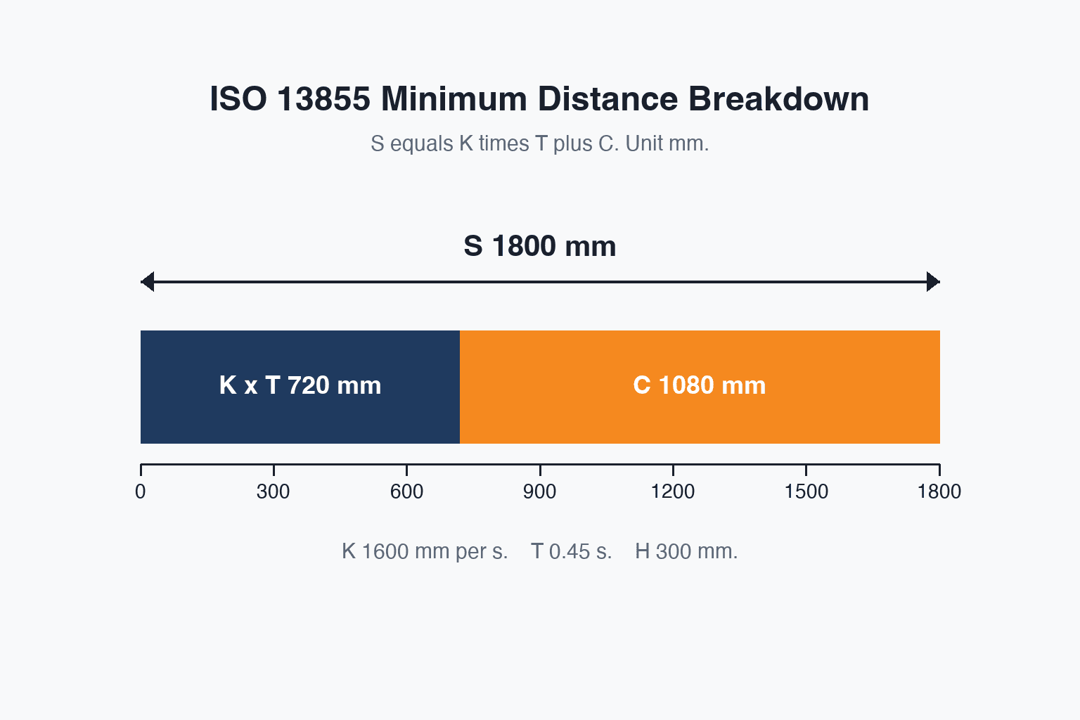
Inside S = K × T + C
ISO 13855 defines the minimum distance S that has to be kept between a detection device and the hazard with the following formula.
S = K × T + C
Each term means the following.
- K is the approach speed of the human body in mm/s. Where you assume a whole body walking approach, 1,600 mm/s is used. Where you assume a hand or an arm reaching in, 2,000 mm/s is used.
- T is the total response time in seconds. It is the sum of the response time of the detection device, the response time of the safety control equipment, and the time it actually takes the machine to come to a stop. Settling for the catalogue figure of the detection device alone is an extremely common error here, and T is the total for the whole chain.
- C is the intrusion distance correction in mm. The formula changes with the orientation in which the detection field is installed. For a horizontally mounted detection field, C = 1200 − 0.4H, where H is the height of the detection field above the floor in mm, and this value is not allowed to fall below 850 mm. For a vertically mounted light curtain, C = 8(d − 14) is used, where d is the resolution in mm.
Let us run the numbers for a case where a safety laser scanner replaces part of a fixed fence.
Assumptions
- Approach speed K = 1,600 mm/s, a walking approach
- Scanner response time = 0.08 seconds
- Safety controller response time = 0.02 seconds
- Robot stopping time = 0.35 seconds
- Height of the horizontal detection field H = 300 mm
Calculation
T = 0.08 + 0.02 + 0.35 = 0.45 seconds
K × T = 1,600 × 0.45 = 720 mm
C = 1200 − 0.4 × 300 = 1200 − 120 = 1,080 mm, which is above the 850 mm floor, so this value is taken as it stands
S = 720 + 1,080 = 1,800 mm
In other words, you need 1.8 m of space between the detection boundary of the scanner and the outer edge of the robot’s range of motion.
What happens in a plant that cannot free up 1.8 m
The first time this figure of 1,800 mm goes up on the screen, the mood in the room usually changes. People had been expecting that dropping the fence would save floor space, and the result says the opposite, that it takes more space than a fence would.
With a fixed fence, the clearance between the fence and the range of motion can sometimes be satisfied with the few hundred millimetres you keep for pinch prevention. Replace it with a scanner and you have to secure 1.8 m, because the assumption is now that a person is walking towards the hazard. Having removed the physical obstacle, you are left buying the same protection back in time. What this means is that the intuition that removing a fence saves space frequently turns out to be inverted.
So what do you do when there is not enough floor area? Go back to the formula and the answer is plain. C is a geometric value fixed by the height of the detection field, so it does not move very far. What can move is T. And within T, the largest term is the robot stopping time.
Suppose that in the example above we manage to bring the robot stopping time down from 0.35 seconds to 0.15 seconds.
T = 0.08 + 0.02 + 0.15 = 0.25 seconds
K × T = 1,600 × 0.25 = 400 mm
S = 400 + 1,080 = 1,480 mm
The 1,800 mm becomes 1,480 mm, a reduction of 320 mm. No amount of arguing about whether to have a fence produces those 320 mm. What produces them is stopping performance.
There is more than one way to shorten stopping time. Improving brake response, revisiting deceleration parameters, lowering the robot motion speed itself, choosing the stop category. Each of these belongs in the safety design discussion, and each of them also calls for confirming the stopping time by measurement, that is, a stopping performance measurement. Robot stopping time is not a catalogue figure, because it varies with posture, payload and speed.
How far you keep this kind of work in house and where you hand it to a partner is a question where the framing in our article on choosing a robot system integrator is a useful reference. Whether an integrator has the setup to carry out stopping performance measurement is one of the practical dividing lines when you evaluate them.
Breaking down the five year total for three methods — our estimate
Choosing a safety measure is a safety discussion and a cost discussion at the same time. Here we have estimated the five year total for three methods. Everything below is our own estimate, and actual amounts move with specification, supplier and exchange rate. Please read it as a framework for thinking rather than as a price list.
Assumptions
- A Japanese-affiliated factory in Thailand, one cell with a single articulated robot in the 20 kg payload class
- 250 operating days per year, evaluated over 5 years
- People enter the cell 8 times a day, 4 changeovers plus 4 for workpiece replenishment and clearing jams. Over five years that is 8 × 250 × 5 = 10,000 entries
- Opportunity loss assumed at 1,200 baht per hour of cell downtime
The three methods
- Method A is a fixed safety fence with an interlocked door.
- Method B is a partial fence with a safety laser scanner.
- Method C is a fenceless configuration using force and pressure limiting on a collaborative robot.
The initial cost ranking flips over five years
Start with initial cost.
| Item | A Fixed fence | B Partial fence and scanner | C No fence |
|---|---|---|---|
| Difference in robot and base frame | 0 | 0 | 250,000 |
| Physical fence and door | 180,000 | 90,000 | 0 |
| Safety devices | 95,000 | 310,000 | 60,000 |
| Measures for sharp features and pinch points on tools and workpieces | 20,000 | 20,000 | 150,000 |
| Risk assessment, design and validation | 220,000 | 340,000 | 260,000 |
| Measurement and recording of contact force and pressure | 0 | 0 | 180,000 |
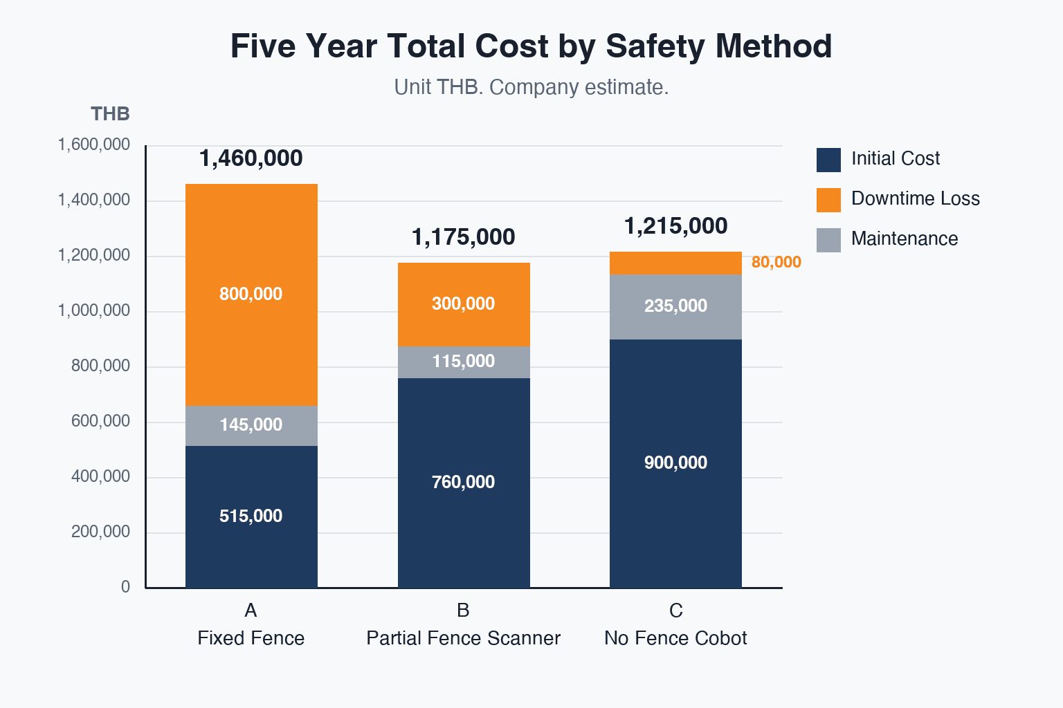
| Initial total | 515,000 | 760,000 | 900,000 |
Unit: THB
On initial cost alone the ranking is A at 515,000, then B at 760,000, then C at 900,000. The fence is cheapest and the fenceless option is the most expensive. If this table is the only one that reaches the approval meeting, Method A gets picked.
What that table leaves out is operational loss. Every time a person enters the cell, the cell stops. And how long it stops for differs enormously by method.
With the fixed fence and interlocked door of Method A, you stop the robot to open the door, then after the work you carry out a safety check, reset, run a return to home position and restart. That whole sequence averages 4.0 minutes. With the partial fence and scanner of Method B, the robot decelerates in the warning field and stops in the protective field, and once the person is clear it can resume with a reset action, which we put at an average of 1.5 minutes. With the fenceless Method C, the robot slows as a person comes closer and recovers as they move away, which we put at an average of 0.4 minutes.
| Item | A | B | C |
|---|---|---|---|
| Average downtime per entry | 4.0 min | 1.5 min | 0.4 min |
| Annual downtime | 133.3 hours | 50.0 hours | 13.3 hours |
| Annual opportunity loss | 160,000 | 60,000 | 16,000 |
| Five year operational loss | 800,000 | 300,000 | 80,000 |
Annual downtime is calculated as 8 entries × 250 days × minutes ÷ 60. Method A works out at 133.3 hours a year, which means more than 666 hours disappear into cell downtime over five years.
Next, maintenance and re-verification cost over the same five years.
| Item | A | B | C |
|---|---|---|---|
| Breakdown | Refencing for 2 layout changes 120,000 plus inspection 25,000 | Annual verification 75,000 plus 2 reconfigurations 40,000 | 3 re-measurements of force and pressure after workpiece changes 210,000 plus inspection 25,000 |
| Five year maintenance and re-verification | 145,000 | 115,000 | 235,000 |
The maintenance cost of Method C stands out because, as described earlier, the force and pressure measurement has to be redone every time the workpiece changes. A fenceless configuration is not a build it and forget it method, and that is worth understanding before you commit to it.
Adding the three blocks together gives the following.
| Category | A Fixed fence | B Partial fence and scanner | C No fence |
|---|---|---|---|
| Initial cost | 515,000 | 760,000 | 900,000 |
| Five year operational loss | 800,000 | 300,000 | 80,000 |
| Five year maintenance and re-verification | 145,000 | 115,000 | 235,000 |
| Five year total | 1,460,000 | 1,175,000 | 1,215,000 |
The ranking has swapped around. Where initial cost gave A < B < C, the five year total gives B < C < A. The method that looked cheapest, Method A, ends up the most expensive, and the gap between A and B opens to 285,000 baht. The gap between Method B and Method C is 40,000 baht, so under these assumptions B has a slight edge.
Save the 245,000 baht difference in initial cost by choosing Method A, and you pay 285,000 baht more over five years. This is the classic shape of what happens when the return on a robot investment gets judged on initial cost alone.
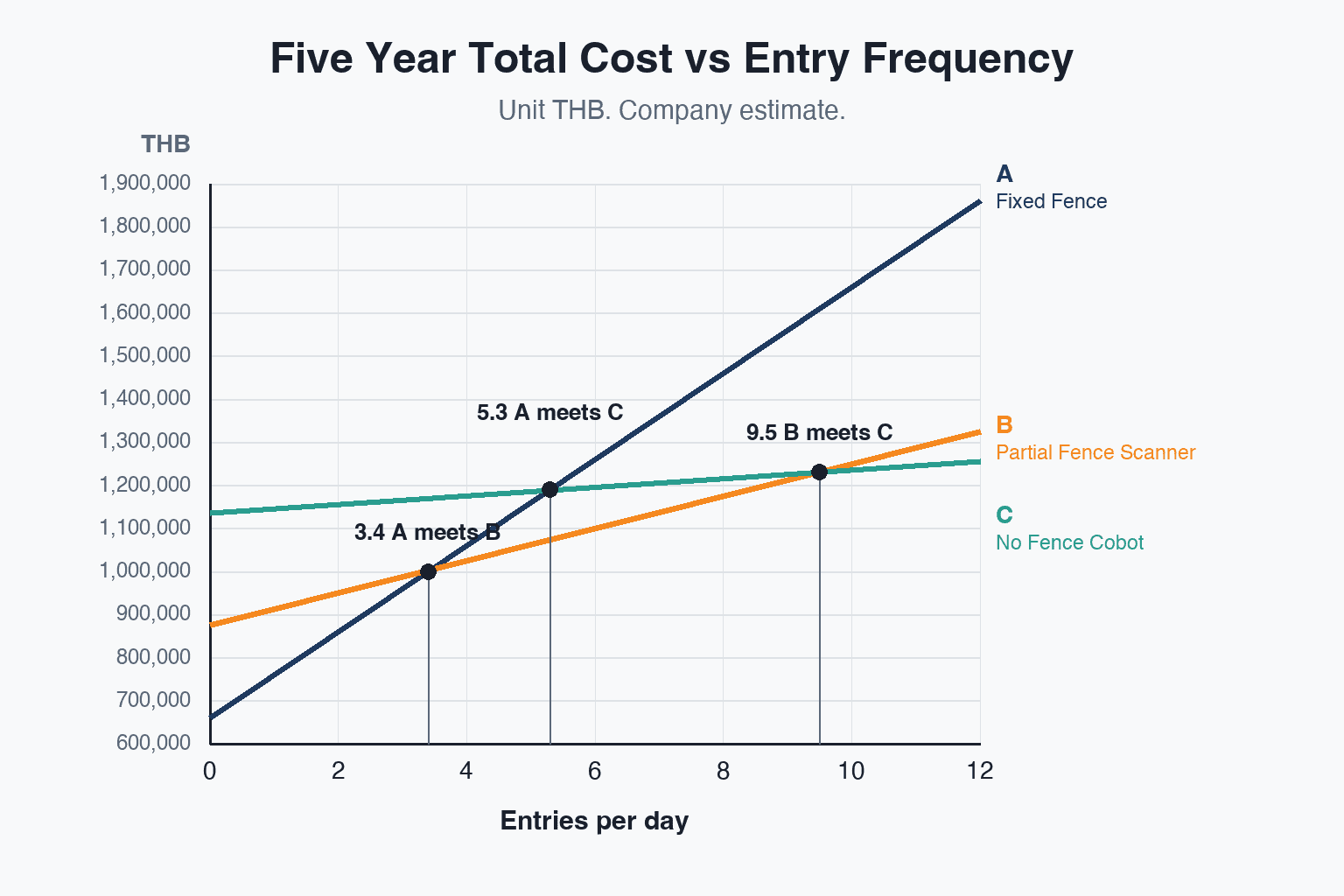
The break-even point is 3.4 entries per day
That conclusion, however, stands on the assumption of 8 entries per day. Change the assumption and the conclusion changes with it, so it is worth pinning down algebraically where the lines cross.
Method A against Method B
The difference in initial cost is 760,000 − 515,000 = 245,000 baht, with B on the expensive side. The difference in maintenance and re-verification is 115,000 − 145,000 = −30,000 baht, with B on the cheaper side. Together, the effective gap that does not depend on entry frequency is 215,000 baht, with B on the expensive side.
The difference in downtime per entry is 4.0 − 1.5 = 2.5 minutes. Converted into money that is 2.5 × 1,200 ÷ 60 = 50 baht.
So 215,000 ÷ 50 = 4,300 entries is where B catches up with A. Divided by the 1,250 operating days in five years, that is roughly 3.4 entries per day.
Which means that once people enter the cell more than 3.4 times a day, Method B is cheaper than Method A on a five year total. And 3.4 times a day is not a demanding number at all. Two changeovers a day plus two jam clearances a day is already past it.
Method A against Method C
The effective gap is 385,000 baht in initial cost plus 90,000 baht in maintenance, giving 475,000 baht with C on the expensive side. The difference per entry is 4.0 − 0.4 = 3.6 minutes, which is 72 baht.
475,000 ÷ 72 is approximately 6,597 entries, or roughly 5.3 entries per day.
Method B against Method C
The effective gap is 140,000 baht in initial cost plus 120,000 baht in maintenance, giving 260,000 baht with C on the expensive side. The difference per entry is 1.5 − 0.4 = 1.1 minutes, which is 22 baht.
260,000 ÷ 22 is approximately 11,818 entries, or roughly 9.5 entries per day.
This is the point that matters most. For Method C to come in under Method B, entries have to exceed 9.5 per day. At the 8 entries per day we assumed here, Method B is 40,000 baht cheaper. A fenceless configuration comes out as the right answer on cost only in applications with a genuinely heavy flow of people in and out, an assembly process where a person and a robot take turns touching the same workpiece being the obvious example.
Turn that around and, on a line with fewer than 3.4 entries a day, say large-lot production where changeover happens a few times a week, simply choosing a fixed fence comes out cheapest. A fence is not an outdated method. Where people rarely go in and out, it remains the best option available.
There is one practical conclusion to draw from this estimate. Before you settle on a method, count how many times a day someone enters that cell. It is a number that does not appear anywhere in the equipment specification, and it is the number that decides the five year total. On an existing line a week of observation is enough. On a new line it can be estimated from the process design.
For method selection on assembly processes where people are involved frequently, we have set out the view from the process side in our article on configuration patterns for assembly automation robots.
Additional requirements for factories in Thailand — Ministerial Regulation B.E. 2564 and penalties
Everything above concerns international standards. When you push automation forward in Thailand, local legal requirements land on top of them.
Preventing contact with dangerous parts of machinery is the floor
In Thailand, the Ministerial Regulation on occupational safety and health for machinery, cranes and boilers, B.E. 2564, that is 2021, was published in the Government Gazette on 6 August 2021. The regulation requires guarding to be installed to prevent people from coming into contact with the dangerous parts of machinery.
The relationship between standards and law gets muddled easily, so it is worth separating. ISO 10218 is an international standard and does not in itself carry legal force inside Thailand. Ministerial Regulation B.E. 2564 is Thai law. Formally, then, conformity with a standard and compliance with the law are two different things.
In practice, though, there is almost no value in keeping them apart. On what technical basis will you explain that you have satisfied the regulation’s requirement to prevent contact with dangerous parts? The body of work available for that explanation is ISO 10218 and ISO 13855. The risk assessment record, the stopping distance calculation, the PL evaluation of each safety function. With those in hand, the explanation that you meet the legal requirement stands up at the same time. Conversely, if you put up a fence without any standard-based study behind it, you have no basis on which to explain why the fence is in that particular position.
The penalties are worth checking too. Under the Occupational Safety, Health and Environment Act B.E. 2554, that is 2011, a violation carries imprisonment of up to one year, a fine of up to 400,000 baht, or both. Set against the amounts in the estimate above, the fine on its own is not decisively large. But given that imprisonment is on the list, and given that where an accident actually happens the shutdown of operations and the damage to trust arrive well before any penalty does, we do not consider this the kind of item that belongs on a cost comparison at all.
Safety measures are chosen on cost effectiveness, but that means choosing among several options that already satisfy the requirement of bringing risk down to an acceptable level. An option that fails that requirement is not on the list no matter how cheap it is. The three methods above are compared on the premise that each of them has been through a risk assessment and reaches an acceptable level.
If you export to Europe, keep January 2027 and the EU Machinery Regulation in view
If products or equipment made in your plant in Thailand go to Europe, there is another development worth keeping in view.
The first item is the EN harmonisation of ISO 10218:2025, meaning its status as a European harmonised standard. A transition period of 24 months has been applied for, but whether it will be cited in the Official Journal of the EU is undecided at this point. If it is listed as a harmonised standard, conforming to it produces a presumption of conformity with the Machinery Directive and the Machinery Regulation. On projects that involve export, the listing status is something to keep checking as it develops.
The second item is the cybersecurity requirements added in the 2025 revision. These are described as written with the EU Machinery Regulation that applies from January 2027 in mind. Robot safety used to mean mechanical hazards and the guarding that keeps people away from them. Now risks such as unauthorised access to a network-connected robot, or interference with its safety functions, are stated explicitly as requirements in the standard.
For people on the factory IT side, this may be the change that lands hardest in day to day work. How to segment the network of a robot cell, how to design access control on the robot controller, how to manage the path by which firmware gets updated. Topics that never used to earn an invitation to the safety design meeting are now arriving as requirements in the standard. We would suggest working on the OT network design in parallel from the early stages of an industrial robot installation rather than after the fact.
As background on the wider market, IFR World Robotics 2025 reports that new installations of industrial robots worldwide reached 542,000 units in 2024, with an operational stock of 4,664,000 units. By region, the share of new installations was 74 percent in Asia, 16 percent in Europe and 9 percent in the Americas. For 2025, 575,000 units are expected. With installations concentrated in Asia to that degree, plants in Thailand can expect to face revisions of international standards more often, not less, in the years ahead.
Five things to settle before an industrial robot installation
Here is the material above turned into a checklist to work through before installation.
1. Count how many times a day someone enters that cell.
As the estimate showed, this number decides the five year total. A week of observation on an existing line, or an estimate from the process design on a new one, is enough. Counting it split by purpose, changeover, workpiece replenishment, jam clearing, cleaning, inspection, teaching, also shows you where the room for improvement sits later on.
2. Establish the robot stopping time by measurement.
Of the terms in T that the ISO 13855 calculation needs, the dominant one is the robot stopping time. And because it varies with posture, payload and speed, a catalogue figure does not cover it. For the robot you plan to install, put a stopping performance measurement under the actual operating conditions into the project plan. The tighter the floor space constraint on a project, the more that measurement is worth.
3. Fix the specification of the end effector and the workpiece, including how likely they are to change.
If you are considering a fenceless configuration, force and pressure measurement is required. And the measurement is required per combination of gripper and workpiece. How much do you expect the workpieces to change over the next three years? That outlook has a large effect on the maintenance cost of Method C. If a move towards higher product variety is on the cards, that should be built into the comparison table from the start.
4. Determine the PL required for each safety function and keep the reasoning on record.
Now that the blanket PL d requirement has been dropped in the 2025 editions, the responsibility for explaining why this PL sits on our side. The risk assessment record, the PL selected, and the equipment configuration that achieves it. Unless that set of three is documented from the design stage onward, rework tends to show up later at validation or audit.
5. Decide the work procedures for teaching and maintenance at the same time as the equipment specification.
Robot teaching and maintenance work are the moments when a person gets closest to the robot. Despite that, they are also an area that often gets bolted on after the equipment specification is frozen, in the form of “we will cover it in the operating procedure”. Where the enabling device sits, what speed limit applies during teaching, what mutual confirmation procedure applies when more than one person is working. These belong on the table at the same time as the equipment design.
Frequently asked questions
Which robot safety fence standards should I be looking at?
The core documents are ISO 10218-1:2025, covering the robot itself, and ISO 10218-2:2025, covering robot systems and integration. Both were published on 18 February 2025. Alongside them you refer to ISO 13855 for safety distance calculation and ISO 13849-1 for the performance level of safety related control systems.
Note also that the limit values for contact force and pressure on the human body, previously specified in ISO/TS 15066, have been absorbed into the body of ISO 10218-2:2025. In the same way, the content of the technical reports on end effectors and manual load and unload, TR 20218-1 and TR 20218-2, has been consolidated into the body of the standard. Having fewer documents to chase is a welcome practical change.
Does a collaborative robot need a safety fence?
The accurate answer is that sometimes it does and sometimes it does not. What decides it is not whether the robot is a collaborative robot but the outcome of the risk assessment.
Three things mainly feed that decision. First, whether contact force and pressure stay within the limit values across the application as a whole, including the end effector and the workpiece. If you handle sharp workpieces or heavy items, a fence or some other measure is needed even where the robot itself supports force limiting. Second, whether the stopping distance calculated under ISO 13855 can be accommodated. Third, whether the risk is at an acceptable level across every operating mode, teaching and maintenance included.
The one judgement that runs directly against the thinking in the standard is “we bought a collaborative robot, so no fence is needed”.
How much does a robot safety fence cost?
In the estimate in this article, for one cell with a robot in the 20 kg payload class in Thailand, the cost of the physical fence and door itself is put at 180,000 baht in the fixed fence configuration and 90,000 baht in the partial fence configuration. Comparing fence prices in isolation has little meaning, though. You need to look at the total including safety devices, risk assessment, operational loss and maintenance.
In the same estimate, the five year total came to 1,460,000 baht for the fixed fence with interlocked door, 1,175,000 baht for the partial fence with safety laser scanner, and 1,215,000 baht for the fenceless force and pressure limiting configuration. That reverses the initial cost ranking. Once entry frequency passes 3.4 times a day the partial fence with scanner becomes cheaper than the fixed fence, and only beyond 9.5 times a day does the fenceless configuration come in under the partial fence with scanner. All of these are our own estimates and shift with specification and conditions.
By when do we need to comply with the 2025 editions of ISO 10218?
There is no single global deadline that applies to everyone. The standard itself was published on 18 February 2025.
For Europe, a transition period of 24 months has been applied for in relation to its status as an EN harmonised standard, but whether it will be cited in the Official Journal of the EU is undecided at this point. On projects aimed at Europe, then, the listing status needs to be checked as it develops. In addition, since the 2025 editions include cybersecurity requirements written with the EU Machinery Regulation applying from January 2027 in mind, that timing serves as the effective marker for equipment destined for Europe.
For operations inside Thailand alone, there is no direct statutory deadline. That said, for equipment being designed from scratch, we see little reason to align with the superseded editions. The way PLs are determined and the shift to treating the whole application as the object of evaluation are in particular the parts where reusing an old design document leaves you with something that does not add up later. Designing to the 2025 editions from the next new project onward is the realistic way to proceed.
Summary
Here are the key points of this article on robot safety fence standards.
The standards changed in 2025. ISO 10218-1:2025 and ISO 10218-2:2025 were published on 18 February 2025, the first major overhaul since the 2011 editions. The pillars are the Class I and Class II classification of robots, functional safety requirements made explicit, the addition of cybersecurity requirements, the integration of guidance on end effectors and manual load and unload, and the change of subject to the robot application. The force and pressure limit values from ISO/TS 15066 were absorbed into the body of ISO 10218-2:2025.
Whether you need a fence is not decided by whether the robot is a collaborative robot. The blanket PL d requirement has been dropped in favour of determining the appropriate PL for each safety function from a risk assessment. What gets evaluated is not the robot itself but the whole robot application, including the end effector, the workpiece and the task program.
Stopping distance is what decides both the need and the layout. Put K = 1,600 mm/s, T = 0.45 seconds and H = 300 mm into S = K × T + C from ISO 13855 and you get K × T = 720 mm, C = 1,080 mm and S = 1,800 mm. Removing a fence does not necessarily save space. Cut the robot stopping time from 0.35 seconds to 0.15 seconds and S becomes 1,480 mm, a reduction of 320 mm. When floor area is short, what helps is stopping performance, not the presence or absence of a fence.
Look at cost over five years and the ranking swaps. In our estimate, initial cost ran A, fixed fence, at 515,000, B, partial fence with scanner, at 760,000 and C, fenceless, at 900,000 baht, in the order A < B < C. The five year total reverses that to B at 1,175,000, then C at 1,215,000, then A at 1,460,000, and the gap between A and B comes to 285,000 baht. The break-even is entry frequency. At 3.4 entries a day B goes below A, at 5.3 C goes below A, and at 9.5 C goes below B. Before settling on a method, count how many times a day someone enters that cell.
In Thailand, Ministerial Regulation B.E. 2564 sits on top of all this. It requires prevention of contact with the dangerous parts of machinery, and the penalty under the Occupational Safety, Health and Environment Act B.E. 2554 is imprisonment of up to one year, a fine of up to 400,000 baht, or both. If you export to Europe, the EU Machinery Regulation applying from January 2027 also belongs in your field of view.
TOMAS TECH supports the factory IT and FA domain for manufacturers from our base in Bangkok. On robot safety design as well, you are welcome to come to us at the stage before model selection, with the questions that have not yet turned into a specification document. How many times a day does a person enter that cell, does the stopping distance fit the floor area you have, and which of fence, partial fence or fenceless suits your own conditions. If you have a layout drawing of the existing line and the work procedures, we can go as far as putting rough numbers against each method with you, so even if you are still at the evaluation stage, feel free to get in touch through our contact page.
Sources
- ISO, ISO 10218-1:2025 Robotics — Safety requirements — Part 1: Industrial robots — https://www.iso.org/standard/73933.html
- ISO, ISO 10218-2:2025 Robotics — Safety requirements — Part 2: Industrial robot applications and robot cells — https://www.iso.org/standard/73934.html
- The Robot Report, ISO 10218 industrial robot safety standard receives major overhaul — https://www.therobotreport.com/iso-10218-industrial-robot-safety-standard-receives-major-overhaul/
- SICK, More safety for humans and machines: the revised ISO 10218 — https://www.sick.com/us/en/more-safety-for-humans-and-machines/w/blog-robotic-norm-iso10218
- InMotion, Collaborative robot safety standards — https://www.inmotion.global/resources/cobot-safety/collaborative-robot-safety-standards/
- IBF Solutions, New standards for industrial robots EN ISO 10218-1 and -2 — https://www.ibf-solutions.com/en/seminars-and-news/news/new-standards-for-industrial-robots-en-iso-10218-1-and-2
- IFR, Global robot demand in factories doubles over 10 years, World Robotics 2025 — https://ifr.org/ifr-press-releases/news/global-robot-demand-in-factories-doubles-over-10-years
- Enviliance ASIA, Thailand Ministerial Regulation on machinery, cranes and boilers B.E. 2564 — https://enviliance.com/regions/southeast-asia/th/report_4310
- TOSH, Occupational Safety, Health and Environment Act B.E. 2554 — https://www.tosh.or.th/TOSH-EN/images/file/osh-act.pdf
- Keyence, Safety knowledge, calculating safety distances — https://www.keyence.com/ss/products/safetyknowledge/caution/
- Schmersal, Calculating safety distances — https://www.schmersalusa.com/press/technical-articles/calculating-safety-distances


