


Introduction: Cable Carrier Selection Should Not Start from the Catalog Size Table
The cables on the moving section of a gantry loader break within a few months, and the line stops every time they are replaced. Requests to review cable carrier selection (or cable chain selection, as it is also called) sometimes start from problems like this. The cables twist into a spiral (a corkscrew) and stick out from the side of the carrier. Everything was left to the machine builder, and there is no drawing showing how many cables, and which ones, run inside. Chips and coolant get into the carrier and clog it. The carrier cracked, so the same size was bought again, and after a while it broke again.
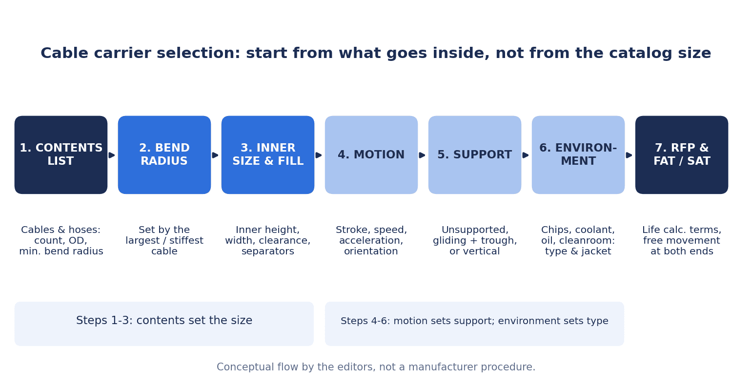
Here is the main argument of this article up front. In this article, we take the view that cable carrier selection is decided by the following three things, before you pick an inner height and inner width from a catalog.
- (1) The list of cables and hoses that run inside: number, outer diameter, minimum bend radius, type
- (2) Motion conditions: stroke, speed, acceleration, mounting orientation, and whether the carrier can reach unsupported
- (3) Environment: chips, coolant, oil, spatter, cleanliness level
(1) and (2) decide the size (inner height, inner width, bend radius) and the support method (unsupported, gliding with a guide trough, vertical). (3) decides the carrier type (open or enclosed, plastic or steel) and the cable jacket material. In addition, the typical causes of cable breakage named by carrier makers and cable makers are concentrated on the cable side, in selection and installation: cables not designed for continuous flexing, overfilling, insufficient bend radius, cables laid while twisted, and tying cables in the moving section. For this reason, we consider in this article that the problem can recur even if only the carrier is bought again. At acceptance, we recommend confirming that the cables in the bend move freely at both ends of the stroke, that the cables run in the neutral zone, how they are fixed, and a re-inspection after initial operation, and keeping the assumptions of the service life calculation in writing.
This article is not a recommendation or ranking of specific products. Figures and product functions are based on each company’s published materials and are presented in the form “the company explains that…”. The cost estimate in the second half uses hypothetical figures prepared for this article.
Why Thai Factories Should Review Moving-Section Wiring Now
Investment in automation continues in Thailand. According to the Thailand Board of Investment (BOI), investment promotion applications for January to June 2026 totaled 1,299 projects worth USD 43.6 billion (about THB 1.47 trillion), up 37% year on year. Of these, the machinery, automation and robotics sector accounted for 82 projects worth USD 387.4 million (about THB 13.1 billion), and the automotive sector for 122 projects worth USD 759.2 million (about THB 25.7 billion). Applications under the “Smart and Sustainable Industry” measure, which covers machinery upgrades, digitalization, and the introduction of automation and robots, were 132 projects worth USD 507.6 million (about THB 17.2 billion). Applications from Japan were 123 projects worth USD 970.1 million (about THB 32.8 billion). All of these are application-based figures and are separate from approval-based figures.
Figures on the production side are mixed. Checking the Federation of Thai Industries (FTI) announcement through the aggregator site Trading Economics (secondary information), car production in August 2026 was 124,646 units, up 10.93% year on year, and domestic sales in August were 59,808 units, up 25.59%. On the other hand, exports in August were down 2.04% year on year, and the FTI forecasts full-year 2026 production to fall 3.33% from the previous year. According to a Reuters report (published by The Star), the Manufacturing Production Index (MPI) for August 2026 rose 4.44% year on year. Note that the Ministry of Industry has revised how the MPI is calculated, adding new electronic products and changing the weights.
These are figures for Thailand as a whole and do not directly describe the situation of any individual factory. Still, at a time when new machines are being introduced and existing equipment modified, linear axes such as gantries, loaders, travel axes and stockers are likely to increase. In this article, we consider that there is real value in deciding the wiring of those moving sections with one consistent approach, rather than leaving it to how each machine happens to be built.
What Is a Cable Carrier: Names and Types
A cable carrier is a component that holds cables and hoses along the moving section of a machine and moves them together with it while keeping a fixed bend radius. It goes by several names. The Japanese name “ケーブルベア” is a registered trademark of Tsubakimoto Chain Co. and is the name of that company’s products. It is also called a “cable chain” or a “cable protection duct”, and igus calls its own products “energy chains (e-chain)”. This article uses “cable carrier” as the generic term and uses the trademark ケーブルベア only when referring to Tsubakimoto Chain products. In Thai, the MISUMI Thailand site uses the name “รางกระดูกงู”.
Types are easier to sort out when you look at them by material, shape and support method.
| Classification | Main types | Points to consider when choosing |
|---|---|---|
| Material | Plastic, steel | Load, length, environment (heat, chips) |
| Shape | Open (crossbars only), with covers, enclosed | How easily chips, spatter and coolant get in |
| Support method | Unsupported, gliding (guide trough), vertical (hanging, standing), side-mounted | Stroke, speed, acceleration, mounting orientation |
As an example of the enclosed type, TSUBAKI KABELSCHLEPP introduces its TKA series for machine tools as “Chip-tight right to the end” and lists the protection class as “Tight (IP54*)”. However, the company writes that this note refers to TKA55 series units with an inner width (Bi) of 50 to 175. It is safer not to read it as meaning IP54 applies to the whole series.
Rolling carriers and carriers dedicated to rotary motion are not covered in this article.
Robot Arm Wiring Is Covered in a Separate Article
Wiring routed along the arm of an articulated robot (a dress pack) faces different requirements from a cable carrier on a linear axis. The KabelSchlepp America technical handbook distinguishes between types of flexing. “Torsional Flex”, which twists 90 to 360° around the center axis, is the motion that typically occurs on multi-axis robots. Inside a cable carrier, on the other hand, the company explains that the motion is “Continuous Flex”, rolling back and forth in a straight line. LAPP also specifies, in the specifications of ÖLFLEX CHAIN 809, torsion conditions (±150°/m) and cycle counts separately from the number of bending cycles. In other words, the main load on a linear axis is “bending”, while on a robot arm it is “torsion and bending”. Robot arm wiring is covered in Choosing a Robot Dress Pack in Thailand: Cable Routing, RFP and FAT/SAT Guide for 2026. This article focuses on linear axes.
What to Decide First: The List of Cables and Hoses Inside
The procedure for working backward from the contents to the cable carrier size is shown in materials from KabelSchlepp America and MISUMI. The KabelSchlepp America handbook defines Step 1 of selection as “calculating the clearance required for the cables and hoses inside the carrier”. The company explains that you add the clearance to the outer diameter of each cable and hose, derive the required inner height from the maximum value, and derive the required inner width from the total plus the thickness of the separators. MISUMI also shows a procedure for its economy series cable carriers in which you select according to what is being wired and decide the inner height from the cable outer diameters.
For that reason, we recommend making a list of what runs inside before opening a catalog. Here is an example of the columns.
| Column | What to enter | What it is used for |
|---|---|---|
| Purpose | Power, motor, encoder, sensor, communication, pneumatic, media | Deciding whether to separate with separators |
| Type | Electrical cable, pneumatic hose, hydraulic hose, media hose | Clearance and fixing method differ |
| Quantity | Including spares | Inner width and future additions |
| Outer diameter | Measured or manufacturer value (mm) | Inner height, inner width, fill |
| Minimum bend radius (moving) | Cable maker’s dynamic, continuous-flex value | Carrier bend radius |
| Weight | kg/m | Layout, unsupported length, support method |
| Jacket material | PVC, PUR, TPE, rubber, etc. | Suitability for the environment, cables sticking to each other |
| Manufacturer part number | Confirming whether it is for continuous flexing | Ordering replacement parts |
| Fixed-end and moving-end positions | Terminals and connections on the panel side and machine side | Fixing method, extra length |
This list is also useful when ordering from a machine builder. HELUKABEL provides a questionnaire for inquiries about cables for drag chains. The items include the length and width of the chain, pitch, bend radius, horizontal or vertical, maximum travel distance, speed, acceleration, frequency (cycles/h), operating hours per day, total cable length and moving length, number of cables, number of cores, whether shielded, whether halogen-free, operating temperature, and chemical influences. Because it shows what a specialist cable maker wants to know, it is a useful reference when deciding the columns of your list.
How to Decide the Cable Carrier Bend Radius
The bend radius of the carrier is set to match the most demanding of the cables and hoses inside. igus explains that “the bend radius of your e-chain is always determined by the largest or stiffest cable or hose to be fitted.” MISUMI also explains that when several types of cables and hoses are housed together, the carrier bend radius is selected to match the largest minimum bend radius.
So how should you read the minimum bend radius on the cable side? This is where “a multiple of the outer diameter” comes up, but both the values and the conditions differ by source.
| Source | Value | Conditions |
|---|---|---|
| JMACS (cable maker) | 10 times the cable outer diameter or more | Specified in the company’s wiring document for cables in moving sections |
| igus (explanatory page) | Minimum bend radius = 10 × cable diameter (e.g., 100 mm for a 10 mm diameter) | Presented as a commonly used rule of thumb, with a note that it can vary by application, material and standard |
| KabelSchlepp America | High-flex cables 7.5 × OD or more, standard continuous-flex cables 10 × OD or more, hoses 10 × OD or more for contents under 1000 psi and 12 × OD or more above 1000 psi | Guideline for when the cable or hose maker’s value is not available |
| igus chainflex CF9 (guarantee table) | 5, 6, 7 × d (guaranteed for 5 million, 7.5 million and 10 million double strokes at −25 to +90°C). 6.8, 7.5, 8.5 × d at −35 to −15°C and +90 to +100°C | Combination of temperature range and guaranteed cycles for a specific product |
| LAPP ÖLFLEX CHAIN 809 7G1,0 | Dynamic continuous flexing 10 × OD (90.0 mm), fixed installation 4 × OD (36.0 mm) | Specification sheet for a specific part number with a 9 mm outer diameter |
As this shows, “10 times” is a value specified by JMACS and also a rule of thumb that igus presents. KabelSchlepp America, on the other hand, uses 7.5 times for high-flex cables as a guideline when no manufacturer value is available. For igus CF9, the factor changes from 5 to 8.5 times for the same product depending on temperature and guaranteed cycles. In this article, we see the very fact that the values do not line up as the reason to “make a list and decide by each cable maker’s value”. KabelSchlepp America also writes that you should first use the specifications published by the cable or hose maker. LAPP’s installation instructions likewise say that the bend radius should follow the minimum bend radius of the cable.
Another point to watch is the difference between static and dynamic bend radius. igus explains that the bend radius for fixed installation or occasional bending is defined by standards (e.g., DIN), while under dynamic conditions such as inside an energy chain it depends on the manufacturer’s value. In the LAPP example above, too, fixed installation is 4 times and dynamic continuous flexing is 10 times, a large difference for the same cable. If you find a small value in a cable catalog, check whether it is a fixed-installation value.
igus also explains that the e-chain bend radius should be equal to or larger than the minimum bend radius of the cables, and that a larger bend radius greatly extends service life. If there is space to spare, one approach is to consider a bend radius one step larger rather than one right at the minimum.
Inner Height, Inner Width, Fill Ratio and Clearance
Next is how densely the cross section is packed. Here too, sources set their criteria differently, and there is no single “fill ratio”.
Fill (How the Cross Section Is Occupied)
| Source | Criterion |
|---|---|
| JMACS | Cable space factor of 30% or less |
| MISUMI (economy medium-load type) | Total cable cross-sectional area within 60% of “inner height × inner width” |
| KabelSchlepp America | Maximum cavity fill of 60% of the cavity area or less |
Even for the same “proportion of the cross section”, there is a twofold difference between JMACS and MISUMI or KabelSchlepp America. This does not show which one is correct; each needs to be read together with the assumptions of its source (products and cables). When your design spans several sources, this article recommends following the values given by the makers of the cables and carrier you actually use and, when in doubt, taking the stricter one.
Clearance Around Cables
For round cables, several sources describe leaving a gap of about 10% of the outer diameter. igus sets the clearance for round electrical cables at 10% and writes that the minimum distance to the adjacent cable or wall is 1 mm. LAPP sets the spacing to crossbars, separators and adjacent cables at 10% of the cable diameter or more, and HELUKABEL also sets the free space at 10% of the cable diameter or more. MISUMI explains that the spacing to the inner wall should be 10% of the outer diameter or more, and the spacing to the adjacent cable 10% of the larger outer diameter or more. JMACS sets the spacing between separator plates and cables at 2 mm or more.
Maximum Cable Outer Diameter and Inner Height
| Source | Approach to the upper limit of the outer diameter |
|---|---|
| MISUMI | Outer diameter within 80% of the inner height (e.g., inner height of 25 mm or more for a 20 mm outer diameter) |
| igus | Maximum cable diameter = inner height minus clearance (10% for round electrical cables) |
| LAPP (material for Asia) | Upper limit of cable outer diameter = inner height − 10% (e.g., 45 mm for an inner height of 50 mm) |
Again, the values do not line up. Confirm whether the thickest cable fits within the inner height using the values of the maker of the carrier you adopt.
Clearance for Pneumatic, Hydraulic and Media Hoses
Because hoses lengthen, shorten and expand, many sources ask for more clearance than for electrical cables. However, the values differ by source.
| Source | Pneumatic hose | Hydraulic hose | Media hose |
|---|---|---|---|
| igus | 5 to 10% (10% for rubber) | 20% | 15 to 20% |
| KabelSchlepp America | 15% (more than 2.0 mm minimum) | 20% (more than 3.0 mm minimum) | Not stated |
| LAPP (material for Asia) | 15% | 20 to 30% | 30% |
KabelSchlepp America states that for electrical cables you add 10% of the outer diameter (more than 1.0 mm minimum). Rather than merging the hose values into one, writing the values from the hose maker and the carrier maker next to your list makes it easier to explain the basis later.
Separators, Shelves and Cable Layout
Deciding Whether Separators Are Needed
When cables of similar thickness are placed side by side, they can swap places or ride up on top of each other in the bend. igus and LAPP show the same criterion. If the sum of the diameters of two adjacent cables is less than 1.2 times the inner height (D1 + D2 < 1.2 × inner height), a separator is needed. In LAPP's example, with an inner height of 50 mm, two 40 mm cables give 80 > 60, so no separator is needed, while 22 mm and 35 mm give 57 < 60, so one is needed.
igus further explains that the height of a compartment holding adjacent cables of the same diameter should not exceed the cable diameter plus 50%. It also writes that horizontal shelves are needed when diameters differ greatly, or in applications exceeding 10,000 double strokes per year and exceeding 0.5 m/s. For separator spacing, it recommends every 2 links (every other link) as standard, and every link for high speed, high acceleration or heavy fill (e.g., hydraulic hoses). KabelSchlepp America sets the default separator spacing at “every 2 links”, and at most every 0.5 m.
What to Separate
Each company explains that items with different properties should be separated with separators. JMACS writes that mixing cables with very different outer diameters causes the thin cables to be pressed down by the thick ones, so they should be separated with separator plates even if there is room to spare. It also says that mixed routing with stiff items such as air hoses should be separated with separator plates. KabelSchlepp America lists the following as situations for vertical separators: separating different components or jacket materials, cables or hoses with an outer diameter of less than 60% of the inner height, flat cables, preventing tangling, and left-right weight balance. igus also writes that cables with different jacket materials should be kept from sticking to each other and separated where possible.
Weight Balance
As a basic layout principle, the companies agree on left-right symmetry and placing heavy items on the outside. igus explains that cables should be arranged symmetrically across the width, with the heaviest cables on the outside. It says that an imbalance makes the pins and bores wear faster on one side and shortens service life, and that layout matters more the faster and more often the carrier moves. LAPP also explains that the layout should be symmetrical by weight and size, with thick, heavy items on the outside and small ones on the inside, and that cables should not be stacked vertically without shelves. Both HELUKABEL and LAPP recommend avoiding multi-layer cables such as those with more than 25 cores and splitting them into several cables. KabelSchlepp America writes that uneven weight can upset the balance of the carrier and lead to failure.
Motion Conditions: Stroke, Speed, Acceleration and Unsupported Length
After the contents comes how the axis moves. The motion conditions of a linear axis are directly tied to the carrier’s support method and service life. The mechanical components of the axis itself are covered in Linear Guide Selection: Life Calculation, Preload, Accuracy and RFP for Thai Factories and Ball Screw Selection for Thailand: RFP and FAT/SAT Guide. For carrier selection, obtain the following values from the axis design data.
- Stroke (maximum travel distance)
- Maximum speed and maximum acceleration
- Frequency (double strokes per hour) and operating hours per day
- Mounting orientation (horizontal, vertical, side-mounted)
- Additional weight on the moving end
Unsupported Length and Sagging
igus defines unsupported operation as “a state in which the upper run does not touch the lower run over the entire stroke”. The company explains that the unsupported length is the unsupported distance from the moving end to where the arc of the bend begins, and that its maximum varies by series and fill weight (values are in the catalog). The company’s three categories are as follows.
| Category (igus) | State | The company’s explanation |
|---|---|---|
| FLG | Pre-tensioned and close to straight. Sag is at most 1/2 of the link height | Expected service life of at least 10 million double strokes |
| FLB | Sag permitted (sag is less than the minimum bend radius of the chain) | Speed and acceleration are limited. Expected service life of 5 million to 7 million double strokes at best |
| Critical sag | Sag is too large | Must be avoided. Service life, speed and acceleration drop sharply |
These service life values are expected values that igus gives for its own e-chains. They cannot be applied directly to other companies’ products. The company writes that if critical sag is reached after long use, the chain should be replaced.
As ways to extend the unsupported length when it is insufficient, KabelSchlepp America lists support rollers, trolleys with rollers, and guide channels. The company explains that one support roller allows a stroke up to 3 times the recommended unsupported length, two allow up to 4 times, and three or more are not possible. JMACS also recommends installing guide rails and support rollers on long spans where sag occurs in horizontal installation.
As a product example, the specifications of the igus EZ chain type Z14 listed on MonotaRO state a maximum free span of 0.65 m and a maximum speed of 3 m/sec for slide travel, 20 m/sec for horizontal travel and 3 m/sec for bent travel. This is an example where the stated maximum speed of the same product differs greatly by travel mode.
High-Speed, High-Acceleration Axes
Acceleration is a condition with a large effect on service life. igus explains that acceleration plays a crucial role in the life calculation. On axes with high acceleration, such as high-speed transport using linear motors, check the allowable values of both the cables and the carrier first. How to choose linear motor transport itself is summarized in Linear Transport System Selection – Comparison, RFP and FAT/SAT for Thai Plants.
Points to Note for Long Travel, Vertical and Side-Mounted Applications
Long Travel (Gliding and Guide Troughs)
For long strokes that cannot be reached unsupported, “gliding” is used, in which the upper run slides on top of the lower run. igus lists gliding as the alternative when the unsupported length is insufficient, and explains that when used in parallel or opposed arrangements the chain should be guided in a separately ordered guide trough. It says the fixed end should be placed at the center of the stroke to make the chain as short as possible.
For gliding applications of its own e-chains, igus gives values of a maximum speed of 10 m/s, a maximum acceleration that depends on the application but can be 50 m/s² or more, a maximum stroke of 800 m, a fill weight that can be 70 kg/m or more, and continuous operation up to 5 m/s. These are values the company gives for its own products, not upper limits for cable carriers in general. The company also writes that the moving end should be lowered and mounted at an angle of 3 to 5°, and that a support plate is needed when the calculated push-pull force exceeds 50% of the maximum permitted.
Guidelines on whether a long gliding chain will tip over sideways are also given by source. igus uses “bend radius ÷ inner width < 4" as a guideline for stability and explains that if it exceeds 4, the width should be increased. LAPP writes that the chain can become unstable when the inner width is less than 2 times the inner height, especially when the bend radius is more than 3 times the link height. LAPP also recommends allowing for one extra link so that the end still rests on the chain even at the maximum stroke position.
For carrier length, MISUMI gives “carrier length = S/2 + K” (S is the stroke, K is π × bend radius + safety margin) and recommends placing the fixed point at the center of the stroke. The company explains that this minimizes the required length of the carrier, cables and tubes.
When a robot is mounted on a floor track, long-travel carriers are chosen with the same approach. Selection of the track itself is covered in Robot Track (7th Axis) Selection: Payload, Accuracy, Floor and RFP for Thai Plants.
Vertical (Hanging and Standing)
Vertical applications include hanging from above and standing from below, and the conditions differ greatly. For hanging applications, igus gives values for its own products of a maximum stroke of 100 m, a maximum speed of 20 m/s and a maximum acceleration of 50 m/s² (all depending on conditions). It also explains that cables and hoses should be strain-relieved at both ends to support their own weight so that the chain does not carry the tension, and that guides are needed when horizontal acceleration is added. For standing applications, it gives guidelines of about 4 m without support, about 6 m with the first link supported, and about 20 m with full support, and writes that the load concentrates on the mounting brackets.
LAPP explains that in vertical hanging applications the cables stretch during operation, so extra space is needed in the height of the stays. It recommends checking, after a short period of operation, whether the cables are running in the neutral zone and readjusting them.
Side-Mounted
For side-mounted use, where the carrier is laid on its side, igus recommends not clamping cables with locking separators or spacers, and, for linear motion, placing at most 2 cables side by side.
What the Environment Decides: Chips, Coolant, Oil, Spatter, Cleanrooms
Environment, item (3), decides not the size but the carrier type and the cable jacket material.
Chips and Coolant
In machining plants, chips can get into the carrier and onto the running surface. As mentioned above, TSUBAKI KABELSCHLEPP presents its enclosed TKA series for machine tools as a type that chips do not easily enter (the IP54 note refers to TKA55 series units with an inner width (Bi) of 50 to 175). KabelSchlepp America requires that the running surface be free of debris and clean (“Running Surface Must Be Kept Free of Debris and Clean”). igus also writes that in dirty environments, dirt should not be allowed to build up on the travel path. Whether to choose an enclosed type, or to combine an open type with covers and a cleaning procedure, is decided by the volume of chips and how easy cleaning is.
Jacket Material
igus describes the jacket materials of chainflex as follows (temperatures are values for the company’s products).
| Jacket material | igus’s explanation | Ambient temperature (the company’s products) |
|---|---|---|
| PVC | Lowest cost, for low to medium loads. There are compounds that are not oil-resistant and compounds that are | +5 to +70°C |
| PUR | Notch-resistant with high oil resistance. Described as suitable for machine tools. Halogen-free, resistant to oil and coolant | −25 to +80°C |
| TPE | Highest UV resistance, also resistant to oil and bio-oil. Halogen-free | −35 to +100°C |
KabelSchlepp America states that PVC, PUR, TPE and TPM jackets are suitable for carriers, and explains that rubber and neoprene are generally not recommended because they are highly tacky and hinder relative movement between cables and against the carrier. igus also writes that rubber pneumatic hoses tend to stick to other items, so the 10% clearance should be observed.
Carrier Material and Flame Retardancy
MISUMI lists the allowable temperature of its economy medium-load type as −40 to 120°C and its flame retardancy as UL94 HB. The specifications of the igus EZ chain type Z14 listed on MonotaRO state “VDE 0304 IIC UL94 V2”. When routing near welding spatter or heat sources, check the operating temperature and flame-retardancy markings for both the carrier and the cables.
Cleanrooms
igus publishes that various of its e-chains have been tested by Fraunhofer IPA in accordance with DIN EN ISO 14644-1. On the company’s page, classes are shown by model: for example, the e-skin models, E61.29.050.075.0 and E3.15.040.075.0 are ISO Class 1, E14.3.038.0 and others are Class 2, E6.29.060.150.0 and others are Class 3, and E4.32.10.063.0 is Class 5. Since the class is a result for each model, do not judge by the maker’s name alone; confirm by model and test result.
How to Choose a High-Flex Cable
Depending on the application, the cables in a carrier are bent several million times or more. There are cables called “continuous-flex” or “high-flex” cables made for this purpose.
Stranding Structure
KabelSchlepp America divides conductor stranding into three types. It states that “Concentric Contra-Helical”, where the stranding direction is reversed layer by layer, is normally used in continuous-flex applications and is the structure that should be used in carriers. It describes “Unilay or Bunch” as normally for static applications and “Concentric Unilay” as for torsional applications. The company also writes that cables for continuous motion need to be made on dedicated stranding machines that minimize the back-twist of the cores.
igus explains that in its chainflex cables the cores are bundled and stranded with a short pitch, and that extruded inner and outer jackets that fill the gaps prevent the stranding from loosening.
When General-Purpose Cables Are Used
KabelSchlepp America explains that many general-purpose industrial cables are not designed for continuous flexing and quickly corkscrew or form knots when used at a small bend radius. It also writes that the cotton tape between the conductors and the jacket can slacken with flexing and press on the conductors, causing early failure, and that cables with a residual twist tend to corkscrew.
Example of Reading a Specification Sheet
Using the product page for LAPP ÖLFLEX CHAIN 809 7G1,0 as an example, here is where to look on the specification sheet.
| Item | What the page states | What to check |
|---|---|---|
| Positioning | Basic-Line. The company describes it as for applications with moderate travel distances or acceleration | Whether it fits the conditions of your axis |
| Jacket | PVC. Oil resistance is TM 54 under EN 50290-2-22, but the PVC jacket is described as having “limited oil resistance” | Suitability for coolant and oil |
| Outer diameter | 9 mm | Outer diameter in your list, inner height |
| Conductor | IEC 60228 class 5, Layered stranding | Stranding structure |
| Bend radius | 10 × OD for dynamic continuous flexing, 4 × OD for fixed installation | Decide the carrier using the dynamic value |
| Bending cycles | Up to 3,000,000 cycles | Compare with your annual number of double strokes |
| Torsion | ±150°/m, up to 5,000 cycles (+5°C or above), 2,000 cycles (−20°C or above) | Specified separately from bending |
| Flame retardancy and North American standards | IEC 60332-1-2, CSA FT1, UL VW-1. UL AWM style 11009/20886 (UL 758) | Requirements of export destinations and customers |
This page also has fields for travel distance, acceleration and unsupported speed, but the figures have no units. For values without stated units, it is safer not to fill in units by guesswork and to confirm with the manufacturer.
Servo Motor and Encoder Cables
The cables running through moving sections include servo motor power cables and encoder cables. At the list stage, check whether the motor maker specifies cables for moving applications and whether continuous-flex part numbers can be used when extending them. Ordering and acceptance of servo systems are organized in Servo Control Procurement and FAT/SAT Guide for Thailand Plants in 2026.
Causes of Cable Breakage and Corkscrewing, and Countermeasures
Causes Named by the Companies
KabelSchlepp America lists the following four as common causes of cable failure inside cable carriers.
- Using cables not designed for continuous flexing
- Overfilling the cavity
- The actual bend radius is smaller than the minimum bend radius recommended by the cable maker
- The carrier design is not suited to the cables
On corkscrewing (spiral twisting deformation), igus explains that “the cause is often an incorrectly laid cable or a cable of unsuitable quality”. LAPP also explains that cables twisted during installation quickly damage the stranding of the wires, the twist is amplified during operation into a corkscrew, and the cores break, leading to failure. JMACS writes that fixing or tying cables in the moving section prevents them from absorbing and distributing bending stress, so stress concentrates at the fixed point.
igus lists the effects of an insufficient bend radius as breakage of cables or wires, reduced conductivity, mechanical damage such as corkscrewing, shorter service life, and downtime and cost. It also explains that at low temperatures materials harden and break more easily, and at high temperatures they soften and wear more.
As this shows, the typical causes named by the companies are concentrated on the cable side, in selection and installation: cable type, overfilling, bend radius, twisting and fixing. Carrier design is also listed as one cause, but in this article we consider that the problem can recur after replacing only the carrier if the other causes remain.
Tracing Causes from Symptoms
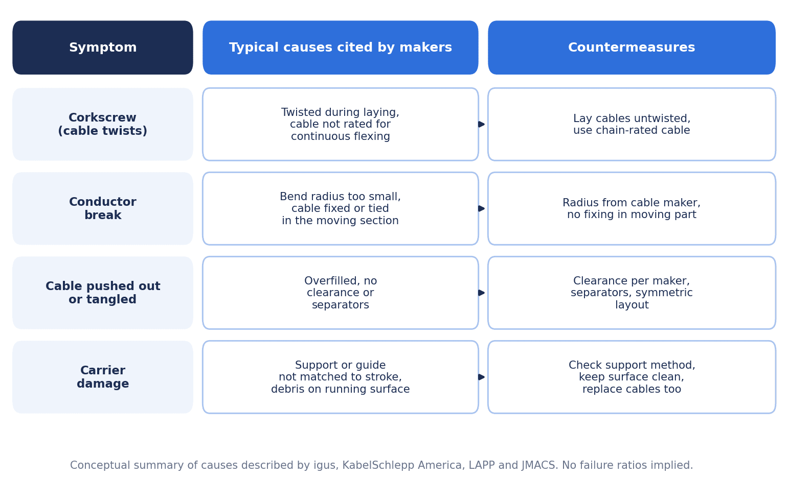
KabelSchlepp America lists the following as symptoms of failure: corkscrewing, knots forming in conductors under the jacket, cables tangling with each other inside the cavity, cables pushing out between crossbars and getting pinched in the bend, jackets tearing from tangling with other cables or crossbars, and loss of continuity from conductor breakage. Based on the companies’ explanations, symptoms, main causes and countermeasures can be organized as follows.
| Symptom | Main causes (from the companies’ explanations) | Countermeasure |
|---|---|---|
| Corkscrewing | Cables not designed for continuous flexing, cables laid while twisted | Replace with continuous-flex cables, lay without twisting |
| Conductor breakage, poor continuity | Insufficient bend radius, overfilling, fixing in the moving section | Review the bend radius, secure clearance, correct fixing positions |
| Cables pushed out or pinched | Overfilling, insufficient separators, cables tangling with each other | Add separators and shelves, review the layout |
| Carrier damage | Unsuitable support method, debris on the running surface, uneven weight | Review the support method and running surface, symmetrical layout |
If the Carrier Breaks, Consider Replacing the Cables Too
JMACS writes that if the carrier (written as ケーブルベア in the company’s document) is damaged, the cables should also be replaced, because they may have been damaged by excessive stress. If problems keep recurring after the cracked carrier was simply replaced with the same size, we recommend treating the carrier damage as a result and reviewing the cables inside, the layout and the motion conditions together.
Fixing (Strain Relief) and Installation Procedure
Fixing Methods Differ by Source
What the companies have in common is that “cables are not fixed or tied in the moving section (the bend zone)”. On the other hand, whether to fix both ends or only one end depends on the source, the type of cable or hose, and the support method.
| Source | Explanation of fixing |
|---|---|
| igus | Strain relief at both ends for round electrical cables. Exceptions such as rotary motion are at the moving end only. States that at a minimum the moving end should be fixed. Hydraulic hoses are generally fixed at the moving end only because they lengthen; pneumatic hoses at both ends |
| KabelSchlepp America | Appropriate strain relief is needed at both ends of the carrier |
| LAPP | In unsupported configurations, fix at both the moving point and the fixed point. For gliding chains, fix only at the moving point and leave a little extra length on the fixed-point side. Hoses at the moving end only. Do not fasten to the carrier links or crossbars with cable ties |
| HELUKABEL | Fix securely at one end of the drag chain and leave room at the other end to absorb movement |
| JMACS | Fix only at the two non-moving ends of the carrier, without tightening strongly. Bundling several cables together and fixing in the moving section are not allowed |
igus recommends keeping the distance from the end of the bend to the fixing point within 10 to 30 times the cable diameter for many cables (the company explains that chainflex can be fixed directly to the mounting brackets). LAPP states that fixing with cable ties is of limited use at high acceleration. The reliable way is to write the instructions of the makers of the cables and carrier you use into the list and agree on the method with the machine builder.
Preventing Twisting and Extra Length
Twisting during installation is named by the companies as a cause of corkscrewing. igus writes that cables should be laid straight without twisting and should not be pulled off over the top of the spool. KabelSchlepp America also explains that cables should not be pulled off over the top of the reel but properly unwound and laid without twisting. LAPP recommends unwinding tangentially from the reel or drum without twisting and laying the cables out straight to settle before installation. It also writes that the printing on the jacket runs in a spiral due to manufacturing, so it cannot be used to check for twisting. It states that the cable temperature during installation should not fall below +5°C.
HELUKABEL explains that before installation the cables should be laid out flat on a level surface without twisting, with extra length of 10% or more of the total length. JMACS writes that kinks should be removed by laying the cable horizontally or hanging it, and that routing cables under tension wears the jacket through friction against the inner walls of the carrier.
Mounting Orientation and Dimensions
MISUMI explains that the fixed end of the mounting brackets should be on the lower side and the moving end on the upper side. igus writes that in long gliding applications there should be a gap of at least 10 mm between the screw heads of the strain relief at the fixed end and the upper edge of the chain.
Beyond the Fixed End: Panel and On-Machine Connections
The wiring beyond the fixed end on the panel side is received by terminal blocks or connectors. How to choose terminals inside the panel is summarized in Control Panel Terminal Block Selection for Thai Factories.
Options to Reduce the Number of Cables Itself
When the contents of the carrier have grown too large, ways to reduce the number of cables are also worth considering. Mounting remote I/O on the moving section lets you replace individual sensor wires with a communication cable and a power cable. A comparison of on-machine remote I/O is covered in Remote I/O Selection – In-Cabinet vs On-Machine, RFP and FAT/SAT for Thai Plants. Sensor signals on moving sections can also be made wireless. For this, see IO-Link Wireless Implementation for Rotating and Moving Machine Parts. Fewer cables also leave more room for fill and clearance.
Reading Service Life Calculations and Guarantees
Service Life Calculations Go Together with Their Assumptions
igus explains that it calculates the number of double strokes with an online service life calculation for e-chains (www.igus.eu/ECS-lifetime) and with a service life calculator for chainflex, and can issue a guarantee certificate. The company writes that the guarantee is based on conditions such as temperature, type of motion, torsion, media and bend radius. As mentioned earlier, it also explains that acceleration has a large effect in the service life calculation.
In other words, service life figures need to be read together with their assumptions. In RFP and acceptance documents, check that the service life calculation states the temperature, type of motion (unsupported or gliding), stroke, speed, acceleration and bend radius.
Example of Guarantee Conditions
igus calls its chainflex guarantee the “4-year guarantee” and states that it runs until the number of double strokes from the online service life calculation or up to 4 years from the delivery date, whichever comes first. It explains that the upper limit is 4 years or 100 million double strokes, whichever comes first, that it applies to new purchases from February 15, 2020 onward, and that damage from incorrect installation or improper use is not covered. For the e-chain itself, it gives a 36-month guarantee.
In the CF9 example, using a cable with a 12 mm outer diameter at a bend radius of 100 mm gives a factor of 8.3. The company explains that within the range of −25 to +90°C this exceeds the minimum factor of 7, so the guarantee is for 10 million double strokes. Outside that temperature range, 8.5 times is needed for 10 million double strokes, so an example is given in which 8.3 times drops the guarantee to 7.5 million double strokes. In other words, even with the same cable and the same bend radius, the guaranteed cycles change with temperature alone.
Initial Elongation and Inspection Intervals
LAPP explains that cables naturally lengthen in the first few hours of operation, while chains lengthen over a long period. On that basis, it recommends inspecting every 3 months in the first year of operation, and after that at each maintenance interval, checking whether the cables move freely in the bend. It also recommends incorporating the maintenance instructions into the equipment inspection plan. JMACS also writes that after operating for a certain time, the cable positions should be checked and adjusted as necessary.
Examples of inspection items are twisting or pushing-out of cables, jacket wear, loosening at fixing points, carrier sag (whether it is approaching critical sag under igus’s categories), and debris on the running surface. For how to set up a maintenance structure for equipment including robots, Robot Maintenance Support 2026: Contract for Recovery, Not Visits may also be useful.
Major Manufacturers, Published Specifications, and How to Check Prices
Below are the main manufacturers referred to in this article and what could be confirmed in their published materials. This does not indicate a recommendation or ranking.
| Manufacturer | Main product groups | What could be confirmed in published materials |
|---|---|---|
| igus | e-chain (cable carriers), chainflex (cables) | Fill and separator rules, guidelines for unsupported, gliding and vertical use, service life calculation and guarantee conditions, cleanroom test results by model |
| Tsubakimoto Chain | ケーブルベア (the company’s registered trademark; TKP-type plastic cable carriers, etc.) | Inner dimensions, bend radius and prices by part number on an online store. A product group of cable guide systems on the Thai subsidiary’s site |
| KabelSchlepp | Cable and hose carriers (TKA series, etc.) | Selection procedure, clearances, failure causes and ways to extend unsupported length in the technical handbook. The handbook states “A member of the TSUBAKI GROUP” |
| MISUMI | Economy series cable carriers | Selection procedure (outer diameter and inner height, 60% of the cross section, bend radius), technical data, display by part number in Japan and Thailand |
| LAPP | Cables such as ÖLFLEX CHAIN | Installation instructions, layout material for Asia, specification sheets by product |
| HELUKABEL | Cables for drag chains | Installation manual, inquiry questionnaire |
Items not written in each company’s materials are treated as not confirmed in published materials. For example, service life values comparing the companies’ products under the same conditions could not be confirmed in published materials.
Where to Obtain Them in Thailand
The following could be confirmed in Thailand. igus lists a phone number (+66 02 587 4899) and an email address as “igus motion plastic thailand” on its Thai-language site (igus.co.th). Tsubakimoto Chain’s Thai subsidiary (Tsubakimoto (Thailand)) explains on its Thai-language site that, as part of the Tsubakimoto Chain group, it sells the group’s products in Thailand and that experienced engineers provide inspection, consultation, selection and technical support. A Bangkok head office and an Eastern branch are listed as locations, and the product menu includes cable guide systems. On MISUMI Thailand (th.misumi-ec.com), MISUMI’s economy cable carriers are displayed by part number, and igus “E2/000” is also listed as a similar product.
How to Check Cable Carrier Prices
Because sales units and tax treatment are not consistent, prices need to be checked together with the part number, unit and date viewed. The following values were viewed on October 15, 2026 and are subject to change.
- MonotaRO: Tsubakimoto Chain TKP-type plastic cable carrier TKP25H15-30W15R28 (inner height 15, inner width 15, bend radius R28) is JPY 139 excluding tax and JPY 153 including tax per link. The listing states that orders must be for 2 links or more.
- MonotaRO: The same series TKP45H25-30W103R125 (inner height 25, inner width 103, R125) is JPY 579 excluding tax and JPY 637 including tax per link.
- MonotaRO: igus EZ chain type Z14 Z14.2.028.0-1 (R28) is JPY 219 excluding tax and JPY 241 including tax per piece (1 link).
- MISUMI (Japan): Economy series medium-load type E-MPD22-40-35-10 (inner height 22, inner width 40, bend radius 35, 10 links) has a regular unit price of JPY 3,220 excluding tax and JPY 3,542 including tax for a set of 10 links and mounting brackets. The regular unit price for the whole series is JPY 3,220 to 29,945 excluding tax.
- MISUMI Thailand: The same part number E-MPD22-40-35-10 is displayed as “฿ 524.81 / ชิ้น”. However, the screen describes this as a standard price and states that registered users are shown the actual price. Whether it includes VAT could not be confirmed from the display.
MonotaRO prices are per link and MISUMI prices are per set of 10 links plus brackets, so the units differ and the prices cannot be compared directly. For igus in Thailand and Tsubakimoto Chain in Thailand, published prices by part number could not be confirmed. For procurement prices in Thailand, the reliable approach is to request quotations from each company with your list and part numbers attached.
RFP Requirements and FAT/SAT Acceptance Criteria
When ordering from a machine builder, writing the carrier and cable requirements into the RFP (request for proposal) also makes the acceptance criteria clear. The following are example items. Numerical targets are for your own company to decide and are given here only as examples.
| RFP item | Example content |
|---|---|
| Contents list | Purpose, type, quantity, outer diameter, minimum bend radius, weight, jacket material, part number, fixed end and moving end. Decide the spare space (e.g., number of cables to be added in future) yourself and state it |
| Basis for the bend radius | The dynamic minimum bend radius from the maker of each cable and hose, and its relationship to the carrier bend radius |
| Fill and clearance | The criteria of the maker adopted, and an explanation that the design stays within them |
| Separators and shelves | Separator positions and spacing, and the basis for the decision |
| Motion conditions | Stroke, speed, acceleration, frequency, operating hours, mounting orientation |
| Support method | Unsupported, gliding with guide trough, vertical. Basis for the unsupported length |
| Environment and type | Chips, coolant, oil, spatter, cleanliness level, and the type and jacket material chosen |
| Cable types and part numbers | Show by part number and data sheet that the cables are for continuous flexing |
| Fixing method | Fixing position (both ends or moving end) and method for each cable and hose |
| Service life calculation and guarantee document | A calculation stating the assumptions (temperature, type of motion, stroke, speed, acceleration) and a document showing the guarantee conditions |
| Spare parts and replacement procedure | Spare cables and links, a replacement procedure, and an estimate of the time required |
| Inspection intervals | When to re-inspect after initial operation, and subsequent inspection intervals and items |
On requesting a service life calculation, igus explains that a guarantee certificate can be requested from its service life calculator. Where a maker can provide such documents, we recommend requesting them, with their conditions.
FAT (Factory Acceptance Test)
| Check item | Example method |
|---|---|
| Whether the cables move freely in the bend | With the upper run at each end of the stroke, check visually and by hand at each position (based on igus’s installation guidelines) |
| Neutral zone | Check that the cables are not pressed against the inner or outer circumference in the bend (based on LAPP’s explanation) |
| Fixing | Whether positions and methods match the list. Whether any cables are tied in the moving section |
| Running surface | Whether it is free of debris and clean (based on KabelSchlepp America’s explanation) |
| Trial run | Run a set number of double strokes (decided by your company) and check for twisting, pushing-out and abnormal noise |
| Documents | Whether the contents list, service life calculation, guarantee document and wiring diagrams are all present |
SAT (Site Acceptance Test)
For the SAT, decide in advance when to re-inspect after running on the actual line. LAPP recommends checking positions and readjusting after a short period of operation, and inspecting every 3 months in the first year. JMACS also writes that positions should be checked after operating for a certain time. If acceptance is completed on the basis of the re-inspection results after initial operation and an operating record for a set period (decided by your company), it becomes easier to sort out initial defects with the machine builder.
Cost and Benefit Model Estimate (Hypothetical Figures)
From here on, the estimate uses hypothetical figures prepared for this article. They are not figures from a real factory.
The assumed site is a Japanese-affiliated auto parts machining plant in Thailand. The moving sections of 3 gantry loaders use cable carriers packed with general-purpose cables, and cable breakage keeps recurring. For each breakage, production stoppage losses and direct repair costs (materials and outside work) are counted as separate cost items. Because repair costs are not included in the stoppage losses, the same event is not counted twice.
| Item | Calculation | Amount |
|---|---|---|
| Line stoppage due to breakage | 4 times/year × average 3 hours × stoppage loss of 12,000 THB/hour | 144,000 THB/year |
| Direct repair costs (cable materials, outside work) | 4 times/year × 15,000 THB | 60,000 THB/year |
| Total (current annual loss) | 144,000 + 60,000 | 204,000 THB/year |
The countermeasure is assumed to be replacing the cables on all 3 machines with continuous-flex high-flex cables, making a contents list and reviewing layout, separators and fixing, and also renewing carriers where necessary.
| Item | Amount |
|---|---|
| Cables | 150,000 THB |
| Carrier renewal, separators | 90,000 THB |
| Work and handling of stoppage during changeover | 80,000 THB |
| Design, FAT/SAT, records | 40,000 THB |
| Total initial cost | 360,000 THB |
| Annual inspection cost | 24,000 THB/year |
| Case | Breakages prevented | Annual benefit | Annual net benefit | Payback period |
|---|---|---|---|---|
| Base case | 4 per year (all) | 204,000 THB | 204,000 − 24,000 = 180,000 THB | 360,000 ÷ 180,000 = 2.0 years |
| Sensitivity (half the events) | 2 per year | 72,000 + 30,000 = 102,000 THB | 102,000 − 24,000 = 78,000 THB | 360,000 ÷ 78,000 ≈ 4.6 years |
The sensitivity case covers when only half the assumed breakages (2 per year) can be prevented, or when there were originally only 2 breakages per year. Stoppage losses become 2 times × 3 hours × 12,000 THB = 72,000 THB, and direct repair costs 2 times × 15,000 THB = 30,000 THB.
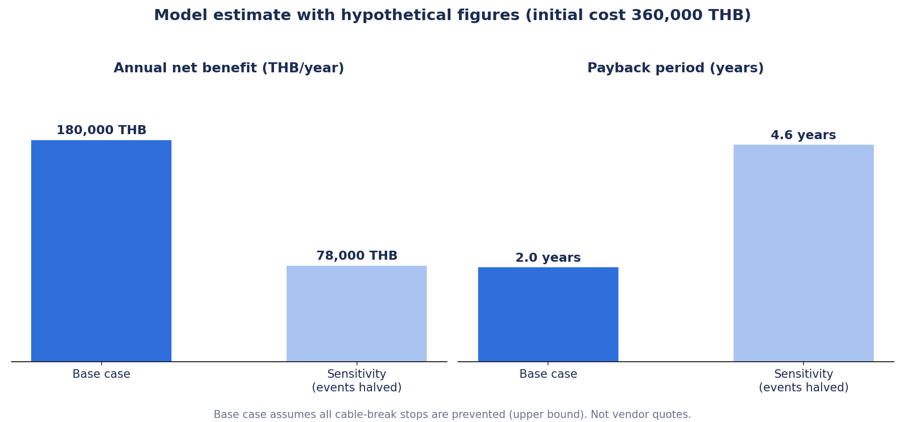
Here is how to read this estimate. The base case figure of 204,000 THB/year is the upper limit, assuming all breakages are prevented. If the cause of breakage is not on the cable side, for example if it is insufficient carrier support, debris on the running surface or acceleration outside the design, the benefit will be smaller. Before deciding on implementation, we recommend counting the frequency and causes from the past year’s breakage records (date and time, axis, cable, symptom). It is also safer not to count the benefit until the SAT and the post-initial-operation inspection have confirmed there is no recurrence.
Frequently Asked Questions
What is the difference between a cable carrier and the Japanese trade name ケーブルベア?
The Japanese name “ケーブルベア” is a registered trademark of Tsubakimoto Chain Co. and is that company’s product name. As generic terms, besides cable carrier, the component is called a cable chain or a cable protection duct, and igus calls its own products energy chains (e-chain). The function is the same: a component that holds the cables and hoses of a moving section and moves them together while keeping the bend radius.
How do you decide the cable carrier bend radius?
igus and MISUMI explain that it is set to match the largest minimum bend radius (the thickest or stiffest item) among the cables and hoses inside. For the cable-side value, use the maker’s dynamic continuous-flex value. Guidelines of “a multiple of the outer diameter” differ by source: JMACS specifies 10 times or more, igus presents 10 times as a rule of thumb, and KabelSchlepp America uses 7.5 times for high-flex cables (when no manufacturer value is available).
What is the maximum cable carrier fill ratio?
There is no single value. JMACS sets a space factor of 30% or less, while MISUMI and KabelSchlepp America set within (or no more than) 60% of the cross section, a twofold difference between sources. On the relationship between outer diameter and inner height, too, MISUMI uses within 80%, while igus and LAPP use the inner height minus clearance (10%). The safe approach is to follow the values of the makers of the cables and carrier you use and, when in doubt, take the stricter one.
Do I need high-flex cables?
For applications where cables are bent millions of times in a carrier, using continuous-flex cables is a prerequisite. KabelSchlepp America lists using cables not designed for continuous flexing as one of the common causes of failure, and explains that many general-purpose industrial cables quickly corkscrew at a small bend radius. Check by part number and data sheet that the dynamic bend radius and bending cycles are stated.
What causes cables to break?
The typical causes named by the companies are concentrated on the cable side, in selection and installation: cables not designed for continuous flexing, overfilling, insufficient bend radius, cables laid while twisted, and fixing or tying in the moving section. A carrier design that does not suit the cables is also listed as one cause. Counting from past breakage records which cable on which axis failed, and with what symptom, makes it easier to narrow down the cause.
How do you estimate cable carrier service life?
Use the maker’s service life calculation together with its assumptions (temperature, type of motion, stroke, speed, acceleration, bend radius). igus explains that it provides service life calculations and conditional guarantees for e-chain and chainflex. Because there are examples where the guaranteed cycles for the same cable change with temperature, check that the conditions are written in the calculation.
What is the cable carrier price?
As viewed on October 15, 2026, on MonotaRO, Tsubakimoto Chain’s TKP type was JPY 153 including tax per link (TKP25H15-30W15R28) or JPY 637 including tax (TKP45H25-30W103R125), and the igus Z14 type was JPY 241 including tax per link. MISUMI (Japan) E-MPD22-40-35-10 is JPY 3,542 including tax for 10 links and mounting brackets. Because the units differ, they cannot be compared directly. In Thailand, the same part number was displayed on MISUMI Thailand at a standard price of ฿524.81, but no VAT category was shown, and published prices by part number for igus and Tsubakimoto Chain in Thailand could not be confirmed.
Summary
- In this article, we take the view that cable carrier selection should not start from the catalog size table but is decided by three things: (1) the list of cables and hoses inside, (2) motion conditions, and (3) environment
- (1) and (2) decide the size and support method; (3) decides the type and jacket material
- The bend radius is decided by the maker’s dynamic minimum bend radius for the thickest or stiffest cable. Guidelines of “a multiple of the outer diameter” differ by source
- There is no single value for fill ratio, the relationship between outer diameter and inner height, or hose clearance either. Follow the values of the maker you adopt and, when in doubt, take the stricter one
- Separate cables of similar diameter placed side by side, and items with different properties, with separators, and place heavy items on the outside, symmetrically left and right
- Lengths that cannot be reached unsupported are handled with gliding, guides or support rollers; for vertical use, conditions differ between hanging and standing
- The typical causes of breakage are concentrated on the cable side: cable type, overfilling, bend radius, twisting and fixing. Buying only a new carrier may not stop recurrence
- Do not fix or tie cables in the moving section; decide between both ends and the moving end by the type of cable or hose, the support method and the maker’s instructions
- In the RFP, ask for the contents list and a service life calculation with its conditions; in the FAT, check both ends of the stroke and the neutral zone; in the SAT, check the re-inspection after initial operation
It is fine if you have not yet decided which cables on which axis to review first. You can consult TOMAS TECH even at the stage of taking stock of breakage records or making the contents list. We work with Japanese-affiliated factories in Thailand from checking the current situation through to the RFP and FAT/SAT. Please contact us here.
References
- the-chain assembly instructions, Laying guidelines, Strain relief, Unsupported, Gliding, Vertical (igus, PDF)
- Bend radius – Minimum bend radius and cable bend radius (igus)
- Energy chains: filling cables and hoses (igus)
- chainflex cables work: 4-year guarantee (igus)
- Jacket material (igus)
- Cleanroom cable carriers (igus)
- What is a corkscrew in a cable and how can it be avoided? (igus Blog, 2020-06-22)
- igus Thailand contact page (igus motion plastic thailand)
- Dynamic Cable & Hose Carrier Systems Technical Handbook, Third Edition (KabelSchlepp America, hosted by Tsubaki Canada, PDF)
- Machine tools, industry solutions (TSUBAKI KABELSCHLEPP)
- Tsubakimoto (Thailand) home page (Thai)
- Technical document: Wiring cables for moving parts (JMACS, PDF, Japanese)
- Installation Manual, Cable installation in drag chains and Questionnaire (HELUKABEL, PDF)
- T3 Assembly guidelines for ÖLFLEX FD/CHAIN and other cables in power chains (LAPP, PDF)
- The right cable layout for drag-chains (LAPP Harnessing Solutions, PDF)
- ÖLFLEX CHAIN 809 7G1,0 (LAPP Vietnam)
- Economy series cable carrier, medium-load type E-MPD22-40-35-10 (MISUMI, Japanese)
- รางกระดูกงู โหลดปานกลาง E-MPD22-40-35-10 (MISUMI Thailand)
- TKP-type plastic cable carrier TKP25H15, Tsubakimoto Chain (MonotaRO, Japanese)
- TKP-type plastic cable carrier TKP45H25, Tsubakimoto Chain (MonotaRO, Japanese)
- EZ chain type Z14, inner width 25, igus (MonotaRO, Japanese)
- PR No.117/2569 Thailand Secures $43.6bn 1H 2026 Investment Surge (Thailand BOI, PDF)
- Thai August factory output rises 4.44% y/y, beats forecast (The Star, Reuters)
- Thailand Car Sales Soar 25.59% in August (Trading Economics)


