


A rotary fixture needs another sensor, but there is no practical cable route. A robot gripper needs condition data, but repeated bending is already stressing its harness. For these retrofit cases, IO-Link Wireless implementation is a machine design decision, not simply a radio purchase. The data path, power on the moving side, coexistence in the 2.4 GHz band, behavior when a link drops, and maintenance all need written requirements. This guide walks a Thai factory team through selection, an RFP, factory acceptance testing (FAT), and site acceptance testing (SAT).
Identify the moving part before choosing wireless equipment
IO-Link Wireless extends the familiar IO-Link architecture with virtual point-to-point radio links between a wireless master and devices. The IO-Link Community describes moving machine parts and difficult cable routes as intended applications. Crucially, a wireless data link does not provide the energy a sensor, bridge, hub, or actuator consumes. Show the power circuit separately on the first drawing. Otherwise a project may remove a signal cable while leaving the cable that actually wears out. The IO-Link Community technology overview describes the architecture; a proposed product combination still needs its own data sheets.
Promising locations include clamp confirmation on a rotary table, fixture seating, grip detection at a robot tool, and status collection from a reciprocating carrier. Each has a signal source that moves. First record why the existing route fails: bending fatigue, twisting, connector wear, slip-ring servicing, or long changeovers. If a fixed sensor can be connected by a short protected cable, wired IO-Link may be simpler. Do not count a wireless benefit until the actual cable, its repair history, and the work needed to add another signal are understood.
Define the use of each value. Clamp confirmation used to advance a machine sequence needs an explicit response and fault behavior. Temperature or vibration collected for analysis can have a different sampling and loss policy. Both may be called “one sensor,” but they cannot share an unexamined acceptance criterion. Record what the PLC does with the value, what a historian records, and how long data can be stale before the operator must act.
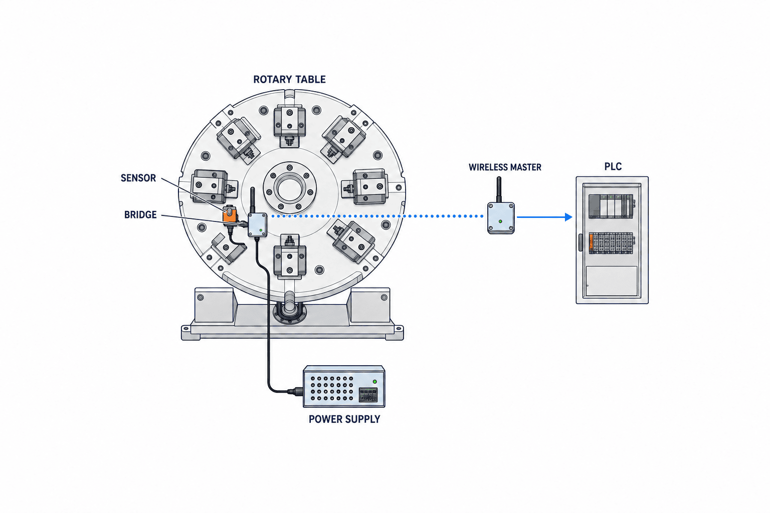
Draw the wired and wireless boundaries
One drawing should show the stationary PLC, industrial network, wireless master, antenna, moving device or bridge, sensor, and power source. Mark the control path, maintenance events, and link-health monitoring. A radio connection does not settle PLC tags, IODD handling, timestamps, alarms, or access rights. The related IO-Link sensor data integration guide explains the data path after the sensor signal reaches the control system.
Some products use a wireless bridge to connect an existing wired IO-Link device. Others collect local sensor inputs in a wireless hub. For a bridge, confirm the original device’s supply, connector, IODD, and supported process data. For a hub, check input count, input type, and short local cables. Compare the topology by signals per fixture, motion envelope, change frequency, and spare parts, not just the headline number of devices per master. Balluff’s application examples include rotary tables and robotic tools, but an example does not certify performance in another factory.
Select an IO-Link Wireless master for the actual machine
Put device capacity, tracks, upstream network, diagnostic access, configuration backup, replacement procedure, installation environment, and local support on the comparison sheet. The IO-Link Community describes an architecture using the 2.4 GHz ISM band, 80 channels of 1 MHz, and time and frequency division. Its overview gives a maximum of 40 devices per master and up to three masters in one airspace. Those are architecture figures, not a guarantee that a selected master, firmware, antenna placement, device mix, and radio environment will deliver that capacity at a particular site. Obtain model-specific specifications and define the number of devices to be proven in the RFP. Keep the version of the published specification and the download page with the design record.
For the upstream connection, confirm the protocol used by the existing PLC, cyclic data mapping, diagnostic status, handling of a disconnected device, and parameter restoration. Compatibility with wired IO-Link concepts is useful, but it does not mean the PLC program can be left untouched. Tags, byte order, data length, quality flags, and alarm logic belong to the actual project. Check cabinet space, supply capacity, available network ports, and permissions for a maintenance computer.
Placement matters. An antenna hidden behind a metal cabinet or moving fixture may behave differently from a bench installation. Check whether master and antenna can be separated, allowed antenna cable length, protection rating, cleaning fluids, dust, vibration, and service access. Log line of sight and shielding throughout the movement. If several masters are proposed, ask the vendor to explain coordination and test the combined installation.
Specify response at the system level
The Community describes a 5 ms cycle in the wireless architecture. It is not the end-to-end response of a sensor-to-PLC-to-output sequence. Detection time, radio transfer, master processing, upstream network, PLC scan, and output actuation all contribute. The RFP should state which values come from a specification and which will be measured during FAT and SAT. For example, a hypothetical 150 ms clamp-confirmation budget is an illustration only, not a standard value or a recommendation for every machine. Break down the actual machine requirement, including jitter and fault handling, with its designer.
Solve power on the rotating side
Possible power arrangements include replaceable batteries, rechargeable packs, a retained 24 V feed, or contactless power transfer. The choice depends on device model, load, operating hours, temperature, cleaning, and service access. A project may sensibly use a radio data path while retaining a suitable power feed. Conversely, if the wearing power cable is the primary problem, removing only the data cable does not solve it.
For batteries, request a life calculation at the intended transmit rate, input count, temperature, and duty cycle. Confirm low-voltage diagnostics in the PLC, access for replacement, settings retained during a swap, and the spare-cell process. For rechargeable packs, document charging and replacement. For contactless power, test air gap, offset, dirt, output capacity, and heat. Balluff’s IO-Link Wireless information shows a possible combination with its inductive couplers; the suitability of a specific pair of products must still be checked.
An illustrative calculation makes the distinction clear: if a sensor plus wireless equipment averaged an assumed 2 W for an assumed 20 operating hours per day, the theoretical energy would be 40 Wh per day. That is not a battery-size recommendation. It excludes startup current, conversion loss, aging, temperature, and reserve. Ask a vendor to supply the design calculation for the real device mix, and test low-voltage behavior.
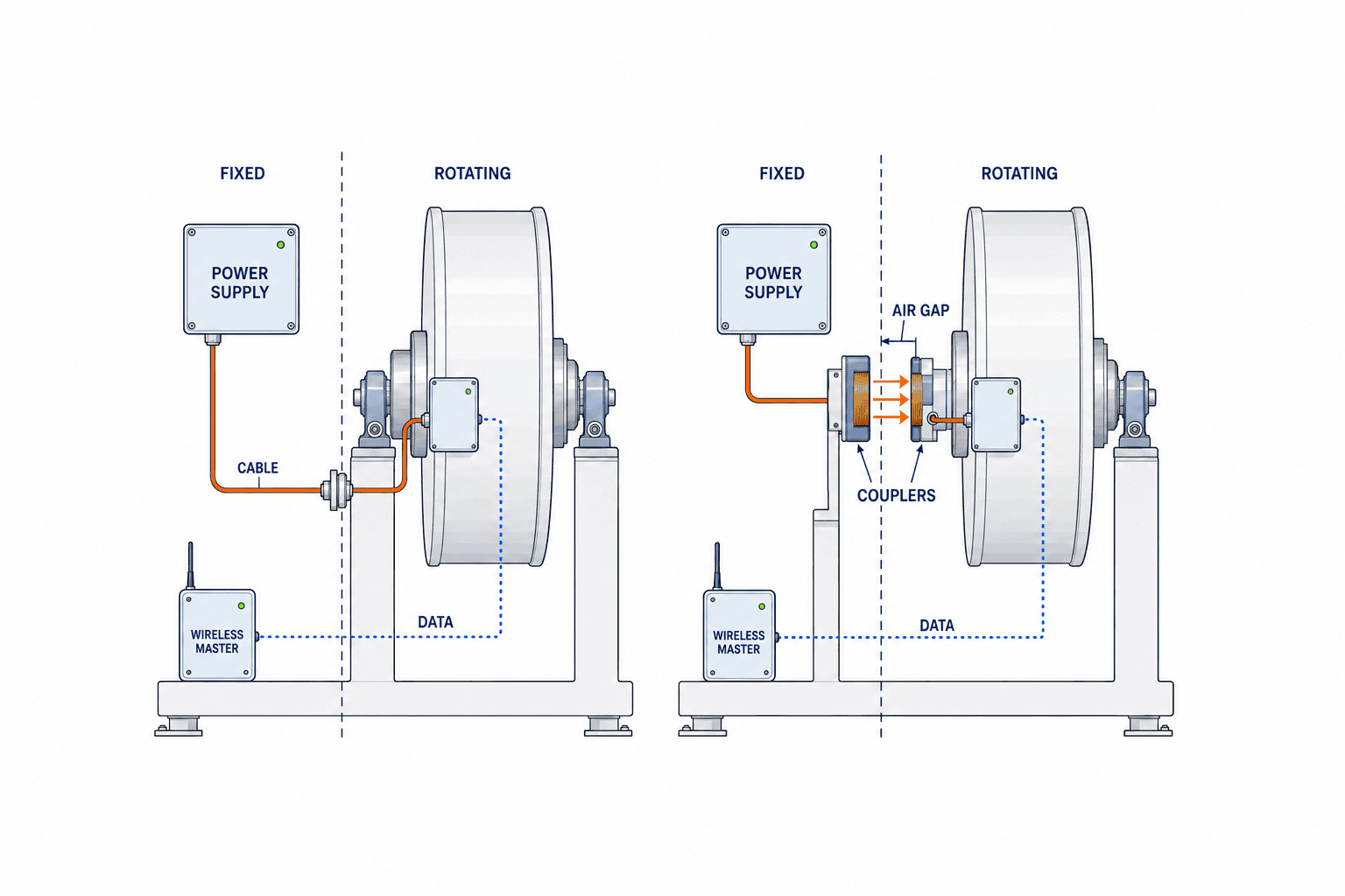
List exactly what cabling the retrofit removes and what remains. If a slip ring still carries other essential power or signals, do not claim that the slip ring has been eliminated. Compare a “wireless data, existing power” option with “wireless data, contactless power” and an improved wired route on the same machine conditions. Include any extra parts and maintenance each option creates.
Plan IO-Link Wireless coexistence in a Thai factory
The 2.4 GHz band may contain factory Wi-Fi, Bluetooth, and other equipment. Frequency-hopping mechanisms do not make site testing optional. Inventory access points, channels, transmit settings, maintenance tablets, metallic fixtures and products, and nearby drives or welders. Observe the system with normal production running, not only in an empty workshop. Move a rotary table through every angle and include acceleration, deceleration, different fixtures, an operator near the cell, cleaning, and changeovers.
Log disconnections, reconnection time, latency, missing data, and the diagnosis actually visible in the PLC. Repeat measurements while adjacent lines run. Agree acceptance thresholds from machine needs and the vendor’s model-specific evidence before testing; document antenna and firmware configuration. If a radio or Wi-Fi setting must change, coordinate with IT/OT owners. Changes can affect another line’s terminals and quality records. Keep a baseline so later access-point additions or fixture changes trigger a repeat survey.
In Thailand, a band described as unlicensed does not mean that equipment is exempt from applicable standards or certification. Have the supplier identify the radio module, antenna combination, importer or installer responsibilities, and documentation applicable to the actual model. Use NBTC public information as a starting point; a public notice alone cannot certify a particular installation. Complete procurement or legal review where required before ordering.
Define link-loss behavior and replacement work
When communication stops, will the PLC hold the last value, mark it invalid, wait, or stop a sequence? The answer depends on the process. A held clamp bit must not silently mean “clamp still closed.” Carry freshness and data quality into control logic and record the count and duration of communication faults. Test reconnection with the expected device identity and parameters.
Do not treat a radio reliability claim as a machine safety approval. Emergency stops, guards, and other safety functions need a separate risk assessment and design. Our IO-Link Safety selection guide covers that boundary. Even for ordinary production data, the machine designer must approve the fault response.
Write a replacement procedure covering device identity, master association, parameter restore, a trial run, and removal of the old registration. Track the IODD version, firmware, backups, change permissions, and log storage. The Community specification describes masters, devices, bridges, and diagnostics; confirm which features each purchased product actually implements.
RFP checklist that can become an acceptance sheet
Attach a matrix with the requirement, vendor answer, evidence, and FAT/SAT test ID. Where the required number is unknown, name the owner and date of a site survey or sample test before comparing prices.
- Process and signals: movement, positions, changeover frequency, sensor models, data lengths, update needs, and the use of each PLC value.
- Topology: master, device, bridge, and hub models and firmware; upstream network; antenna location; cabinet work; expansion plan.
- Power: moving-side load, supply method, capacity calculation, low-voltage diagnosis, and replacement interval.
- Radio: existing Wi-Fi and other systems, survey method, testing with adjacent lines, disconnection and recovery criteria, and retest triggers.
- Machine behavior: PLC and HMI states for link loss, power loss, reconnection, wrong association, alarms, and authorized recovery.
- Local operation: Thai equipment documentation, importer and installer responsibility, spare parts, training language, warranty, and support.
- Acceptance: FAT and SAT conditions, logs, sign-off, retests, as-built drawings, backups, and handover.
Do not copy “maximum range” or “maximum devices” from a brochure into the pass/fail column. Prove the actual device count and positions. A system that works only when an adjacent line is idle has not passed its real use case. A price comparison should include supply, brackets, cabinet and PLC work, radio survey, testing, spares, and training. Use historical maintenance records, and identify assumptions, when estimating a benefit.
Separate IO-Link Wireless FAT and SAT
FAT checks the assembled configuration before shipment: device recognition, IODDs, parameters, every input, lost-link and reconnection behavior, low voltage, logs, backup, and restoration. If full movement cannot be reproduced, mark it explicitly as “not tested at FAT” and assign it to SAT. Passing FAT does not prove the Thai factory’s radio environment.
SAT runs the actual machine with fixtures, workpieces, adjacent lines, Wi-Fi, cleaning, and changeovers. Capture the time from the physical event to PLC input where required, and log missing data, delay, disconnections, and recovery. Deliberately interrupt a non-safety signal under a safe test procedure and confirm PLC/HMI behavior with the equipment owner. Re-test after moving an antenna. Record operating mode, run duration, cycle count, other radios, thresholds, and log method; agree them before FAT. These are examples for a site-specific plan, not universal standard pass values.
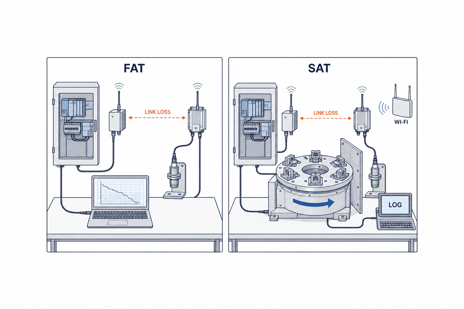
The handover pack should contain wiring and antenna drawings, model and serial numbers, firmware, configuration files, IODDs, PLC tag mapping, radio survey, FAT/SAT records, power maintenance instructions, and Thai compliance documents. State what triggers re-evaluation: a new Wi-Fi access point, metallic fixture change, master move, or firmware change.
Retrofit in stages and review real results
Plan the cutover on a machine that is already running
An as-built machine may differ from its electrical drawing. During the site survey, check more than spare PLC inputs: trace whether the existing signal also feeds an interlock, quality record, production historian, or maintenance display. Replacing a sensor requires a comparison of detection distance and response time, but also mounting threads, connector pinout, protection rating, cleaning chemicals, and the adjustment needed after replacement. A bracket added to a rotating member can change its inertia or balance. Ask the machine builder or responsible engineer to approve that mechanical change. The fact that only a communication route is being changed does not remove the need for machine change control.
One staged approach is to use wireless data for observation while the original wired signal remains the control source. Log both at the same time to expose differences caused by mounting location, detection threshold, or update rate. Parallel signals are useful for evaluation; they do not automatically make an independent safety function. Before cutover, agree which old cables will be removed, every PLC logic change, how to roll back if the trial fails, and who can support the night shift. Record unrelated changes separately. If a Wi-Fi installation and a fixture replacement happen on the same cutover day, troubleshooting becomes needlessly difficult.
Do not accept a new signal merely because a number appears on an HMI. Check that it matches the physical machine in every meaningful state. For a clamp, distinguish open, closed, stopped partway, power removed, sensor failure, and radio loss. For numeric condition data, check engineering units, measurement range, out-of-range values, and timestamps. If events support production traceability, test the association with the correct manufacturing lot or fixture ID. The purpose of capturing data is to leave an interpretable record that helps investigate a later problem.
Compare quotation scope and responsibilities
The purchase price of a master and sensors hides installation costs. Include antenna brackets, moving-side guards, contactless power parts, cabinet supply, industrial-network configuration, PLC and HMI changes, spare parts, site testing, and training in the comparison. A special battery may have a long procurement lead time or storage requirements. For products imported into Thailand, identify the importer, who supplies applicable radio compliance evidence, and who provides local support. Standardize what “complete equipment” includes and what the installer or factory must provide; otherwise two quotations may describe different jobs.
For software, confirm the configuration tool, licenses, firmware update process, backup method, and user permissions. Ask whether settings can be restored if the maintenance PC fails and whether another technician can repeat replacement work years later. The configuration used in testing belongs in the as-built handover. If it is omitted, the next replacement may require undocumented setup on the production floor. Include one acceptance test that restores a backup onto a spare master; it is an efficient way to find missing files or steps in the maintenance procedure.
Expansion cannot be judged by spare ports alone. A new fixture may add shielding; its travel may be different; nearby Wi-Fi may grow. Whether more devices can be added without moving the master is a question for this installation. Put a repeat measurement into the maintenance standard for expansion. Define when a replacement radio unit with a different firmware version also requires retesting rather than assuming it behaves identically.
Compare improved wired routing, wireless data with existing power, and wireless data with contactless power over the same operating period. Include battery-change labor, surveys, backups, and spares. As an illustrative arithmetic example, four cable replacements documented in a year at two labor hours each equal eight direct labor hours per year. This does not establish downtime cost or ROI without site records; do not borrow an unverified savings percentage from a brochure.
Define operating metrics after commissioning
Avoid judging the installation by a general impression that “the machine did not stop.” Record link-loss count, reconnection time, low-voltage alerts, battery changes, cable faults, unexplained stops, and changeover time with the same definitions before and after the retrofit. A small number of link losses can still matter if they cluster just before a critical sequence. Conversely, more diagnostic events may mean faults that were previously invisible are now being captured. Review the logs together with production events before drawing a conclusion.
Create a route from machine change notices to a repeat radio assessment. New access points, temporary wireless equipment, modifications to metal fixtures, line moves, and firmware updates should trigger consideration. Keep the initial SAT logs so later measurements have a baseline. For the operator’s daily HMI, show the equipment to inspect and the recovery action in plain language; a wall of specialist radio metrics is less useful on a running line.
These metrics can also check whether the investment delivered its intended benefit. If records confirm fewer cable repairs or less installation work, use that evidence when considering another machine. If they do not, revisit the selection criteria. Success is measured in machine availability and repeatable maintenance, not simply in the adoption of a wireless product.
Frequently asked questions
Does IO-Link Wireless implementation remove the power cable on a rotary table?
Not automatically. It removes a data path. The sensor and wireless device still need a battery, existing power, or a suitable contactless supply. Determine that from load and maintenance requirements.
Can we design around 40 devices per IO-Link Wireless master?
The Community describes this as an architectural maximum. Confirm the purchased model, firmware, signal mix, tracks, installation, and radio environment in the RFP and acceptance tests.
Can an existing wired IO-Link sensor become a rotating wireless sensor?
A compatible wireless bridge may connect it. Check IODD, power, connector, process-data length, and diagnostics for the particular combination.
Is coexistence proven because factory Wi-Fi already works?
No. Survey channels, locations, metal shielding, operating times, and adjacent lines with the new equipment running. Define retest conditions after changes.
What is the difference between IO-Link Wireless FAT and SAT?
FAT proves configuration and functional behavior under factory test conditions. SAT proves operation on the installed machine in the site’s real radio and production environment.
Conclusion
IO-Link Wireless is worth evaluating where a rotating or moving data cable constrains machine design and maintenance. A sound implementation specifies each signal, solves moving-side power, surveys coexistence, defines fault behavior, checks local equipment requirements, and measures the real installation at FAT and SAT. Keep the removed cables and new maintenance work in the same comparison.
If you are considering a retrofit on a rotary table or robot tool, contact TOMAS TECH while mapping signals, movement, existing wiring, and power. We can help turn the concept into a testable configuration and acceptance plan.


