


Control panel terminal block selection cannot be reduced to “use this part for 2.5 mm² wire.” A wire that will not fit, an incompatible jumper, or an inaccessible test point often becomes visible only during site installation. This guide is for purchasing, electrical engineering, and maintenance teams procuring a DIN-rail terminal strip for a Thai factory. It follows the decision from circuit inventory through the BOM to FAT and SAT. Confirm every capacity and approval against the data sheet of the actual part and the project specification.
Treat the terminal strip as an interface
A terminal block is both an electrical connection and a boundary between cabinet and field wiring, panel builder and installer, operation and testing. A single line on a schematic becomes a real conductor with a material, cross-section, strand construction, insulation diameter, ferrule, entry direction and service loop. If the field cable cannot enter the terminal selected by the builder, a junction box or unplanned rework may be needed before handover. Start with a matching revision of the schematic, terminal schedule, cable schedule, I/O list and layout. Mark who supplies and connects each side.
A signal name alone is not enough for procurement. Classify each position as power, protective earth (PE), analog, digital input, digital output, communications, or a circuit needing isolation or measurement. Record conductor material, solid/stranded/fine-stranded construction, cross-section and number of cores on both cabinet and field sides. Add circuit voltage, continuous current and relevant transients. For a retrofit, compare photographed terminal numbers with the latest drawings before building a BOM; undocumented jumpers and occupied “spare” positions are common causes of rework.
Choose the circuit function and responsibility boundary before choosing a brand. A 24 V DC sensor supply distributed to multiple loads needs a different terminal function from an input that must be disconnected individually for troubleshooting, even where both meet the same current rating. Define the purpose of each strip section. For upstream supply design, see our 24 V DC power supply selection guide; this article focuses on connections downstream of that supply.
Types of control panel terminal blocks by function
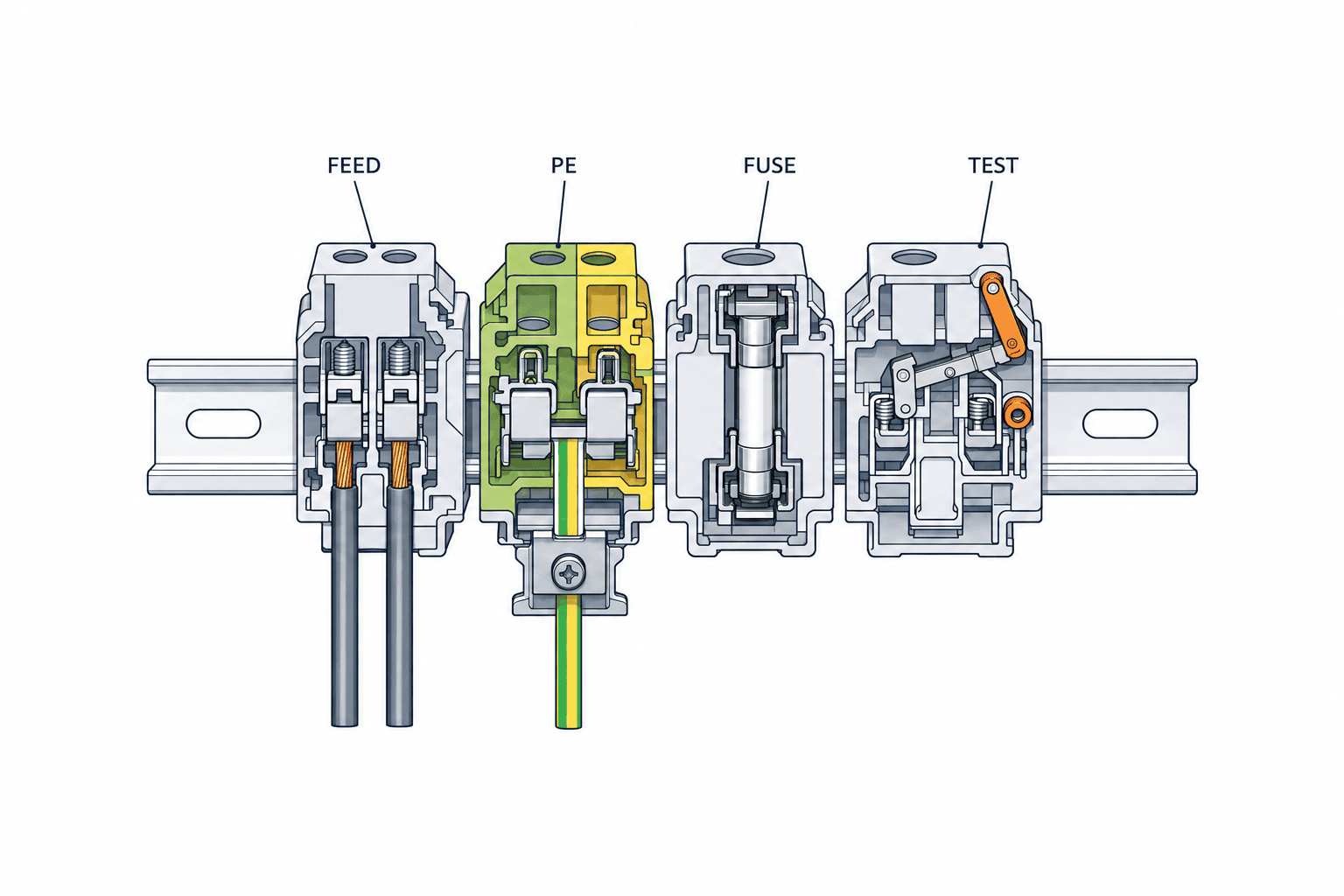
A feed-through block makes a point-to-point connection. A PE block connects a protective conductor to the intended earthing path. A fuse block provides a location for a specified protective device, while disconnect and test-disconnect blocks support isolation and measurement. Multi-level blocks save rail length, but upper and lower access, marker visibility and separation of unlike potentials must be checked. Sensor/actuator distribution or multi-level versions can help with dense PLC I/O, provided the required potential and diagnostic access are preserved.
WAGO lists feed-through, fuse, disconnect, test and sensor/actuator variants plus jumpers and marking accessories in its rail-mount range. Weidmüller groups feed-through, PE, fuse, separation and potential-distribution variants by application. Their catalogs illustrate possible functions; they do not imply that different series or manufacturers are mechanically interchangeable. Match the block, end plate, end clamp, jumper, marker and test plug within the approved system, and document the exact combination in the BOM.
Do not select a PE block by color alone. Verify its rail connection, mounting conditions, conductor range and protective path. For a fuse terminal, specify fuse type, rating, breaking capacity, protection coordination, access during replacement and any indication. Choose disconnect blocks with their expected operation and location in mind. If a test point is required, define the plug and instrument connection in the drawing. Ask maintenance personnel exactly where and under what conditions they will isolate and measure. That question often reveals whether a special function terminal is necessary.
Compare circuit, conductor and product ratings separately
Use three sets of information: the circuit requirement, the cable specification, and the ratings of the selected block and accessories. Record continuous current along with starting, inrush, overload and upstream protection conditions. For the conductor, capture material, cross-section, insulation outside diameter, strand construction, temperature rating and routing method. For each product, read rated voltage and current, permitted conductor ranges, strip length, ferrule compatibility and the conditions for jumpers and adjacent mounting. IEC 60947-7-1:2025 sets requirements for terminal blocks for copper conductors and the test-disconnect blocks covered by Annex D. The limits of that standard’s scope are not the ratings of an individual product.
Phoenix Contact’s PT 16 N RD page, for example, describes one feed-through model. Its connection method, dimensions, approvals and conductor data help assess that model. They must not be copied onto another color, level, rail interface or accessory assembly without checking that item’s documentation. Solid, stranded and fine-stranded conductors can have different permitted ranges; bare and ferruled wire can also differ. Whether two wires may enter one clamping point is determined by the product instructions, not by a technician’s habit.
A block with a current rating above the circuit current does not settle the design. Identify the limiting block, jumper, fuse, wire or protective device. Consider the expected cabinet temperature, nearby heat sources, cable bundles and expansion. Our control panel thermal design guide covers the wider heat problem. A Thai factory may have an air-conditioned electrical room, a production-floor cabinet or an outdoor-adjacent installation; state the actual environment in the RFQ. Voltage, current and conductor fit are separate checks, not one “2.5 mm² terminal” decision.
DIN-rail terminal block connection methods
Screw connections require a specified tool and tightening torque and the correct wire-end preparation. Push-in versions allow the supported conductor to be inserted, but whether fine-stranded wire needs a ferrule, or how to release it, varies by product. Spring-based systems also differ in their operating slot, push-button or lever. WAGO describes three TOPJOB S actuation variants; Weidmüller lists PUSH IN, SNAP IN, screw and tension-clamp options. A technology name alone cannot rank all products for quality or safety. Match the method to the actual conductor, workspace, tools, training and rewiring frequency.
Compare total work, including preparation, inspection, changes and replacement, rather than initial termination time alone. Where circuits are frequently disconnected for maintenance, the release point must be visible and reconnection straightforward. In a crowded panel, a screw that cannot be approached by its prescribed tool creates a service problem. For screw terminals, put the manufacturer’s torque, tool and inspection policy into the work instruction. For push-in or spring systems, specify supported conductors and ferrules, insertion and release steps, and the manufacturer’s retention check. A mixed-brand panel needs explicit tooling and marker rules; visual similarity is not a compatibility test.
A short wire can apply bending force to the clamp even when stripped to the correct length. Too much exposed copper can create a touch or short-circuit risk. Specify a suitable stripping tool, ferrule and crimp tool where required, plus checks for loose strands and pullout. Neither “ferrules are always required” nor “spring blocks never need ferrules” is a sound universal instruction. Define the actual combination of product and conductor.
Put jumpers, marking and strip width in the BOM
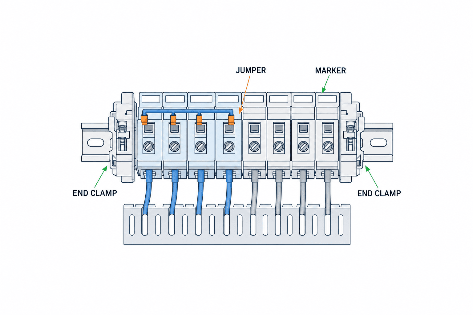
Counting only terminal bodies leaves the assembly short of jumpers or end clamps. Design the complete strip: feed-through, PE and function blocks; jumpers; end plates and clamps; markers; and test accessories. Draw exactly which positions share a potential. Prevent an accidental bridge across unlike potentials through the arrangement, partitions, spare gaps and marking. For a protected supply feeding several circuits, assess both the jumper’s limits and the feed position/current path.
A marker is the key linking the panel to its documents. Relate the PLC address, cable number, terminal number and potential name under one rule, including print orientation. In a multilingual Thai factory, short language-independent terminal IDs can remain fixed while explanations are translated. Spare terminals only support expansion when rail length, duct fill, cable bend space, marker sequence, supply capacity and I/O capacity are also available. Multi-level blocks save area but may make tags and probe points harder to reach.
Add the widths of end components and workable clearance to nominal block widths. Check interference with duct covers and airflow. Verify the rail profile and each mounting foot. Separate strips near field cable entry points may be easier to install than one very long mixed-purpose strip. Evaluate purchase cost alongside assembly, test and future fault-finding time.
Thai factory environment and retrofit constraints
Do not infer cabinet temperature or humidity from the country name. Survey the room temperature range, air-conditioning outages, washdown, oil mist, dust, corrosive atmosphere, vibration and door-opening frequency. A high enclosure IP rating does not guarantee a cool connection point; assess internal heat and cooling separately. If moisture or dust is a problem, address enclosure sealing, placement and inspection intervals as a system, rather than assuming a different terminal alone solves it.
An apparently empty rail is not necessarily available for an extension. Verify neighboring potentials, rail earthing, duct fill and access for maintenance. Photograph and record undocumented bridges, added fuses and duplicate labels before finalizing the design. Investigation or alteration of an energized cabinet must follow the site’s authorization, isolation, voltage verification and qualified-person procedures. State permitted downtime and survey scope in the RFQ; record unknowns as assumptions rather than hiding them.
Where imported and locally sourced parts coexist, check Thai availability of the whole family: jumpers, markers, tools and replacements as well as the terminal itself. A substitute needs a reviewed comparison of ratings, rail fit, wire preparation, labeling, accessory compatibility and approval conditions. Record manufacturer, exact part number, revision, approved alternative and supply route in the BOM so maintenance can replace a single part years later.
Turn current and wire-size checks into RFQ questions
Before specifying a preferred part, give bidders a common set of inputs: voltage, current and protection by circuit; conductor type and size; connection count; expected panel conditions; special blocks; test points; marking; alternatives; documents; and FAT/SAT scope. An “all terminal blocks” line item can hide whether markers, ferrules and test accessories are included. Normalize the scope of wire preparation, installation, testing and site corrections before comparing price.
| RFQ field | Buyer input | Supplier response and evidence |
|---|---|---|
| Circuit | Power, PE, I/O or test/isolation purpose | Proposed block function mapped to terminal schedule |
| Ratings | Voltage, current, protection, environment | Part-specific data sheet and use conditions |
| Conductor | Material, construction, size, ferrule, cores | Permitted combinations, strip length, tools |
| Layout | Positions, common potentials, rail, dimensions | Strip layout, jumper map, clearances |
| Testing | FAT/SAT scope, records, responsibility | Procedure, acceptance criteria, sample record |
| Maintenance | Spares, markers, replacement | BOM, alternate approval, sourcing |
Expand this table by terminal number. A notional X1:01–X1:08 sensor supply group and X1:09–X1:16 input group should state precisely where jumpers start and stop; substitute the project’s real circuit values. Keep drawing revision, part number, price, lead time and approver in one change record. Changing one block can affect the whole strip width or accessory compatibility.
FAT and SAT checks for the selected strip
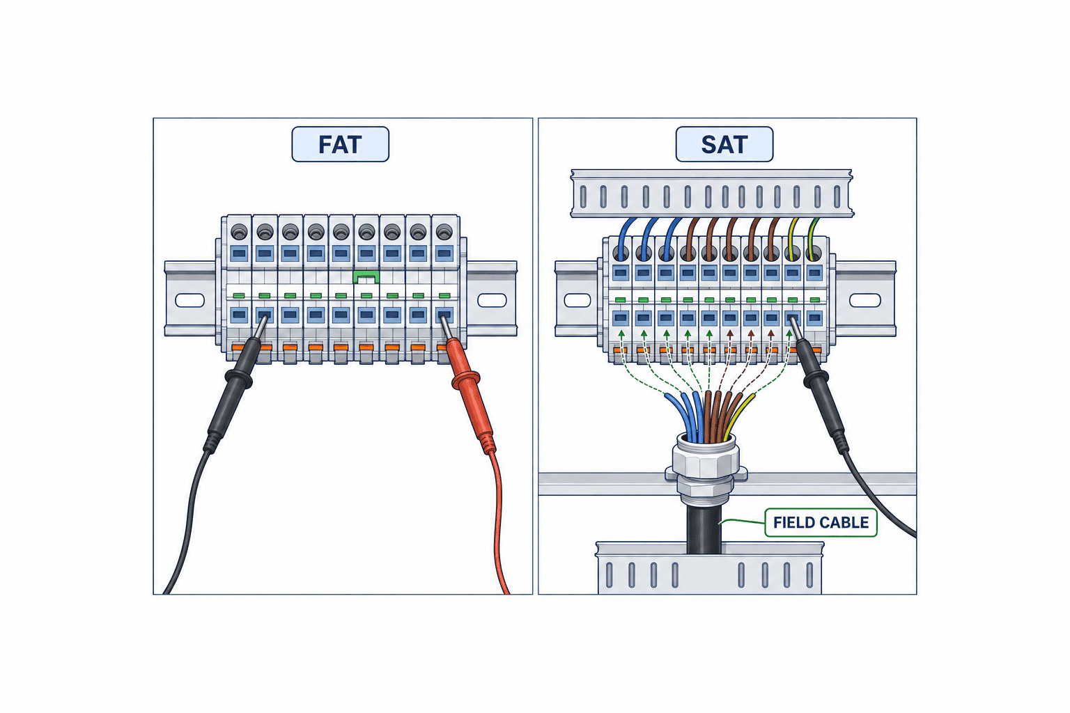
Before energization at FAT, compare physical parts to the BOM. Check part numbers, strip sequence, rail fixing, end clamps, jumpers, PE path, wire IDs, strip length, ferrules and torque or insertion state. For screw terminals, request work records based on the specified torque. For push-in or spring types, follow the maker’s insertion and retention instructions. Visual inspection alone is not a complete acceptance test: schedule drawing-based continuity, insulation, potential and I/O checks. Actual test voltages and pass limits depend on the equipment and project requirements and are not universal numbers here.
Link every FAT discrepancy to terminal number, photo, drawing revision, correction and retest. A jumper shifted one position, poorly mounted PE block, or unexpected external supply can be easy to miss. For test-disconnect circuits, document operating and test positions and require a second restoration check. If field cables are absent at FAT, use data sheets and samples to confirm cable fit, then perform the actual connection at SAT.
At SAT, match installed cable number, conductor, earth/shield treatment, gland, spare length and terminal number. Prove each field signal and action. Routing may reveal a duct cover that will not close or an inaccessible probe point even though FAT passed. Agree downtime, local lockout/isolation procedure and ownership of each supply before testing. Move open FAT items to a SAT punch list with owner, deadline and acceptance method; “check on site” is not a pass record.
Common errors to remove before ordering
First, do not confuse conductor cross-section with a cable’s insulated outer diameter: the clamp needs the former, while ducts and entries need the latter. Second, do not assume bare and ferruled wire of the same nominal size fit identically; read the product’s conductor table. Third, do not stop at the terminal current rating; map jumper, fuse, feed location and branch currents. Fourth, spare blocks alone do not provide expansion without I/O, supply, duct, entry and document capacity. Fifth, similar-looking terminal and jumper series are not proof of compatibility. Sixth, a familiar stripping or crimping habit is not a design instruction; use the selected maker’s preparation details and verify a sample before production.
Seventh, a photograph of a finished strip is not the full FAT record. Pair identified photos and revision data with continuity, I/O, PE and field-connection tests. Eighth, a locally purchased replacement should not be accepted merely because its dimensions look similar. Review ratings, environment, approvals, accessories, tools and spares through change control. These practices align specifications with the physical panel before sophisticated analysis is needed.
A practical selection workflow
Freeze the circuit, cable and I/O inventory, then mark the cabinet/field responsibility boundary. Assign required block functions and maintenance isolation points. Compare conductor construction, size, voltage, current and cabinet conditions against candidate data sheets. Draw the complete strip, including PE, fuse, jumpers, partitions, markers and clamps. Prepare the RFQ and BOM with substitution rules and lead times. Agree termination instructions and FAT/SAT record templates before assembly. Finally hand over the as-built schedule, test evidence and spare-parts list.
Keep panel ID, strip and position number, connections on both sides, cable and core IDs, signal and potential, conductor data, part number, jumper and marker in each terminal-schedule row. Set one owner for revisions across drawing and schedule. When a spare PLC point is used, update not only its address but also terminal, wire ID, jumper, field cable and test record. Convert red-line site changes into the official editable as-built files by an agreed date. Identify unverified positions as “field check pending,” not invented values.
Compare recovery from faults as well as purchase cost. In a large panel, preparation, printing and inspection time may outweigh a small block-price difference; unavailable local tools or spares can delay recovery. Trial-build a representative strip with real wire, ferrules, markers and jumpers. Ask both the wire installer and maintenance engineer to assess access, legibility and replacement. Record lessons from the first panel in the standard BOM and work instructions before repeating the build. Any claimed time saving should be measured in the project’s conditions, not presented as a universal percentage.
This sequence reduces late surprises, but does not replace project-specific decisions on short-circuit levels, protection coordination, machine safety, law or contract obligations. Engineering and installation teams should record the current data sheets, applicable standards, accepted exceptions and design rationale. Whether to standardize on one maker is also a project decision involving compatibility and maintenance burden.
Example: adding eight sensors and two analog points
For an extension of eight sensors and two analog channels, use the I/O and cable lists to count power, return and signal cores. Decide in the drawing where 24 V and 0 V may be shared and where jumpers end. Check supply and branch protection, conductor current capacity, jumper path and how to isolate a failed branch; total sensor current alone is insufficient. Field wire may be larger than panel wire, so verify both sides. Do not automatically bridge future spare positions to the current potential. For analog channels, define shield earthing from the instrument and system design, separation from noise, accessible test points and whether testing requires disconnection. Identify cables by cable, core and terminal number rather than color alone; visibly separate signal and power groups.
Send bidders the circuit-by-circuit schedule, provisional layout, field-cable data, remaining panel space and test-point needs instead of an order for “ten terminals.” Ask for exact part numbers, accessories, wire preparation, rail/duct changes and tests possible at FAT versus SAT. That separates part-price differences from wiring and site-work scope. If downtime is short, assess prewired subassemblies, advance marking and pre-site continuity checks against the surveyed cabinet. At FAT record polarity, continuity, jumper start/end, I/O mapping and labels for all eight sensors; record simulated input, PLC reading, conditions and restoration for both analog points. If field cables are absent, do not mark field termination as passed. At SAT verify each installed sensor and update the as-built terminal schedule with actual wire IDs. Each design row then has a matching acceptance record.
Review the complete terminal strip before approval
Hold a short review of the same strip drawing with the electrical designer, panel builder, site installer and maintenance team. The designer checks circuit function and protection; the builder checks assembly and wiring space; the installer checks actual field cores, conductor and entry direction; maintenance checks readable IDs and test access. Do not assume one party knows all conditions. Record unresolved items by terminal number, evidence needed, owner and due date. If field cable is not yet ordered, add a gate to compare its final conductor size with the design assumption.
Approve the layout together with the part-numbered BOM, current data-sheet revision, jumper schedule, printed marker data, wire-preparation instruction and FAT/SAT checklist. A series change requires checking end parts, jumpers, test plugs and rail interface as well as the terminal body. Request a difference table for a proposed substitute covering electrical ratings, conductor fit, dimensions, work method, tools and Thai spare availability. Control drawing revision, issue date, changes and recipients after approval so the panel shop and site team use the same version for assembly and acceptance.
Summary
Control panel terminal block selection links circuits, conductors, connection methods, special functions, accessories, layout, tests and maintenance in one traceable terminal schedule. For Thai factory procurement, describe cabinet-side and field-side conductors separately, compare bids against the same RFQ and verify each numbered position at FAT/SAT. Keep the scope of IEC 60947-7-1:2025 distinct from the rating of an individual part.
If you have cabinet drawings but still need to define field cable fit, wire preparation or FAT checks, you can share the draft documents through TOMAS TECH’s contact page. We can discuss the interface and RFQ while the project is still being scoped.
Frequently asked questions
How do I choose the type of control panel terminal block?
Start from potential and circuit purpose, then allocate feed-through, PE, fuse, disconnect/test or distribution functions. Verify the actual part and accessories together; color alone is insufficient.
Is screw or push-in better for a DIN-rail terminal strip?
It depends on conductor construction, ferrules, tools, access, rewiring frequency and work instructions. Follow the exact product’s ratings and installation directions for either method.
Is any terminal rated for 2.5 mm² suitable for my circuit?
No. Voltage, current, solid/stranded/fine-stranded wire, ferrules, temperature, jumpers and number of conductors can change suitability. Read the part-specific data sheet.
What belongs in terminal-block RFQ, FAT and SAT documents?
The RFQ should define circuits, conductors, environment, special blocks, accessories, documents and tests. FAT checks the assembled cabinet against drawings; SAT verifies actual field cables, signals, earthing and access. Define pass criteria and responsibilities for the project.


