


Introduction: Servo Motors Cannot Be Selected from the Rated Output (W) Column Alone
Servo motor sizing is sometimes reduced to reading the rated output (W) column in a catalog. A failed motor is replaced with a different model of the same wattage, and the axis starts vibrating and will not settle. Overvoltage or regenerative overload alarms appear every time the axis decelerates to a stop. A vertical axis nearly drops during a power failure. In the Thai hot season the control panel heats up and overload alarms become more frequent. These are the kinds of problems that can occur when a motor is chosen by wattage alone.
Here is the core argument of this article up front. In this article, we take the view that servo motor selection is decided by the following three items.
- (1) Load inertia ratio: the ratio of the load moment of inertia (converted to the motor shaft) to the motor’s own moment of inertia. The recommended or allowable range differs by manufacturer and model
- (2) Peak torque and RMS torque: calculated from a motion profile that defines the acceleration, constant-speed, deceleration and dwell times
- (3) Regenerative energy: whether the servo amplifier and regenerative resistor can handle the energy returned during deceleration to a stop or during lowering
In addition, this article’s position is that (4) the gearbox, holding brake, encoder, communication method, safety function (STO), mounting conditions and ambient temperature should be written into the RFP (request for proposal) and verified at FAT (factory acceptance test, before shipment) and SAT (site acceptance test). The “verify through RFP and FAT/SAT” part of (4) is our own practical view.
Items (1) and (3) look like separate items, but they are not independent. In this article, we take the view that the upper limit of the inertia ratio is determined together with the regenerative handling capacity, the rotational speed and the dynamic brake conditions. This reading is based on public documents from Yaskawa Electric and Mitsubishi Electric. Also, even if the calculation in (2) is correct, the result can change depending on the mounting conditions, the ambient temperature and the holding torque of a vertical axis. Later sections explain these two points based on the manufacturers’ public documents.
This article is not a product recommendation or a ranking. Figures and product functions are taken from each company’s public documents and presented in the form “the company states that…” together with the year the document was issued. All sources were accessed on October 16, 2026. The cost estimate in the second half uses hypothetical figures prepared for this article.
The prior decision of whether to use a servo at all, or an induction motor driven by an inverter, is covered in our article on servo control vs inverter control. This article focuses on how to determine the capacity after the decision to use a servo has been made.
Why Thai Factories Should Revisit Servo Selection Now
Investment in automation continues in Thailand. According to an announcement by the Thailand Board of Investment (BOI) (PR No.117/2569, July 23, 2026), investment promotion applications for January to June 2026 totaled 1,299 projects worth about 1.47 trillion baht, up 37% from the same period of the previous year. Of these, the machinery, automation and robotics sector accounted for 82 projects worth about 13.1 billion baht. Applications under the “Smart and Sustainable Industry” measure, which targets machinery upgrades, adoption of digital technology and introduction of automation and robots, numbered 132 projects worth about 17.2 billion baht.
These are “application” figures. The same announcement gives “approvals” for the same period as 1,300 projects worth about 1.31 trillion baht, which is a separate figure from applications. The approval amount for the machinery, automation and robotics sector is not included in this announcement.
For the robot market as a whole, the International Federation of Robotics (IFR) released World Robotics 2026 on September 24, 2026. According to the IFR, the number of industrial robots operating in factories worldwide in 2025 rose 9% year on year to 5 million units, a record high, and annual installations rose 11% to more than 600,000 units. The IFR states that China installed 354,000 units in 2025, which is almost 3 out of every 5 units worldwide. These are global and China figures. The number of installations in Thailand could not be confirmed in the IFR public documents reviewed for this article.
These are figures for Thailand as a whole or for the world, and they do not directly describe the situation at any individual factory. However, as new or modified transfer axes and vertical axes increase, buyers will more often need to check who determined the servo motor capacity and how. This article organizes how to make that check.
Servo Motor Selection: Three Things to Decide and One to Verify
Manufacturers’ selection procedure follows a similar order
In its Σ-7 Series catalog (issued July 2016), Yaskawa Electric presents the servo motor capacity selection procedure in the following order.
- Determine the machine specifications
- Determine the motion profile
- Calculate the motor rotational speed
- Calculate the load torque
- Calculate the load moment of inertia
- Calculate the load moving power (Po)
- Calculate the load acceleration power (Pa)
- Provisionally select a motor (four conditions)
- Verify the provisionally selected motor (acceleration torque, deceleration torque, RMS torque)
- Finalize the result
The company also suggests using its capacity selection software SigmaJunmaSize+ instead of calculating by hand.
Output (W) is just one of the four provisional selection conditions
For the provisional selection in step 8, Yaskawa Electric lists the following four conditions.
- Load torque TL ≤ motor rated torque
- (Po + Pa)/2 < rated output of the provisionally selected motor < (Po + Pa)
- Motor rotational speed nM ≤ rated rotational speed
- Load moment of inertia JL ≤ allowable load moment of inertia
The rated output condition is only one of these four. Moreover, the provisional selection is followed by verification of acceleration torque, deceleration torque and RMS torque. Our reading is that the output condition cannot be taken on its own to mean “matching the wattage is enough.”
How this article organizes the procedure
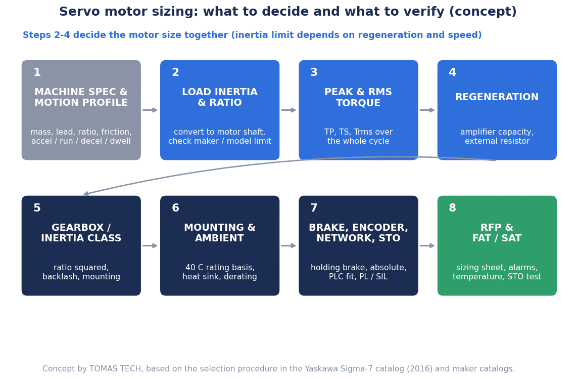
In this article, we organize this procedure into “three things to decide” and “one thing to verify.”
| Category | Content | Main source |
|---|---|---|
| Decide (1) | Load moment of inertia and inertia ratio | Machine specifications, manufacturer rating tables |
| Decide (2) | Peak torque and RMS torque | Motion profile, formulas |
| Decide (3) | Regenerative energy, amplifier and regenerative resistor | Amplifier specifications, regeneration calculation |
| Verify (4) | Gearbox, brake, encoder, communication, STO, mounting conditions, ambient temperature | RFP, FAT/SAT records |
As explained later, (1) and (3) are connected. In practice, the calculation therefore goes back and forth between (1) and (3).
Depending on the application, a stepper motor may be an option instead of a servo. That decision is covered in our article on stepper motor selection.
Machine Specifications and Motion Profile to Collect First
Items to put in a list
Capacity calculation cannot start until the inputs are complete. In this article, we recommend that the buyer prepare the following list, or have the machine builder fill it in.
| Item | Examples | Where it affects the calculation |
|---|---|---|
| Load mass | Total of workpiece, fixture, table and moving parts | Load torque, load inertia |
| Drive mechanism | Ball screw (lead, diameter, length), belt and pulley, rack, etc. | Load inertia, rotational speed |
| Reduction ratio | Gearbox or pulley ratio | Inertia conversion, rotational speed |
| Friction coefficient | Friction of the guide surface | Load torque |
| Mechanical efficiency | Efficiency of the screw and gearbox | Load torque |
| Travel distance and feed time | Travel per move and the time allowed | Motion profile |
| Acceleration, constant-speed, deceleration and dwell times | Breakdown of one cycle | Peak torque, RMS torque |
| Number of cycles | Cycles per minute | RMS torque, regeneration frequency |
| Stopping accuracy | Required positioning accuracy | Encoder, tuning |
| Mounting orientation | Horizontal or vertical (lifting) | Holding torque, brake, regeneration |
| Ambient temperature | Temperature inside the machine and the panel | Rating assumptions, amplifier mounting |
How to select the ball screw itself is covered in our article on ball screw selection, and belt drives are covered in our article on timing belt selection. This article covers the step after those dimensions are fixed, converting them into values seen from the motor side.
Conditions of Yaskawa Electric’s calculation example
The following sections use the calculation example (speed control) that Yaskawa Electric publishes in its Σ-7 catalog (2016). The conditions are as follows.
| Item | Value |
|---|---|
| Load speed | 15 m/min |
| Mass of linear motion section | 250 kg |
| Ball screw | Length 1.0 m, diameter 0.02 m, lead 0.01 m |
| Reduction ratio R | 2 (1/2) |
| Friction coefficient | 0.2 |
| Mechanical efficiency | 0.9 |
| Feed frequency | 40 times/min |
| Feed distance | 0.275 m |
| Feed time | 1.2 s or less |
| Inertia of coupling, etc. JG | 0.40×10⁻⁴ kg·m² |
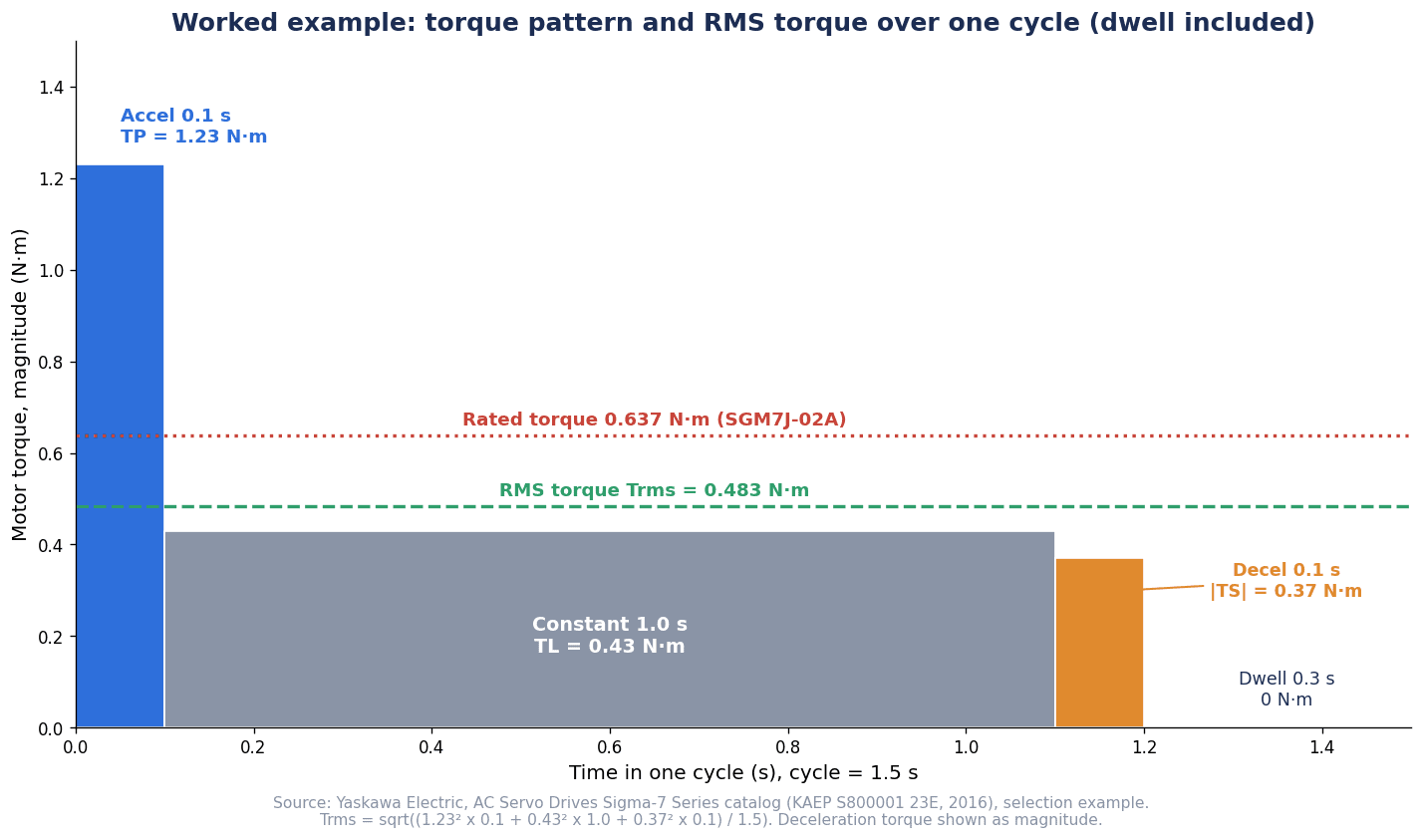
In the motion profile, one cycle is 60 ÷ 40 = 1.5 s. The acceleration time and deceleration time are 0.1 s each, the constant-speed time is 1.0 s, and the remaining 0.3 s is dwell (stopped).
In this example, the motor rotational speed is 3,000 min⁻¹, which is the ball screw speed of 1,500 min⁻¹ multiplied by the reduction ratio of 2. The company calculates the load torque as 0.43 N·m using the formula TL = (9.8·μ·m + F)·PB / (2π·R·η).
The 0.3 s dwell time matters later in the RMS torque calculation. When preparing the list, it is important to write down not only the acceleration and constant-speed times but also the dwell time.
Calculating Load Inertia: Converting to the Motor Shaft
Three components in the calculation example
The load moment of inertia is obtained by converting it to the value seen from the motor shaft. Yaskawa Electric’s calculation example adds the following three components.
| Component | Formula | Value in the example |
|---|---|---|
| Linear motion section JL1 | m·(PB/(2πR))² | 1.58×10⁻⁴ kg·m² |
| Ball screw JB | (π/32)·ρ·ℓB·dB⁴·(1/R²) | 0.31×10⁻⁴ kg·m² |
| Coupling, etc. JG | Component value | 0.40×10⁻⁴ kg·m² |
| Total JL | JL1 + JB + JG | 2.29×10⁻⁴ kg·m² |
Here m is the mass of the linear motion section, PB is the ball screw lead, R is the reduction ratio, ρ is the density of the screw material, ℓB is the screw length and dB is the screw diameter. We also checked the calculation for this article and confirmed that JL1 is about 1.583×10⁻⁴ and JB is about 0.309×10⁻⁴ kg·m², matching the company’s values.
Divided by the square of the reduction ratio
The formulas show that both JL1 and JB are divided by the square of the reduction ratio R. Since R = 2 in the example, JL1 and JB become one quarter of what they would be without a gearbox (R = 1) (this article’s reading of the formula). This formula explains why adding a gearbox lowers the inertia ratio. However, as shown in a later section, the motor rotational speed increases accordingly.
Add the coupling inertia too
JG is easy to overlook. The inertia of parts that rotate with the motor shaft, such as couplings and pulleys, is also part of the load. In the example it is 0.40×10⁻⁴ kg·m², close to 20% of the total of 2.29×10⁻⁴ kg·m². How to select a coupling is covered in our article on shaft coupling selection. Have the inertia value taken from the coupling manufacturer’s documents and entered into the calculation sheet.
What to keep in the calculation sheet
In this article, we recommend asking for JL1, JB and JG to be kept as separate items in the calculation sheet. With only the total, it is impossible to trace what changed when, for example, the fixture is later made heavier or the reduction ratio is changed.
Load Inertia Ratio: Recommended Values Differ by Manufacturer, Model and Conditions
Definition and naming of the inertia ratio
The load inertia ratio is the ratio of the load moment of inertia converted to the motor shaft to the moment of inertia of the motor (rotor). The name differs slightly between manufacturers. Mitsubishi Electric and Panasonic Industry both call it the “recommended load moment of inertia ratio” in their Japanese catalogs. Yaskawa Electric lists it in its tables as “Allowable Load Moment of Inertia (Motor Moment of Inertia Ratio),” in other words as an allowable value. Note that even for the same concept, the wording “recommended” and “allowable” gives it a different standing.
In Yaskawa Electric’s calculation example, the inertia ratio is JL / JM = 2.29 ÷ 0.263 = about 8.7 times, within the allowable value of SGM7J-02A (15 times) (this article’s calculation).
Values by model
The rows in the major manufacturers’ catalogs where the model can be identified are as follows. All of them are the companies’ own descriptions and should be read together with the condition notes.
| Manufacturer, document | Model (conditions) | Inertia ratio |
|---|---|---|
| Yaskawa Electric Σ-7 catalog (2016) | SGM7J-02A (medium inertia, 200 W) | Allowable 15 times (25 times with an external regenerative resistor and an external dynamic brake resistor) |
| Same as above | SGM7J-04A (medium inertia, 400 W) | Allowable 10 times (25 times with the same external devices) |
| Same as above | SGM7A-02A (low inertia, 200 W) | Allowable 30 times (30 times with the same external devices) |
| Mitsubishi Electric MELSERVO-J5 catalog (February 2025) | HK-KT23W (low inertia, 0.2 kW) | Recommended 23 times or less (28 times or less at a rotational speed of 6000 r/min or less) |
| Same as above | HK-KT43W (low inertia, 0.4 kW) | Recommended 23 times or less |
| Panasonic MINAS A6 Family catalog (February 2026) | MSMF 400 W, MSMF042L1□□ (low inertia, for AC200 V) | Recommended 30 times or less |
| Same as above | MHMF 1.0 kW, MHMF102L1□□ (high inertia) | Recommended 5 times or less |
Even within Yaskawa Electric’s Σ-7, the 200 W SGM7J-02A (medium inertia) is 15 times while the SGM7A-02A (low inertia) is 30 times. Even within Panasonic’s MINAS A6, the low-inertia MSMF 400 W is 30 times or less while the high-inertia MHMF 1.0 kW is 5 times or less. What this table shows is that “up to how many times” cannot be stated from the manufacturer or series name alone.
Mitsubishi Electric’s catalog also carries many other notes where the recommended value changes with rotational speed, such as “when the rotational speed is 3000 r/min or less.” Rather than extracting only the figures in the table, the notes also need to be copied into the calculation sheet.
Compare by the absolute value of allowable load inertia, not by the ratio
A motor with a smaller inertia ratio limit cannot be said to be inferior. Even if the limit is small, a motor with a large rotor inertia of its own can accept a larger absolute value of load inertia.
| Model | Rotor inertia | Inertia ratio limit | Allowable load inertia (absolute value) |
|---|---|---|---|
| Yaskawa Electric SGM7J-02A | 0.263×10⁻⁴ kg·m² | 15 times | 3.94×10⁻⁴ kg·m² (company’s calculation) |
| Yaskawa Electric SGM7A-02A | 0.139×10⁻⁴ kg·m² | 30 times | 4.17×10⁻⁴ kg·m² (this article’s calculation) |
| Panasonic MHMF 1.0 kW | 22.9×10⁻⁴ kg·m² | 5 times | About 114×10⁻⁴ kg·m² (this article’s calculation) |
SGM7J-02A and SGM7A-02A differ by a factor of 2 in their inertia ratio limits, yet their absolute allowable load inertia values are close. Even with a limit of 5 times, the MHMF 1.0 kW can handle a much larger load in absolute terms than these two models (although the capacity is also different). In this article, we take the view that when comparing candidates, the sound approach is to compare the “absolute value of allowable load inertia” rather than the “ratio,” together with the conditions under which that value holds.
What happens if the recommended value is exceeded
Mitsubishi Electric notes that if the load inertia ratio exceeds the stated value, customers should contact its sales office. Panasonic also notes “please contact us,” and explains that when high-speed response is required, the motor should be used at a lower inertia ratio. In this article, we therefore read the recommended value not as a line beyond which the motor immediately becomes unusable, but as the boundary at which confirmation with the manufacturer becomes necessary.
Manufacturers that do not state a numerical recommended ratio
Not every manufacturer gives a numerical inertia ratio. Beckhoff describes its AM8500 series as a series with “increased rotor moment of inertia.” The company states that in applications moving large external inertia, the motors are less prone to vibration and tuning on the servo side becomes much simpler. Siemens explains that SIMOTICS S-1FK2 is available in inertia classes, “High Dynamic (HD)” for high acceleration and dynamic performance and “Compact (CT)” for moderate load inertia (2021 document). Rockwell Automation, in the load settings of Studio 5000 Logix Designer, defines Total Inertia = (Load Ratio + 1) × Motor Inertia. This shows that the inertia ratio is both a selection value and a value entered as a servo tuning parameter. The documents obtained from these three companies did not include a numerical recommended ratio.
Peak Torque and RMS Torque: Average Including the Dwell Time
Acceleration torque and deceleration torque
Peak torque occurs during acceleration and deceleration. Yaskawa Electric’s calculation example uses the following formulas.
- Acceleration torque TP = 2π·nM·(JM + JL) / (60·ta) + TL ≈ 1.23 N·m
- Deceleration torque TS = 2π·nM·(JM + JL) / (60·td) − TL ≈ 0.37 N·m
Here nM is the motor rotational speed (3,000 min⁻¹), JM is the motor moment of inertia, and ta and td are the acceleration and deceleration times (0.1 s each). During acceleration, the acceleration torque is added on top of the load torque. During deceleration, the load torque (friction) works in the direction that helps deceleration, so that portion is subtracted.
The company confirms that both TP and TS are below the instantaneous maximum torque of SGM7J-02A, 2.23 N·m, and judges the result “Satisfactory.” Our own check for this article also matched, with TP at about 1.232 and TS at about 0.372 N·m.
RMS torque formula
RMS torque is the root mean square of torque over one cycle and is used as a guide to estimate motor heating. The formula in Yaskawa Electric’s calculation example is as follows.
Trms = √((TP²·ta + TL²·tc + TS²·td) / t)
Substituting the values gives √((1.23² × 0.1 + 0.43² × 1.0 + 0.37² × 0.1) ÷ 1.5) ≈ 0.483 N·m. Since this is below the rated torque of SGM7J-02A, 0.637 N·m, the company judges that the motor can be used under these conditions. Our own check for this article also gave 0.4830 N·m.
The dwell time is in the denominator
What matters in this formula is that the denominator t is 1.5 s and includes the 0.3 s dwell time. The numerator has no term for torque during the dwell. In other words, torque during the dwell is treated as zero and averaged over the whole cycle.
Two things follow from this. First, if the cycle time is tightened and the dwell time shortened, the RMS torque rises even with the same acceleration and deceleration. Second, this formula cannot be used as is for an axis that needs torque while stopped.
Holding torque on vertical axes
On a vertical axis, the motor keeps supporting the weight of the load even while stopped. In this case, torque during the dwell is not zero. Mitsubishi Electric notes in the HK-KT_W specification table that on machines where unbalanced torque occurs, such as vertical axes, the unbalanced torque should be kept to 70% or less of the rated torque. This is a note conditional on vertical axes and is not a figure to apply to every axis. On a vertical axis, the calculation must include the holding torque during the dwell, and the holding brake must be checked, as covered in a later section.
Output condition for provisional selection
In the calculation example, the load moving power is Po = 2π·nM·TL / 60 = 135 W and the load acceleration power is Pa = (2π/60·nM)²·JL / ta = 226 W. The output condition for provisional selection is (Po + Pa)/2 < rated output < (Po + Pa), giving 180.5 W < 200 W < 361 W, and the company provisionally selects the 200 W SGM7J-02A.
Note the order. The output condition is one of four provisional selection conditions, alongside the load torque, rotational speed and inertia conditions. Only after provisional selection under the four conditions, and after checking acceleration torque, deceleration torque and RMS torque, is the selection complete.
Position control calculation example
The same catalog also contains a position control calculation example. It calculates with a linear motion section of 80 kg, a ball screw diameter of 0.016 m, a lead of 0.005 m, an electrical stopping accuracy of ±0.01 mm and a speed diagram that includes a settling time of 0.1 s, and provisionally selects SGM7J-01A. The difference from the speed control example is that position control includes the settling time in the motion profile.
The figure below plots the torque of the speed control example over time. It is 1.23 N·m during the 0.1 s acceleration, 0.43 N·m during the 1.0 s constant-speed section, 0.37 N·m (magnitude) during the 0.1 s deceleration and zero during the 0.3 s dwell. Lines for the RMS torque of 0.483 N·m and the rated torque of 0.637 N·m are overlaid.
Regenerative Energy: Handling the Power Returned During Deceleration and Lowering
When regeneration occurs
When the motor is driven by the load, it acts as a generator and energy returns to the amplifier. This is regeneration. Yaskawa Electric lists the following three situations in which regeneration occurs.
- When decelerating to a stop in acceleration and deceleration operation
- When continuously lowering a vertical axis
- During continuous operation in which the motor is driven by the load (negative load)
Continuous regeneration cannot be handled by the amplifier’s resistor-based regeneration
Yaskawa Electric explains that the resistor-based regenerative processing provided by the servo amplifier cannot be used for continuous regeneration. When regeneration continues, as in tension-controlled feeding or lowering a suspended load without a counterweight, the company states that it needs to be designed as a system that includes a power regeneration converter or similar equipment. Note that this is not a problem that can be solved simply by using a larger regenerative resistor.
The procedure differs by amplifier type
According to Yaskawa Electric’s Σ-7 catalog (2016), among the SGD7S amplifiers, R70A, R90A, 1R6A and 2R8A do not have a built-in regenerative resistor (these are models for which an external resistor is said to be basically unnecessary). Models from 3R8A to 330A have one built in. 470A, 550A, 590A and 780A do not have one built in, and an external resistor is required.
For small-capacity amplifiers without a built-in resistor, the following simplified calculation is used.
ES = J·nM² / 182 [J] (J = JM + JL)
If this rotational energy ES exceeds the regenerative energy the amplifier can process, an external regenerative resistor is added. In the company’s catalog table, the energy that can be processed is 24.2 J for SGD7S-R70A, R90A and 1R6A and 31.7 J for 2R8A with AC200 V input, and 28.6 J for R70F, R90F and 2R1F and 48.4 J for 2R8F with AC100 V input.
For reference, entering the values from the previous section’s calculation example gives ES = (0.263 + 2.29)×10⁻⁴ × 3,000² ÷ 182 ≈ 12.6 J (this article’s estimate). In an actual judgment, the model of the amplifier to be combined is fixed first and compared with the table value for that model.
For amplifiers with a built-in regenerative resistor, the allowable regeneration frequency is obtained with the following formula.
Allowable regeneration frequency = (allowable frequency of the motor alone) / (1 + n) × (maximum speed / operating speed)² (n = JL / JM)
The company explains that if the frequency of the operating cycle is lower than this, no external resistor is required.
Formula for regenerative resistor capacity
For the capacity of an external regenerative resistor, Yaskawa Electric shows the following procedure.
- Rotational energy ES = J·nM² / 182
- Load loss EL = (π/60)·nM·TL·tD (0 if unknown)
- Winding resistance loss EM
- Energy the amplifier can absorb EC
- Energy to be processed by the resistor EK = ES − (EL + EM + EC)
- Required regenerative resistor capacity WK = EK / (0.2 × T)
The company explains that the 0.2 in the formula is the value when the utilization load ratio of the regenerative resistor is 20%. This is Yaskawa Electric’s formula and assumption, and it is not necessarily appropriate to apply the same coefficient to other companies’ products. Check the definition of each symbol in the same catalog.
Mitsubishi Electric notes in its MELSERVO-J5 catalog (February 2025) that because the optimal regenerative option differs by system, it should be selected with its capacity selection software Motorizer. Panasonic explains that MINAS A6 amplifiers in frames A, B, G and H do not have a built-in regenerative resistor and require an optional external regenerative resistor when regeneration occurs, while frames C to F have one built in (an external resistor can also be used).
Inertia ratio and regeneration are linked by formula
This is where (1) the inertia ratio and (3) regeneration connect.
In its MINAS A6 catalog (February 2026), Panasonic explains that the regenerative brake frequency in its table is “the allowable frequency when the motor alone decelerates to a stop from the rated rotational speed.” The company states that with a load attached, the value becomes 1/(m+1) of the table value (m = load moment of inertia / rotor moment of inertia), and that when used above the rated rotational speed, the allowable frequency is inversely proportional to the square of (operating speed / rated speed). For example, with an inertia ratio of 10 times, the allowable frequency is one eleventh of the table value. For models marked “no limit” in the table, the company notes that there is no restriction on regeneration frequency as long as the RMS torque is within the rated torque.
Yaskawa Electric explains that the allowable load moment of inertia value is determined by the regenerative processing capacity of the amplifier and is also affected by the motor’s operating conditions. The company states that if the allowable value is exceeded, an overvoltage alarm (A.400) is more likely during deceleration, and on amplifiers with a built-in regenerative resistor, a regenerative overload alarm (A.320) may occur. If the value is exceeded, the company advises applying a torque limit, easing the deceleration or lowering the maximum speed, and if that is not possible, adding an external regenerative resistor.
The fact that, in the table in the previous section, the allowable value of SGM7J-02A rises from 15 times to 25 times with an external regenerative resistor and an external dynamic brake resistor is consistent with this explanation. In this article, we take the view that the upper limit of the inertia ratio is not a value inherent to the motor alone, but is determined together with regenerative handling, rotational speed and the dynamic brake conditions.
Add a Gearbox or Change the Motor’s Inertia Class?
What a gearbox changes
When the inertia ratio is too large, a gearbox is a commonly used remedy. As shown in an earlier section, the load inertia converted to the motor shaft is divided by the square of the reduction ratio. Siemens also lists “Adjustment of speed and torque” and “Adjustment of inertia ratio (load / motor)” as purposes of S-1FK2 geared motors (2021 document).
However, raising the reduction ratio increases the motor rotational speed needed to achieve the same load speed. In Yaskawa Electric’s calculation example, 1,500 min⁻¹ on the ball screw side becomes 3,000 min⁻¹ on the motor side with a reduction ratio of 2. As the rotational speed rises, it approaches the rated rotational speed condition. According to Panasonic’s explanation, when used above the rated rotational speed, the allowable regenerative brake frequency becomes smaller in inverse proportion to the square of (operating speed / rated speed). The reduction ratio is a value determined by balancing the inertia ratio and the rotational speed.
Specification items that increase with a gearbox
Adding a gearbox increases the items to be checked.
For its GR series of gearboxes for servo motors, Mitsubishi Electric states a backlash of 8 arc-minutes or less for the standard specification and 3 arc-minutes or less for the high-precision specification. The protection structure is IP65, but the mounting surface between the gearbox and the servo motor and the shaft-through portion are outside the scope of this rating. The company states that the gearboxes support a motor maximum torque of 350% and a maximum rotational speed of 6700 r/min. The company also notes that some geared motors (such as HK-ST352(4)G1/G1H) cannot be mounted tilted in the axial direction or the shaft rotation direction.
In other words, with a gearbox, backlash, the scope of the protection rating and the mounting orientation become specification items. Siemens explains in its 2021 document that gearboxes for S-1FK2 are not sold separately and are supplied only as a motor and gearbox unit. The procurement format also differs by manufacturer.
How to choose a gearbox type is covered in our article on gearbox reducer selection.
Changing the inertia class on the motor side
The other remedy is to increase the inertia on the motor side. Beckhoff explains that because the AM8500 series has a large rotor inertia, the motors are less prone to vibration in applications moving large external inertia and tuning on the servo side becomes much simpler. Siemens has the HD and CT inertia classes, Yaskawa Electric has medium inertia (SGM7J) and low inertia (SGM7A), and Panasonic has low inertia (MSMF) and high inertia (MHMF), so these manufacturers offer series with different inertia.
Which remedy fits depends on the size of the load, the required speed, the installation space and the allowable backlash. In this article, we recommend asking for a calculation sheet that lays out both options, adding a gearbox and changing the motor inertia class, side by side by absolute allowable load inertia and rotational speed.
Mounting Conditions and Ambient Temperature: The Rating Assumptions That Matter in Thai Factories
Yaskawa Electric’s ratings assume 40°C ambient and heat sink mounting
The rated torque in a catalog is not a value that can be achieved with any mounting. In its Σ-7 catalog (2016), Yaskawa Electric describes the ratings as “continuous allowable values at an ambient temperature of 40°C with a heat sink attached to the motor.” The company also states that if the motor is mounted on a small member, heat dissipation may be insufficient and the temperature may rise significantly. On that basis, it asks users to check the motor temperature on the actual machine.
The company further explains that derating (using the motor at a reduced rating) is required when the ambient temperature exceeds 40°C (up to a maximum of 60°C) or at altitudes above 1,000 m.
A correct RMS torque calculation is not enough
The RMS torque calculation in the previous section rests on these rating assumptions. Even if the calculation is within the rated torque, the temperature may rise under conditions such as mounting the motor on a thin sheet-metal bracket or poor ventilation inside the machine. Yaskawa Electric also explains that mounting the motor on a small member can cause the temperature to rise significantly. In this article, we take the view that mounting conditions and ambient temperature are also part of capacity selection.
Temperatures inside the machine and the panel differ by factory and by installation location. In this article, we therefore recommend measuring the temperature inside the machine and the panel at the location where the equipment will be installed, and checking the motor temperature after continuous operation at FAT/SAT.
Amplifier mounting and heat from regenerative options
Amplifiers also have temperature conditions. Mitsubishi Electric notes that when MELSERVO-J5 amplifiers are mounted side by side in close contact, the ambient temperature should be 0 to 45°C or the effective load ratio should be 75% or less. There is also an effective load ratio condition of 75% or less when a motor above 750 W is used with a single-phase power supply. These are conditional notes on the amplifier side.
Regenerative resistors also generate heat. Mitsubishi Electric notes that regenerative options rise 100°C or more above the ambient temperature, so heat dissipation, mounting position and the wires used should be carefully considered in their placement. Once the previous section leads to a decision to add a regenerative resistor, where to put it in the panel and whether there are heat-sensitive devices nearby need to be decided at the same time. How to choose a control panel cooling method is covered in our article on control panel thermal design and cooling.
Encoder and Brake: Absolute, Battery and Holding Brake
Check the encoder by “what is needed”
Each manufacturer describes servo motor encoder specifications differently.
- Mitsubishi Electric states that HK-KT is equipped with a batteryless 26-bit encoder that can be used for both absolute position and incremental detection (67,108,864 pulses per revolution) (2025 catalog)
- Panasonic describes the MINAS A6 rotary encoder as a 23 bit absolute (8388608 per revolution). The company states that there is also a batteryless absolute encoder type that reduces battery use by mounting a power generating element in the motor. On the other hand, it explains that the A6SE series, a type dedicated to position control, does not support an absolute system (2026 catalog)
- Yaskawa Electric explains that for Σ-7, 24-bit absolute or incremental can be selected by a digit in the model code. Its 2016 catalog states that a battery case is required when an absolute encoder is used
- Beckhoff states that AM8500 is equipped with a 24-bit SIL 2 safety encoder as standard
It is not possible to say which is better by comparing the number of bits. In this article, we recommend confirming three points in the RFP: whether absolute is required (whether you want to avoid homing after power is cycled), whether a battery is required (whether battery replacement maintenance arises), and whether the amplifier side supports absolute (as in Panasonic’s A6SE example). Encoder types and output concepts are covered in our article on rotary encoder selection.
The brake is for holding and cannot be used to stop the motor
On vertical axes, whether a holding brake is needed becomes an issue. At that point, it is important not to misunderstand the role of the brake. All three companies state clearly that the brake is for holding.
- Mitsubishi Electric: the electromagnetic brake is for holding and cannot be used for braking. The small-capacity brake on HK-KT is a non-excitation type (spring-actuated) safety brake, DC24 V
- Panasonic: a holding brake that is released when energized, and it cannot be used for braking while the motor is rotating
- Yaskawa Electric: the holding brake cannot be used to stop the motor. The company does not supply the 24 VDC power supply for the brake
Stopping the motor is the job of the motor and amplifier; the brake is for holding after the motor has stopped. Who provides the brake power supply is also an item to write in the RFP.
Prices change with a brake
Whether a brake is included also affects the price. In the price list of Mitsubishi Electric’s MELSERVO-J5 catalog (February 2025), the standard price of HK-KT43W (0.4 kW) is 131,000 yen, and 190,000 yen with a brake (both excluding tax). Deciding which axes need a brake at the same time as the capacity calculation makes quotations easier to compare.
Protection Rating and Communication
IP ratings come with conditions
A motor’s protection rating (IP) does not necessarily apply to the whole motor.
- Mitsubishi Electric describes HK-KT_W as totally enclosed, self-cooled with protection rating IP67, but the shaft-through portion is outside the scope of this rating. It notes that if IP67 cables are required, customers should inquire separately
- Yaskawa Electric describes SGM7J and SGM7A as totally enclosed, self-cooled, IP67. It notes that the rating does not apply to the shaft opening and is valid only when the dedicated cables are used
- Panasonic describes MINAS A6 as IP65 for the lead wire type and IP67 for the connector type (IP67 for □80 mm or smaller is made to order). The company notes that it cannot be applied to uses that require waterproof performance over a long period, such as constant washing with water
In this article, we recommend writing in the RFP not only the IP number but also whether washing is involved, whether cutting oil or coolant will splash on the motor, and whether the requirement covers the cables and connectors.
Match the communication method to existing equipment
Support for communication between the amplifier and the host differs by manufacturer.
- Mitsubishi Electric explains that MELSERVO-J5 has amplifiers for CC-Link IE TSN (MR-J5-G), SSCNETⅢ/H (MR-J5-B) and a general-purpose interface (MR-J5-A). The company states that the -N1 type supports EtherCAT and the safety communication Safety over EtherCAT
- Panasonic explains that MINAS A6 has two types of network amplifiers, for EtherCAT and for Realtime Express (RTEX)
- Yaskawa Electric explains that Σ-7 has command types such as EtherCAT and PROFINET in addition to the MECHATROLINK-III command type
- Fuji Electric explains that ALPHA7 supports SX bus and EtherCAT
There is little point in comparing communication methods for superiority. This item is decided by what the PLC or motion controller on the existing line supports and which tools the maintenance staff are familiar with. Overall procurement of servo control, including the interface with the host, tuning and commissioning, is covered in our article on servo control procurement and FAT/SAT.
Safety Functions: STO Alone Does Not Determine the Safety Level
What STO is
STO (Safe Torque Off) is a safety function that electronically cuts off the energy driving the motor. Mitsubishi Electric describes MELSERVO-J5’s STO as a function that electronically cuts off the motor’s driving energy based on an input signal from external equipment, and states that it corresponds to stop category 0 of IEC/EN 60204-1. The company notes that STO should be executed in the servo-off state or after the motor has stopped. Fuji Electric also explains that ALPHA7’s STO cuts off the amplifier output and puts the motor in a free-run state.
In other words, STO is a function that removes torque, not a function that decelerates and stops the motor. On a vertical axis, once the torque is removed, the load tends to move down under gravity. To prevent a drop, holding brakes and functions that control the brake safely (SBC) need to be considered separately.
Position of the standard
STO is one of the functions defined in IEC 61800-5-2 (the standard on functional safety of adjustable speed electrical power drive systems). As of October 16, 2026, the edition listed on the IEC Webstore is Edition 2.0 (published April 18, 2016), and the same page shows Stability date 2026 and an “Under development” indication. This suggests that work on the next edition is under way, but its content has not been confirmed.
The achievable safety level changes with model and wiring
Even if a product says “with STO,” which safety level (PL, SIL) it reaches depends on the model and conditions.
- Mitsubishi Electric describes MR-J5-G, -B, -A and others as category 3 PL e, SIL 3, and MR-J5-G-RJ and others as category 4 PL e, SIL 3. The STO shut-off response time is 8 ms or less when using an input device and 60 ms or less when using CC-Link IE TSN or EtherCAT, and the mission time is 20 years
- Panasonic describes the safety parameters of MINAS A6 as SIL3, PLe, Cat.3 with diagnosis by EDM (external device monitoring), and SIL2, PLd, Cat.3 without diagnosis. The mission time is 15 years. The company states that the A6SE, A6SG, A6NE and A6BE series do not support functional safety standards
- Fuji Electric explains that ALPHA7 has STO as standard and supports SS1, SLS, SBC and SSM with the functional safety option WSU-ST1, with specifications of ISO 13849-1 Cat.3 PL-d, IEC 61508 SIL2 and IEC 62061 SIL CL2
- Yaskawa Electric explains in its Σ-7 400 V product catalog (2018) that all Σ-7 amplifiers have STO as standard and meet the requirements of SIL 3 and PL-e. SS1, SS2 and SLS are added with a safety module
Even with the same Panasonic amplifier, the achievable level changes depending on whether EDM wiring and diagnosis are present. Writing only “with STO” in the RFP does not guarantee that the required safety level will be reached.
On periodic testing
Mitsubishi Electric states in its catalog that no special function check test is required within the mission time of the safety monitoring function, and that IEC 61800-5-2:2016 recommends testing the system at least once every 3 months for category 3 PL e, SIL 3. This is Mitsubishi Electric’s statement, and we have not checked the text of the standard for this article. The test frequency is determined by the explanation of the manufacturer of the equipment adopted and by your own risk assessment.
What to write in the RFP
In this article, we recommend writing the following three points on safety in the RFP. (1) The required PL or SIL as the result of the risk assessment. (2) The wiring and diagnosis conditions needed for that level (such as whether EDM is used). (3) How a vertical axis is held after being stopped by STO (holding brake, SBC, etc.). The approach to the circuit that connects emergency stop switches and door switches with STO is covered in our article on safety relay selection.
Tuning Functions and Vibration Control: What to Leave to Auto-Tuning
Manufacturers’ tuning functions
Each company offers functions that assist tuning.
- Mitsubishi Electric describes quick tuning, which automatically applies vibration before operation and adjusts control gains and machine resonance suppression filters in 0.3 seconds, one-touch tuning, and advanced vibration suppression control Ⅱ (3-inertia system), which suppresses two low-frequency residual vibrations of about 100 Hz or less at the same time. The company states that there are also a command notch filter (about 1 Hz to 2000 Hz), machine resonance suppression filters (10 Hz to 8000 Hz, 5 filters) and a machine analyzer that identifies the machine’s resonance frequency
- Panasonic describes real-time auto-tuning that identifies the load moment of inertia in real time, automatic and manual damping filters, and an inertia ratio switching function
- Yaskawa Electric describes a tuning-less function that it says operates stably without gain adjustment up to an allowable load inertia ratio of 30 times (max.), and a function that suppresses two low-frequency vibrations at the same time (2016 catalog)
- Fuji Electric states that the new vibration suppression control of ALPHA7 reduced vibration at the tip of the equipment to about 1/10. This is the company’s comparison against its own products. It also states that it controls low-frequency vibration at two points simultaneously using a 3-inertia system model
What tuning can and cannot fix
Auto-tuning is a function that searches for gains suited to the machine’s rigidity within the range of the inertia ratio. Capacity problems such as an inertia ratio far beyond the recommended or allowable range, regeneration that cannot be fully processed, or RMS torque above the rating are not solved by tuning. In the example from the introduction, “it vibrated after being replaced with a motor of the same wattage,” a change in the inertia ratio is suspected as one of the causes.
In this article, we position tuning as “the process of suppressing remaining vibration, on the premise that the capacity calculation is correct.” For that reason, ask for the tuning results to be kept as records. If there is a function that estimates load inertia, such as Panasonic’s real-time auto-tuning, the estimated inertia ratio can be checked against the value in the calculation sheet. In a Rockwell Automation environment, the Load Ratio remains as a setting value. If the calculated and actual values differ greatly, it is a sign that one of the assumptions is wrong.
Public Information from Major Manufacturers and How to Check Prices
Comparison of public documents
The scope of public documents checked for this article is organized below in alphabetical order by manufacturer. This is not a ranking of products, but a list of how far things could be confirmed in public documents.
| Manufacturer | Document obtained and year of issue | Statement of recommended inertia ratio | Capacity selection tool | Description of STO |
|---|---|---|---|---|
| Beckhoff | AM8500 product page (no year of issue stated) | No numerical value (described as a series with increased rotor inertia) | Not confirmed in the documents obtained | Not confirmed in the documents obtained (describes a 24-bit SIL 2 safety encoder as standard) |
| Fuji Electric | ALPHA7 catalog (prepared January 2021) | Not confirmed in the documents obtained | Not confirmed in the documents obtained | Described as STO as standard, resulting in free-run. PL-d, SIL2 with WSU-ST1 |
| Mitsubishi Electric | MELSERVO-J5 catalog (February 2025) | Recommended values per model with notes on rotational speed and other conditions (e.g. HK-KT23W 23 times or less) | MELSOFT Motorizer | Described as equivalent to stop category 0. Category 3 or category 4, PL e, SIL 3 depending on the model |
| Panasonic (Panasonic Industry) | MINAS A6 Family catalog (February 2026) | Recommended values per model (e.g. MSMF 400 W 30 times or less, MHMF 1.0 kW 5 times or less) | Not confirmed in the documents obtained | Described as SIL3, PLe or SIL2, PLd depending on whether EDM diagnosis is used |
| Rockwell Automation | Studio 5000 Logix Designer 38.00 Help (no year of issue stated) | No numerical value (Load Ratio defined as a setting value) | Not confirmed in the documents obtained | Not confirmed in the documents obtained |
| Siemens | S-1FK2 webinar material (April 2021) | No numerical value (HD and CT inertia classes) | TIA Selection Tool | Not confirmed in the documents obtained |
| Yaskawa (Yaskawa Electric) | Σ-7 catalog (July 2016), Σ-7 400 V product catalog (December 2018) | Allowable values per model (e.g. SGM7J-02A 15 times) | SigmaJunmaSize+ | Described as STO as standard on all Σ-7 amplifiers, SIL 3 and PL-e |
“Not confirmed in the documents obtained” does not mean that the function or statement does not exist. It means that it could not be confirmed within the scope of the documents obtained for this article. When checking with the machine builder, asking for the output of the capacity selection tool (the calculation sheet) to be attached as is makes it easier to trace the assumptions.
How to check prices
Publicly available servo motor price figures are of mixed types. The figures confirmed for this article are shown below, separated by type.
The price list in Mitsubishi Electric’s MELSERVO-J5 catalog (February 2025 edition) gives domestic “standard prices” in Japan, excluding consumption tax. These are not actual selling prices. In this list, the HK-KT_W servo motor (3000 r/min) is 88,500 yen without a brake and 136,000 yen with a brake for HK-KT13W (0.1 kW), and 131,000 yen without a brake and 190,000 yen with a brake for HK-KT43W (0.4 kW). The MR-J5-G amplifier (CC-Link IE TSN, 200 V) is 152,000 yen for MR-J5-20G (0.2 kW) and 159,000 yen for MR-J5-40G (0.4 kW). The functional safety model HK-KT43W(B)WS (0.4 kW) is 150,000 yen without a brake and 209,000 yen with a brake.
On the online retailer MonotaRO, as viewed on October 16, 2026, Yaskawa Electric’s Σ-7 SGM7J was listed at the following selling prices. SGM7J-04AFA21 (0.4 kW, without brake) was 49,980 yen excluding tax and 54,978 yen including tax, shown as out of stock with an expected shipping date of early March 2027. SGM7J-04AFA2C (0.4 kW, with brake) was 69,980 yen excluding tax and 76,978 yen including tax, and SGM7J-02AFA21 (0.2 kW, without brake) was 39,980 yen excluding tax and 43,978 yen including tax, both shown as currently suspended (not available for order). Stock and availability indications change. These are prices for the motor alone and do not include the amplifier, cables, gearbox or regenerative resistor.
Because the manufacturer’s standard price (excluding tax) and an online retailer’s selling price are different types of prices, they cannot be lined up side by side for comparison. Brake options and capacities also differ. Manufacturer standard prices for Panasonic and Fuji Electric could not be confirmed in the documents obtained this time. Public prices for servo motors within Thailand could not be confirmed either. When procuring in Thailand, the realistic approach is to attach the capacity calculation sheet and model numbers and obtain quotations for a configuration that includes the amplifier, cables, regenerative resistor and gearbox.
RFP Requirements and FAT/SAT Acceptance Criteria
Here, the content so far is turned into RFP and FAT/SAT items. Which items to require is our own practical view. Most of the items are built from Yaskawa Electric’s selection procedure and the notes in each company’s specifications.
Requirements to write in the RFP
| Category | What to write in the RFP | Supporting document or section |
|---|---|---|
| Machine specifications and motion profile | Load mass, drive mechanism, reduction ratio, friction coefficient, mechanical efficiency, travel distance, acceleration, constant-speed, deceleration and dwell times, number of cycles, mounting orientation | Machine specifications section |
| Capacity calculation sheet | TL, JL (breakdown of JL1, JB, JG), inertia ratio, TP, TS, Trms and regeneration judgment, submitted with formulas and input values | Yaskawa Electric’s selection procedure |
| Basis for the inertia ratio | Recommended or allowable value of the adopted model and its notes (rotational speed, regenerative option, dynamic brake conditions) | Inertia ratio section |
| Gearbox | Reduction ratio, backlash, scope of protection rating, mounting orientation constraints | Gearbox section |
| Ambient temperature and mounting | Expected temperature inside the machine and panel, motor mounting member, amplifier mounting method (whether close-contact mounting is used), placement of the regenerative resistor | Mounting conditions section |
| Brake | Whether a holding brake is needed, who supplies the brake power | Encoder and brake section |
| Encoder | Whether absolute is needed, whether a battery is used, support on the amplifier side | Encoder and brake section |
| IP and environment | Whether washing is involved, whether cutting oil is present, rating of cables and connectors | Protection rating section |
| Communication | Host PLC or motion controller and method | Communication section |
| STO and safety | Required PL or SIL, wiring and diagnosis conditions, holding method for vertical axes | Safety function section |
| Tuning records | Submission of the gain and filter parameter file and the estimated inertia ratio | Tuning function section |
Requiring submission of the capacity calculation sheet is our own view. If the values appearing in Yaskawa Electric’s selection procedure are all in place, the same procedure can be used to recalculate when the machine is changed later.
What to check at FAT
| Item | How to check | Basis |
|---|---|---|
| Effective load ratio and peak | Record the effective load ratio and peak torque on the amplifier monitor with a representative motion profile | RMS torque section |
| Regeneration and emergency stop | No overvoltage or regenerative overload alarm during operation that includes an emergency stop from maximum speed and the shortest deceleration | Yaskawa Electric’s description of A.400 and A.320 |
| Inertia ratio cross-check | Compare the inertia ratio estimated by auto-tuning with the inertia ratio in the calculation sheet | Panasonic and Rockwell Automation functions |
| Tuning records | Receive the gain and filter parameter file | Each company’s tuning functions |
| Settling and vibration | Measure the settling time and residual vibration at stop | Each company’s tuning functions |
| Temperature | Measure the motor temperature after continuous operation | Yaskawa Electric’s rating assumptions |
What to check at SAT
| Item | How to check | Basis |
|---|---|---|
| Temperature in the actual installation | Measure the motor and panel temperature after continuous operation in the actual mounting state and ambient temperature | Notes by Yaskawa Electric and Mitsubishi Electric |
| STO operation | Check the sequence from emergency stop to STO to motor stop | Mitsubishi Electric’s shut-off response time specification |
| Holding of vertical axes | Confirm that there is no drop with the holding brake during STO or a power failure | Brake descriptions from the three companies |
| Dynamic brake conditions | Check that the frequency and conditions of emergency stops are within the manufacturer’s conditions | Notes by Panasonic and Mitsubishi Electric |
| Diagnostic baseline | Save the initial values of machine diagnosis | Mitsubishi Electric’s machine diagnosis function |
Regarding the dynamic brake, Panasonic explains that the guideline capacity of the built-in or external dynamic brake resistor for frames G and H is up to 3 consecutive emergency stops from the rated speed under the condition of a load inertia ratio of 10 times. Mitsubishi Electric also treats the allowable load inertia ratio when using the dynamic brake separately. Even if the inertia ratio is within the recommended range, the frequency and conditions of emergency stops need to be checked separately.
Mitsubishi Electric describes a machine diagnosis function that detects aging from friction and vibration in ball screws, belts and gears, gear failure prediction, a preventive maintenance function based on total travel distance, and a drive recorder that records conditions before and after an alarm. Saving the values at the time of SAT makes it possible to compare them with later changes. Methods for monitoring equipment condition from motor current are covered in our article on motor current signature analysis implementation.
Cost and Benefit Model Estimate (Hypothetical Figures)
All figures from here on are hypothetical figures prepared for this article. They are not actual quotations or loss amounts.
Assumed factory
Assume a Japanese-affiliated electronic components factory in Thailand. On one axis that includes the lifting motion of a tray transfer unit, regenerative overload or overvoltage alarms occur when decelerating to a stop, and the equipment keeps stopping. The plant has the machine builder produce a capacity calculation sheet for review, adds an external regenerative resistor, revises the motion profile (deceleration time) and retunes the gains.
The only cost item counted is the loss from stoppages caused by alarms on this axis. Effects on quality and stoppages from other causes are not counted.
Assumptions (baseline values, per year)
| Item | Value |
|---|---|
| Current stoppages | 8 times per month |
| Recovery time per stoppage | 0.5 hours |
| Current downtime | 8 times × 0.5 hours = 4 hours/month → 4 × 12 = 48 hours/year |
| Loss per hour of stoppage (hypothetical) | 12,000 THB |
| Current annual stoppage loss | 48 × 12,000 = 576,000 THB/year |
Initial cost of the countermeasures
| Item | Amount |
|---|---|
| Preparing and reviewing the capacity calculation sheet | 50,000 THB |
| External regenerative resistor, wiring and mounting in the panel | 60,000 THB |
| Tuning and verification runs equivalent to FAT | 70,000 THB |
| Total initial cost | 180,000 THB |
The total initial cost is 50,000 + 60,000 + 70,000 = 180,000 THB.
Effect and payback period
| Case | Stoppages after countermeasures | Annual stoppage loss after countermeasures | Annual reduction | Payback period |
|---|---|---|---|---|
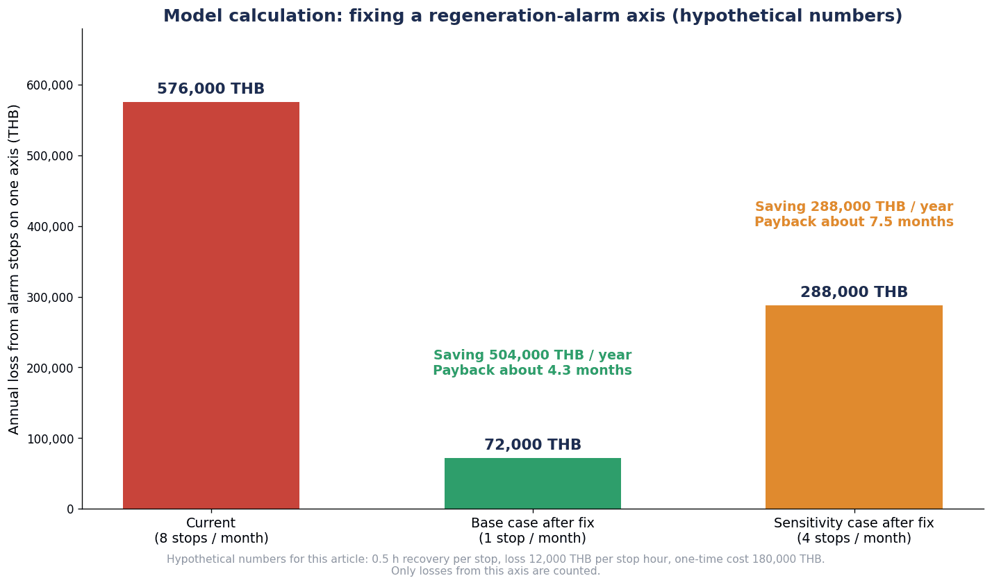
| Base case | Once per month → 1 × 0.5 × 12 = 6 hours/year | 6 × 12,000 = 72,000 THB/year | 576,000 − 72,000 = 504,000 THB/year | 180,000 ÷ 504,000 ≈ 0.36 years (about 4.3 months) |
| Sensitivity (reduced only to 4 times per month) | 4 times per month → 4 × 0.5 × 12 = 24 hours/year | 24 × 12,000 = 288,000 THB/year | 576,000 − 288,000 = 288,000 THB/year | 180,000 ÷ 288,000 ≈ 0.63 years (about 7.5 months) |
How to read the estimate
The payback period varies greatly depending on “how far stoppages are reduced” and “the loss per hour of stoppage.” With the same 180,000 THB countermeasure, the payback is about 4.3 months if stoppages fall to once per month, and about 7.5 months if they fall only to 4 times per month. For a factory that estimates the loss per hour of stoppage below 12,000 THB, the payback period becomes even longer.
This estimate assumes a case where reviewing the regenerative resistor and the motion profile is sufficient within the range of the inertia ratio. If the inertia ratio is far beyond the recommended or allowable range and the motor or gearbox has to be replaced, the initial cost will be larger than in this estimate.
In this article, we recommend recording the number and duration of stoppages and the alarm numbers before taking countermeasures, and checking them against the capacity calculation sheet. Once you know whether the alarm number indicates overvoltage or regenerative overload, and in which part of the operation it occurs, you can judge, based on records rather than assumptions, whether a regenerative resistor is enough or whether the motion profile or even the motor needs to be reviewed. In this article, we take the view that requiring a capacity calculation sheet in the RFP for new equipment makes this kind of rework easier to reduce.
Frequently Asked Questions
What should be calculated first in servo motor selection?
After listing the machine specifications and the motion profile, calculate the load torque and the load moment of inertia converted to the motor shaft. In Yaskawa Electric’s selection procedure, the rotational speed, load torque, load moment of inertia, load moving power and load acceleration power are calculated in that order, and candidates are narrowed down with the four provisional selection conditions. They are then verified with acceleration torque, deceleration torque and RMS torque. The rated output (W) condition is one of the four provisional selection conditions.
Up to what load inertia ratio can a servo motor be used?
There is no single answer. The value differs by manufacturer, series, model, rotational speed and regenerative option conditions. For example, in Panasonic’s MINAS A6, the MSMF 400 W is recommended at 30 times or less and the MHMF 1.0 kW at 5 times or less. In Yaskawa Electric’s Σ-7, the SGM7J-02A is allowable at 15 times (25 times with an external regenerative resistor and an external dynamic brake resistor). Check the values and notes in the catalog of the model to be adopted, and confirm with the manufacturer if the value is exceeded. When comparing candidates, compare by the absolute value of allowable load inertia rather than by the ratio.
How is RMS torque calculated?
Square the torque of each section (acceleration, constant speed, deceleration), multiply by its time and add them up, divide by the time of one cycle including the dwell time, and take the square root. In Yaskawa Electric’s calculation example, Trms = √((TP²·ta + TL²·tc + TS²·td) / t), which is about 0.483 N·m. The 1.5 s in the denominator includes the 0.3 s dwell. On axes that need torque while stopped, such as vertical axes, the holding torque during the dwell also needs to be considered.
When is a regenerative resistor needed?
When the energy returned during deceleration to a stop or lowering of a vertical axis exceeds the processing capacity of the amplifier. For small-capacity amplifiers without a built-in regenerative resistor, Yaskawa Electric presents a simplified calculation that compares the rotational energy obtained with ES = J·nM² / 182 against the energy the amplifier can process. Panasonic explains that the allowable regenerative brake frequency becomes 1/(m+1) depending on the inertia ratio. Yaskawa Electric explains that continuous regeneration, such as tension-controlled feeding, cannot be handled by the amplifier’s resistor-based regenerative processing, and that a power regeneration converter or similar equipment needs to be considered.
Why is a gearbox added to a servo motor?
The main reasons are to match speed and torque and to lower the inertia ratio. In Yaskawa Electric’s formulas, the load inertia converted to the motor shaft is divided by the square of the reduction ratio. Siemens also lists adjustment of the inertia ratio as a purpose of geared motors. However, raising the reduction ratio increases the motor rotational speed, and backlash and mounting orientation are added as specification items. Also consider the option of changing the inertia class on the motor side.
What is the price of a servo motor?
Published figures are of mixed types and are difficult to use as a market rate. In the standard prices (excluding tax) in Mitsubishi Electric’s catalog (February 2025 edition), the HK-KT43W (0.4 kW) is 131,000 yen without a brake and 190,000 yen with a brake. On MonotaRO, Yaskawa Electric’s SGM7J-04AFA21 (0.4 kW, without brake) was listed at 49,980 yen excluding tax and 54,978 yen including tax (viewed October 16, 2026, shown as out of stock). Standard prices and selling prices are different types, and the online price is for the motor alone, without the amplifier and other components. Public prices within Thailand could not be confirmed. We recommend obtaining quotations for a matched configuration.
If a drive has STO, are safety fences and safety circuits unnecessary?
It cannot be said that they are unnecessary. STO is a function that removes motor torque, and Mitsubishi Electric and Fuji Electric explain that it corresponds to stop category 0 or results in free-run. The achievable safety level changes with the model and the wiring and diagnosis conditions. In Panasonic’s example, the level is either SIL3, PLe or SIL2, PLd, depending on whether diagnosis by EDM is used. Preventing a vertical axis from dropping is considered separately with a holding brake or similar. Whether fences, doors, light curtains and safety circuits are needed, and how they are combined, is designed after determining the required safety level through risk assessment.
Summary
- In this article, we take the view that servo motor selection is not decided by the rated output (W) column alone. Even in Yaskawa Electric’s provisional selection, output is one of four conditions
- Select by three items: (1) load inertia ratio, (2) peak torque and RMS torque calculated from the motion profile, and (3) regenerative energy with the amplifier and regenerative resistor
- The upper limit of the inertia ratio changes with the manufacturer, model, rotational speed, regenerative option and dynamic brake conditions. Compare candidates by the absolute value of allowable load inertia and its conditions
- (1) and (3) are connected. According to Panasonic, the allowable regenerative brake frequency becomes 1/(m+1), and Yaskawa Electric explains that A.400 or A.320 can occur when the inertia ratio is exceeded
- RMS torque is averaged over the whole cycle including the dwell time. On vertical axes, also consider the holding torque during the dwell
- Yaskawa Electric’s ratings assume 40°C ambient and heat sink mounting. Include mounting conditions and ambient temperature in the selection conditions, and check the temperature on the actual machine
- Our view is that (4) the gearbox, holding brake, encoder, communication, STO, mounting conditions and ambient temperature should be written into the RFP and verified at FAT/SAT
- STO is a function that removes torque, and the safety level is determined by the model and the wiring and diagnosis conditions. Holding of vertical axes is considered separately
- In the estimate with hypothetical figures, the payback was about 4.3 months in the base case and about 7.5 months if stoppages fell only to 4 times per month. It varies greatly depending on how far stoppages are reduced
TOMAS TECH can help from the early stages, such as organizing machine specifications and motion profiles, reviewing capacity calculation sheets and sorting out RFP requirements. If you are considering selecting or reviewing servo motors, please feel free to reach out through our contact page.
References
- AC SERVO DRIVES Σ-7 SERIES (Yaskawa Electric, PDF, 2016)
- Σ-7-Series AC Servo Drive Rotary Servomotor Product Manual (Yaskawa Electric, PDF)
- Sigma-7 400 V Product Catalog (Yaskawa Electric Σ-7 document for Europe, PDF, 2018)
- Mitsubishi Electric AC Servo System MELSERVO-J5 (Mitsubishi Electric, PDF, 2025)
- AC Servo Motors and Amplifiers MINAS A6 Family (Panasonic Industry, PDF, 2026)
- Servo System ALPHA7 (Fuji Electric, PDF, 2021)
- AM8500 Synchronous servomotors with increased rotor moment of inertia (Beckhoff)
- Servomotor 1FK2 nu med planetväxlar och i nya utföranden (Siemens, PDF, 2021)
- Studio 5000 Logix Designer 38.00 Help: Load (Rockwell Automation)
- IEC 61800-5-2:2016 (IEC Webstore)
- Σ-7 Series Rotary Servomotor, Medium Inertia, SGM7J, Yaskawa Electric (MonotaRO)
- PR No.117/2569 1H 2026 Investment (Thailand Board of Investment, PDF)
- PR No.124/2569 BOI at 60 (Thailand Board of Investment, PDF)
- Five Million Robots now Operate in Factories Globally (IFR)
- China Installs 59 Percent of World’s Industrial Robots (IFR, PDF)


