


The drawing from your machine builder says only “Coupling, Maker X, Type Y.” The calculation sheet shows a pass based on “permissible torque > motor peak torque × service factor.” Yet closing out shaft coupling selection on that single line carries real risk. The same term, “service factor,” means different things at different makers: some apply it to the motor’s peak torque, some to the load-side torque, and some say no correction is needed at all. For temperature correction, some makers even apply the factor in the opposite direction.
This article makes one argument: selecting a coupling (shaft coupling) does not end with “Is the catalog’s permissible torque high enough?” Service factors are defined differently by each maker, the shaft-hub connection (set screw or clamp) can slip before the coupling body itself reaches its limit, and higher torsional stiffness is not always better. That is why the buyer should write the following four points into the RFP (request for proposal/quotation) and the FAT/SAT.
- Require the calculation sheet to state “which maker’s table the factor comes from, and what it was applied to”
- Require confirmation of both the permissible torque and the slip torque of the shaft-hub connection
- Allocate misalignment not by the stand-alone allowable values, but by a design target that allows for combined misalignment and changes during operation
- Judge torsional stiffness not on the coupling alone, but on the whole system including the screw or gearbox, together with servo tuning
The rest of this article is written for production engineers, machine designers, maintenance staff and buyers who design, order and maintain automated machines, inspection equipment and conveying equipment at Japanese-affiliated plants in Thailand (and ASEAN). It covers coupling types, the 7 selection steps, torque and service factors, shaft-hub connections, misalignment, torsional stiffness and resonance, speed and temperature, common failures, the RFP, FAT/SAT, and procurement in Thailand, in that order. Ball screws for feed drives are covered in “Ball Screw Selection for Thailand: RFP and FAT/SAT Guide” and linear guidance in “Linear Guide Selection: Life Calculation, Preload, Accuracy and RFP for Thai Factories“, so this article focuses on “the coupling itself that connects the motor shaft to the driven shaft.” The model calculations in this article are not design values for any specific machine; they are examples to show the structure and sensitivity of the calculation.
Why “Rated Torque Only” Is Risky in Coupling Selection
The same “service factor” means different things at different makers
Almost every maker uses some kind of factor when selecting coupling torque. What the factor is applied to, however, is not consistent.
- Misumi says that, when connecting to servo motors or stepper motors, the coupling should be chosen so that “motor peak torque × service factor = corrected torque” does not exceed the permissible torque.
- Nabeya Bi-tech (NBK) defines its normal torque as “a value that already accounts for load fluctuation during operation” and explains that no correction is needed (Oldham types are treated separately).
- KTR multiplies the driving-side peak torque by the inertia ratio, a temperature factor and a service factor, and compares the result with the coupling’s rated torque.
- R+W (bellows type) gives a simplified formula of 1.5 times peak torque, and a detailed formula using the inertia ratio and a factor.
In other words, if you compare a figure calculated with one maker’s factor against another maker’s catalog value, you may end up comparing things based on different conditions. A later section shows an example in which, with the same inputs, the required torque varies over a range of about 1.8 times depending on the calculation approach.
Even with enough torque, the shaft-hub connection can slip first
The other pitfall is the connection between coupling and shaft. Misumi says that even when the load torque is below the permissible torque, the shaft and coupling can slip if the set screws or clamp bolts are not tightened enough, and calls this the “shaft slip torque.” KTR also writes that the shaft-hub connection must be verified by the customer. If you sign off based only on the permissible torque of the coupling body, the check on the connection side gets skipped.
Upcoming trade shows (planned)
JIMTOF2026 is scheduled for October 26–31, 2026, at Tokyo Big Sight. According to the organizer’s announcement on September 28, 1,134 companies (including direct, co-exhibitors and internal exhibitors; 4,422 booths) from 22 countries and regions are scheduled to exhibit, and Miki Pulley has announced on its website that it plans to exhibit. In Thailand, METALEX 2026 is scheduled for November 18–21 at BITEC (Bangkok). Having this article’s selection criteria at hand before you see the hardware at a show should make it easier to ask the booth staff the right questions.
What Is a Coupling (Shaft Coupling)? Roles and Main Types
Two roles: transmit torque and absorb misalignment
A coupling connects two shafts that are supported by separate bearings, such as a motor shaft and a ball screw shaft or a gearbox input shaft. It has two main roles.
- Torque transmission: transmitting motor torque to the driven shaft without slip or play
- Misalignment absorption: absorbing parallel offset (radial misalignment), angular misalignment and axial displacement (end play) between the two shafts through deformation of a flexible element
These two roles are, to some degree, a trade-off. Miki Pulley explains that rigid couplings cannot absorb mounting errors but are inexpensive, and because they generate large reaction forces they are suited to low speeds. Conversely, flexible couplings absorb mounting errors through deformation of the flexible element, but Miki Pulley also notes that this deformation generates reaction forces on bearings and other components.
Backlash and torsional lag
In positioning applications, it helps to distinguish two kinds of “delay.” In Miki Pulley’s explanation, backlash is play caused by things such as the clearance between key and shaft, while torsional lag is the delay between the rubber being compressed and torque being transmitted. They are different things, but Miki Pulley says “neither can be used in applications that require positioning accuracy.” That does not mean every type using rubber or resin is unusable for servo axes, however. There are also jaw couplings such as KTR’s ROTEX GS, in which the spider is fitted into the hubs under preload to achieve zero backlash.
Comparison of main types
The table below summarizes the characteristics of the main types within the scope of the maker documents referenced in this article. Always read the figures as examples tied to a specific maker and series.
| Type | Characteristics (within the scope of the sources) | Suitable applications / notes |
|---|---|---|
| Rigid | Cannot absorb mounting errors but inexpensive; generates large reaction forces (Miki Pulley). Misumi lists it as one of the high-torsional-stiffness types | Suited to low speeds (Miki Pulley). Assumes accurate shaft alignment |
| Jaw (general industrial) | Lovejoy (Timken) L type lets you choose the spider material. For NBR and urethane, allowable misalignment is 1° angular and 0.015 in parallel | General industrial use such as pumps and fans. Lovejoy does not recommend urethane or Hytrel for applications with frequent starts and stops |
| Jaw (servo, preloaded) | KTR ROTEX GS: the spider’s cams are fitted under preload for zero backlash, vibration damping, stiffness adjustable by spider hardness, electrical insulation (KTR’s description) | For positioning. State “zero backlash (preloaded type)” explicitly in the specification |
| Disc (single) | Short overall length and high stiffness. By design, it can hardly tolerate radial misalignment (Misumi). Allowable radial misalignment of Miki Pulley SFF-060SS-60N is 0.02 mm | Use only when space is truly lacking, with careful attention to alignment (Misumi) |
| Disc (double) | Can absorb radial and angular misalignment but has a longer overall length (Misumi). Within the same series, torsional stiffness is about half that of the single type (Miki Pulley SFF, KTR RADEX-NC) | Misumi lists disc types for high-precision servo positioning and reversing operation (without distinguishing single from double) |
| Bellows | R+W claims it offers “generally the highest torsional stiffness among commercially available flexible shaft couplings.” Restoring forces on adjacent shafts and bearings are relatively small (R+W) | R+W warns that replacing another type with a bellows coupling without considering parallel misalignment can lead to failure |
| Slit | Misumi lists it alongside disc types as a zero-backlash type | Consider for high-precision servo positioning and reversing operation (Misumi) |
| Integrated vibration-damping rubber | Misumi lists it as one of the high-torsional-stiffness types and explains that it can shorten servo tuning time | Also listed as a vibration countermeasure for stepper motors (Misumi) |
| Universal joint | Allowable angular misalignment of 30° in Misumi’s description | For very large angular misalignment (Misumi) |
The purpose of this table is not to rank the types, but to confirm that “each type handles different kinds of misalignment and has different stiffness.” Misumi’s type guide summarizes it this way: for high torsional stiffness, consider disc, integrated vibration-damping rubber or rigid types; for servo axes with high-precision positioning or reversing, consider zero-backlash disc or slit types. Miki Pulley explains that rubber and resin, with good vibration absorption, suit engine drives, while metal couplings with high torsional stiffness suit precision machinery such as servo motors.
Think of jaw couplings as “two different kinds”
Jaw couplings are a type that is particularly easy to confuse. A general industrial jaw coupling such as Lovejoy’s L type and a preloaded servo jaw coupling such as KTR’s ROTEX GS may look similar, but their design philosophies differ. The former is for general industrial use such as pumps and fans; the latter is for zero-backlash positioning. If a drawing or RFP says only “jaw type,” there is room for a general industrial jaw coupling to be fitted at replacement time. For servo axes, it is safer to state “zero backlash (preloaded type)” explicitly.
About standards
You may see ISO 14691 cited as a coupling standard, but according to ISO’s public page, ISO 14691:2008 is a standard for flexible couplings used in general-purpose applications in the petroleum, petrochemical and natural gas industries; rigid couplings are treated as out of scope, and it does not define type-selection criteria by application. Note that it is not a standard for selecting couplings for servo axes on factory automation equipment. KTR says it selects servo couplings based on DIN 740 part 2 using its own specific factors, and R+W also writes that bellows sizing generally follows DIN 740, but the factor values are given in each maker’s own documents.
The 7 Steps of Coupling Selection
The following is the selection sequence, assuming a servo axis. Combining the common parts of each maker’s procedure gives the following 7 steps.
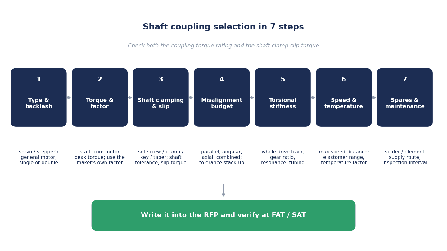
| Step | What to decide | Main checkpoints |
|---|---|---|
| 1. Application and type | Whether zero backlash is required; servo, stepper or general-purpose motor; single or double | Positioning or continuous rotation? Is the structure able to guarantee alignment? |
| 2. Torque | Start from the motor’s maximum (peak) torque, then correct with the chosen maker’s factors and the inertia ratio | Source of the factor (maker and table name), and what it was applied to |
| 3. Shaft-hub connection | Set screw, clamp, key or taper; shaft tolerance; shaft insertion depth; whether the shaft has a D-cut | Both the permissible torque and the slip torque of the shaft-hub connection |
| 4. Misalignment | Allowable radial, angular and axial values, and how combined misalignment is handled | Allocate tolerances by a design target, not stand-alone allowable values |
| 5. Torsional stiffness and inertia | Stiffness of the whole system, reduction ratio, resonance, servo tuning | Do not judge on the coupling’s stiffness alone |
| 6. Speed and temperature | Maximum speed and balance, temperature range of the elastomer, temperature correction | Direction of temperature correction (allowable side or load side) |
| 7. RFP and FAT/SAT | Specification items, acceptance tests, spare parts | Records of calculation sheet, tightening torque and alignment |
The key point is that steps 1 to 7 are not a one-way street. For example, if step 5 reveals insufficient stiffness, you go back to the type in step 1; if step 4 shows that a single disc coupling cannot guarantee alignment, you switch to a double, and as a result stiffness drops in step 5. You move back and forth like this. For choosing the motor and drive themselves, see also “Servo Control vs Inverter Control 2026 | 4 Boundaries That Decide the Choice“.
Servo Motor Couplings: Torque and Service Factors
The starting point is the motor’s peak torque
For couplings used with servo motors, Misumi, Miki Pulley, KTR and R+W share the approach of using the motor’s maximum (peak) torque as the starting point. Miki Pulley explains that servo motors produce a peak torque of about 3 times or more their continuous torque and start and stop frequently, so the coupling must withstand that peak torque (the “about 3 times” is Miki Pulley’s general explanation; check the individual motor in the motor catalog). Miki Pulley states its metal plate-spring couplings in terms of “permissible torque,” and its couplings for general-purpose motors and engines in terms of “rated torque” and “maximum torque.”
How each maker defines its service factor
| Maker | What the factor is applied to | Example factor values (as each maker defines them) |
|---|---|---|
| Misumi | Motor peak torque × service factor = corrected torque ≤ permissible torque (shaft slip torque) | Reference value of 2.0 for typical servo use. Varies widely from 1 to 5 depending on operating environment and type. For general-purpose motors, 1 to 5 times the load torque |
| Nabeya Bi-tech | The smaller of normal torque and slip torque ≥ load torque in continuous operation | Normal torque already includes load fluctuation, so no correction is needed (Oldham types treated separately). For rubber and resin products, temperature correction is applied to the allowable side |
| Miki Pulley | Whether the metal plate-spring type’s permissible torque withstands the servo’s peak torque | For general-purpose motors and engines, rated torque and maximum torque (about 2 times rated) |
| KTR (ROTEX GS) | Driving-side peak × inertia ratio × temperature factor St × service factor SB ≤ TKN | SB: 2.5 to 4.0 for ball screw and timing belt positioning; St (92/98 ShA): 1.2 at 40 °C or below |
| KTR (TOOLFLEX, RADEX-NC) | Same as above | SB: 1.5 to 2.0 for machine tool servo drives. St is about 1.0 |
| R+W (bellows) | Simplified formula 1.5 × peak; acceleration torque formula peak × S_A × inertia ratio | S_A: 1 for uniform, 2 for non-uniform, 3 to 4 for highly dynamic or reversing |
| Lovejoy (general industrial jaw) | Nominal torque × application factor | 1.00 to 2.50 (e.g., 1.25 for a rotary pump with a standard-torque electric motor) |
What this table shows is that, before the “numbers,” the thing the factor is “applied to” differs. Misumi’s 2.0 is applied to the motor’s peak torque, while KTR’s 4 is applied, together with a temperature factor, to a peak torque that has already been scaled down by the inertia ratio. Nabeya Bi-tech’s normal torque is a value that already incorporates fluctuation in the first place. It is not a question of which factor is right; each factor is meant to be used together with that maker’s own definition of permissible torque.
Model calculation A: on the same axis, the required torque changes with whose formula you use
Here we apply each maker’s formula to the same inputs. The inputs are borrowed from the ball screw calculation example in KTR’s catalog. These are not design values for any specific machine; they are an example to show the structure and sensitivity of the calculation.
- Motor (driving-side) peak torque T_AS: 144 Nm
- Driving-side inertia J_A: 0.011317 kgm² (motor 0.0108 + coupling half 0.000517)
- Load-side inertia J_L: 0.006917 kgm² (screw 0.0038 + slide and workpiece 0.0026 + coupling half 0.000517; slide and workpiece 1,030 kg, lead 10 mm)
- Inertia ratio MA = J_L/(J_A + J_L) = 0.006917/0.018234 ≈ 0.379
- Ambient temperature 40 °C, 15 starts per minute
| Calculation approach (maker) | Formula | Approximate required torque |
|---|---|---|
| Misumi (motor peak torque × service factor; servo reference value 2.0) | 144 × 2.0 | 288 Nm |
| KTR (ROTEX GS; peak × inertia ratio × temperature factor St 1.2 × service factor SB 4) | 144 × 0.379 × 1.2 × 4 | About 262 Nm (261.9 Nm in KTR’s calculation example) |
| R+W (simplified formula 1.5 × peak) | 1.5 × 144 | 216 Nm |
| R+W (acceleration torque formula, S_A 4) | 144 × 4 × 0.379 | About 218 Nm |
| R+W (acceleration torque formula, S_A 3) | 144 × 3 × 0.379 | About 164 Nm |
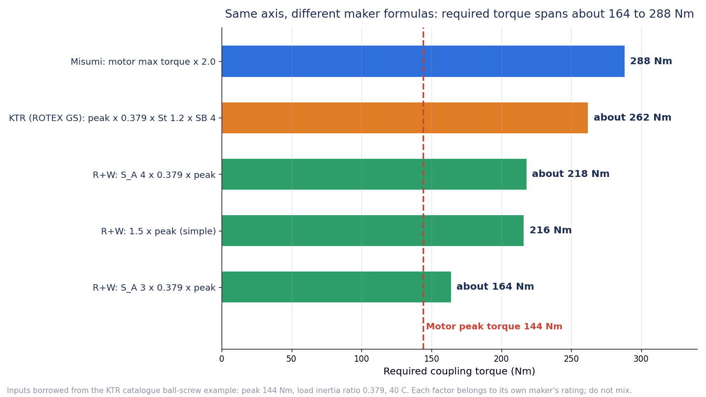
On the same axis, the result ranges from about 164 to 288 Nm, a spread of about 1.8 times. To repeat, this is not about which one is correct. Misumi’s 288 Nm is a figure to compare against Misumi’s permissible torque, and KTR’s roughly 262 Nm is a figure to compare against KTR’s TKN. You must not compare a figure calculated with one maker’s factor against another maker’s catalog value.
In KTR’s calculation example, ROTEX GS 38 (98 ShA, clamping ring hub 6.0 light, TKN 325 Nm) is selected for these conditions and judged “acceptable” because 261.9 Nm ≤ 325 Nm. The service factor SB 4 is the value KTR chose for a “high stiffness requirement,” and is the upper end of the 2.5 to 4.0 range for positioning applications. In the same example, KTR also confirms that the transmittable torque of the shaft-hub connection (Ø30, H7/k6: 656 Nm) is greater than the motor’s peak torque of 144 Nm. The calculation example itself shows that the torque check has two parts: the coupling body and the shaft-hub connection.
KTR’s service factors also include values that change greatly with the gear reduction ratio (8.0 for i of 3 up to 5, 5.0 for i above 5 up to 7, and 3.0 for i above 7). When a coupling is used together with a gearbox, check this together with the gearbox selection. Gearbox selection is covered in “Gearbox Reducer Selection — 3 Types and Thai Plant Costing“.
Temperature correction runs in “opposite directions”
Temperature correction is also defined in opposite directions by different makers.
- Nabeya Bi-tech, for rubber and resin products, applies a factor below 1 to the normal torque and maximum torque (the allowable side) when the ambient temperature exceeds 30 °C: 0.80 for 30 to 40 °C, 0.70 for 40 to 60 °C, and 0.55 for 60 to 120 °C (some products, such as all-metal products, need no temperature correction).
- KTR (ROTEX GS, 92/98 ShA spiders) applies a temperature factor St of 1 or more to the load side. Excerpting from the table: 1.0 at 30 °C or below, 1.2 at 40 °C or below, 1.4 at 60 °C or below, 1.8 at 80 °C or below, 2.2 at 90 °C or below, and so on, with separate values for the temperature bands in between.
For example, at an ambient temperature of 55 °C, Nabeya Bi-tech multiplies the permissible torque side by 0.70, while KTR multiplies the load side by 1.4. Both mean the same thing in the sense of “increasing the margin when the temperature is high,” but if both were applied at the same time, the result would be a double correction of 1.4 ÷ 0.70 = 2.0 times. Conversely, if you calculate the load torque using the procedure of a maker that corrects on the allowable side (no correction on the load side) and then compare it directly with the catalog value of a maker that corrects on the load side, the temperature correction can end up in neither place and be missed entirely. Require the calculation sheet to state which side the temperature factor was applied to.
Shaft-Hub Connections: Set Screw, Clamp, Key and Taper
Comparison of connection methods
| Connection method | Characteristics (within the scope of the sources) | Notes |
|---|---|---|
| Set screw | Low cost and the most common (Misumi). Miki Pulley positions it for low torque and small diameters (up to about φ20), and explains that because it does not readily deliver sufficient torque, a D-cut is used to compensate | The screw tip bears on the shaft and may damage it or make removal difficult (Misumi) |
| Clamp | Does not damage the shaft and is easy to mount and remove (Misumi). Miki Pulley positions the single clamp for reversing servo applications, with shaft diameters usually 35 mm or less, and the double clamp up to about 40 mm | Slip torque changes with shaft tolerance (see below). Take care with D-cut shafts |
| Key | Relatively high torque; used together with set screws or clamps (Misumi) | Clearance can produce play under load (Miki Pulley) |
| Taper (surface pressure) | Secure and high torque; suited to machine tool spindles (Misumi). Miki Pulley explains that it has high holding force and can handle 20,000 rpm or more | Follow the specifications for each type and size |
Misumi states that “any type has no problem with fastening force within the permissible torque,” while stressing that insufficient tightening leads to slip. On servo axes with frequent reversing, using a key means the clearance becomes play, which directly affects positioning accuracy.
Shaft tolerance and slip torque: the same hub can give different values
The transmittable torque of a clamp connection changes with shaft diameter and shaft tolerance. The table in KTR’s ROTEX GS operating instructions (clamping ring hub 6.0 light) shows the following.
| KTR ROTEX GS (clamping ring hub 6.0 light) | Shaft tolerance k6 | Shaft tolerance h6 | Ratio of h6 to k6 |
|---|---|---|---|
| Size 14, Ø14 | 36.2 Nm | 24.7 Nm | About 0.68 (about 30% lower) |
| Size 38, Ø30 | 656 Nm | 626 Nm | About 0.95 (about 5% lower) |
Even with the same hub, the slip torque falls as the shaft tolerance moves toward the clearance side, and in this example the difference is larger at the smaller diameter. KTR states that the larger the fit clearance, and with hollow shafts, the lower the friction torque, and that hollow shafts require a strength calculation. At small diameters, the value on the connection side can be lower than the rating of the coupling body, in which case the connection becomes the limiting factor.
Shaft tolerance specifications also differ by maker. Misumi gives the recommended shaft tolerance as “h6, h7, etc.,” while KTR lists both k6 and h6 (the motor shaft in its calculation example is 32 k6). mayr, in the ROBA-DS operating instructions, specifies H7/k6 for clamping hubs and H7/g6 for split clamping hubs. R+W explains that the bores of precision couplings are mostly ISO H7, while motor and gearbox shafts are made at zero or slightly minus, resulting in a clearance fit. Miki Pulley recommends a clearance fit for its own products. It is important to check which tolerance the slip torque was calculated for against the actual tolerance of the motor shaft.
Keyways also need care. Miki Pulley notes that the keyway width tolerance for JIS parallel keys comes in P9 (precision grade) and Js9 (normal grade), but its standard bore machining is H9, and warns not to confuse key widths and tolerances, which differ between the new JIS, old JIS and new-standard motors. KTR provides keyways to DIN 6885 sheet 1, JS9.
Misumi’s “shaft slip torque” and the order of selection
Misumi writes that when the shaft slip torque is lower than the permissible torque, the coupling should be selected so that the load torque is at or below the shaft slip torque. Nabeya Bi-tech likewise says the size should be chosen so that “the smaller of normal torque and slip torque” is at or above the load torque in continuous operation. Both follow the same idea: judge by whichever is weaker, the coupling body or the connection.
Shaft insertion depth and D-cuts
Misumi’s troubleshooting guide says that the shaft insertion depth is based on the hub length; too short leads to slip or damage at the clamp, and too long leads to damage from internal interference. It also cautions that clamp types should in principle be used on round shafts, and that on D-cut shafts, depending on where the D-cut face is, excessive load during tightening can cause damage, so the D-cut face should not lie across the slit. Whether the motor shaft has a D-cut or is round is an item worth checking at both the RFP and acceptance stages.
Coupling Misalignment: Reading Allowable Values and Allocating Tolerances
Radial, angular and axial
There are three kinds of misalignment: radial (parallel offset), angular and axial. Misumi calls them eccentricity, angular misalignment and end play, while KTR, mayr and R+W use radial, angular and axial.
Catalog allowable values are for “a single type occurring alone”
What is most often misread here is the meaning of the catalog allowable values.
- Misumi: the allowable values in the dimension and performance tables apply when only one of radial misalignment, angular misalignment or end play occurs alone. When two or more occur together, each allowable value is halved (1/2). In addition, misalignment also arises during operation from vibration, thermal expansion and bearing wear, so Misumi recommends staying at or below 1/3 of the allowable value.
- KTR (ROTEX GS): the displacement values in the table are general standard values for loads up to TKN at an ambient temperature of +30 °C, and are maximum values that must not occur simultaneously. When radial and angular displacement occur at the same time, they are prorated so that the total is 100% or less, for example 30% radial + 70% angular.
- mayr (ROBA-DS, disc pack type): for the double type (Type 951), the allowable values in the table must not all reach their maximum at the same time, and the sum of the actual values as percentages must be 100% or less. In the size 10 example, with 0.36 mm axial (40% of the 0.9 mm maximum) and 0.3° angular (30% of the 1° maximum), radial misalignment is limited to 30% of the 0.2 mm maximum, i.e. 0.06 mm (40% + 30% + 30% = 100%).
For KTR’s ROTEX GS 24, the allowable values also change with spider hardness. Radial is 0.14 mm with 92 ShA, 0.10 mm with 98 ShA and 0.07 mm with 64 ShD, and angular is 1.0°, 0.9° and 0.8° respectively; the harder the spider, the smaller the allowable displacement. In other words, choosing a harder spider to raise stiffness makes the alignment requirement tighter.
An example where tolerance stack-up exceeds the allowable value
As a troubleshooting case, Misumi describes a machine using an SCPW28-6-6 with an allowable radial misalignment of 0.15 mm, where the motor height was 40±0.1 mm and the ball screw height was 40±0.07 mm, so the maximum radial misalignment reached 0.17 mm and exceeded the allowable value (0.1 + 0.07 = 0.17 mm > 0.15 mm). The cause was that the tolerance had not been communicated to the person drawing the bracket.
What this case shows is that the allowable radial misalignment is not a value where “anything is fine as long as the assembled result is below it,” but a budget to be allocated at the design stage to the tolerances of the brackets and base. Following Misumi’s recommendation (1/3 of the allowable value or less), an allowable value of 0.15 mm gives a design target of 0.05 mm or less, which is then divided between the mounting-height tolerances on the motor side and the screw side. Note that the 1/2 for combined misalignment and the 1/3 allowing for changes during operation are written as separate cautions in Misumi’s explanation, and this article does not use a value obtained by multiplying the two together.
Single versus double
For disc couplings, the ability to absorb misalignment and the stiffness differ greatly between single and double types.
| Example (maker, series, size) | Allowable radial misalignment | Torsional stiffness |
|---|---|---|
| Miki Pulley SFF-060SS-60N (single, rated 60 N·m) | 0.02 mm | 104,000 N·m/rad |
| Miki Pulley SFF-060DS-60N (double, rated 60 N·m) | 0.20 mm | 52,000 N·m/rad |
| Miki Pulley SFF-100SS-450N (single, rated 450 N·m) | 0.02 mm | 740,000 N·m/rad |
| Miki Pulley SFF-100DS-450N (double) | 0.38 mm | 370,000 N·m/rad |
| KTR RADEX-NC 26 EK (single) | Cannot absorb radial misalignment (shown as “—” in the table) | 84,000 Nm/rad |
| KTR RADEX-NC 26 DK (double) | 0.33 mm | 42,000 Nm/rad |
In Miki Pulley’s published SFF values, the double type’s allowable radial misalignment is more than 10 times that of the single type, but its torsional stiffness is half (Miki Pulley notes in the table that the torsional spring constant is the value for the element alone). For KTR’s RADEX-NC 26 as well, only the double DK can absorb radial displacement, and its stiffness is half that of the EK. If you choose a single type, either make sure alignment is achieved structurally, for example by joining via a spigot (centering pilot), or specify the alignment procedure and measurement method together with it. R+W also says that for equipment joined by a spigot, the spigot alone maintains sufficient alignment.
Misalignment becomes bearing reaction force
Misalignment is not just a coupling problem. Miki Pulley explains that the deformation of a flexible coupling generates reaction forces on bearings and other components, and Misumi says that runout of the driven shaft caused by the coupling is mainly due to shaft reaction forces from insufficient alignment. mayr also writes that accurate alignment reduces reaction forces and extends the life of both the coupling and the bearings. Because it also affects the life of the ball screw support bearings and the motor bearings, treat alignment not as “fine as long as the coupling doesn’t break,” but as a matter of life for the whole drive train. Miki Pulley also says that at an angular misalignment of 1° or less, the angular velocity fluctuation is about 1%, which is generally not a problem.
Coupling Torsional Stiffness and Resonance
Higher stiffness is not always better
If torsional stiffness is too low, positioning response can lag or resonance can occur. Misumi says that the larger the static torsional spring constant, the higher the responsiveness, and that on servo axes low torsional stiffness can cause resonance. On the other hand, KTR writes in a white paper that, although it is intuitive to think high stiffness is good, this is not necessarily so, and that a drive train with extremely high torsional stiffness can cause vibration problems in the control loop (suppressing them with electrical filters reduces responsiveness). This is KTR’s claim. KTR also states that the stiffness of the whole drive train is determined by its softest element, and that a servo coupling must not be less stiff than the driven unit.
Model calculation B: differences in coupling stiffness alone shrink when viewed as a whole system
Using the same J_A and J_L as in calculation A, we calculate the natural frequency with the two-mass-system formula given in R+W’s documentation.
f = (1/2π)·√(C·(J_A + J_L)/(J_A·J_L))
We compare the case using only the coupling stiffness C with the case adding the stiffness of the screw, nut and bearings. For the screw-side stiffness, we use the value converted to the drive shaft from KTR’s calculation example, 361 Nm/rad, and combine it as springs in series using KTR’s method (1/C_total = 1/C_coupling + 1/C_linear).
| Coupling (KTR, static torsional stiffness) | f calculated with the coupling alone | Total stiffness including the screw side | f calculated with total stiffness |
|---|---|---|---|
| ROTEX GS 28 (jaw, 98 ShA) 6,410 Nm/rad | About 194.5 Hz | About 342 Nm/rad | About 44.9 Hz |
| ROTEX GS 38 (jaw, 98 ShA) 11,800 Nm/rad | About 263.9 Hz | About 350 Nm/rad | About 45.5 Hz |
| RADEX-NC 26 DK (disc) 42,000 Nm/rad | About 497.8 Hz | About 358 Nm/rad | About 46.0 Hz |
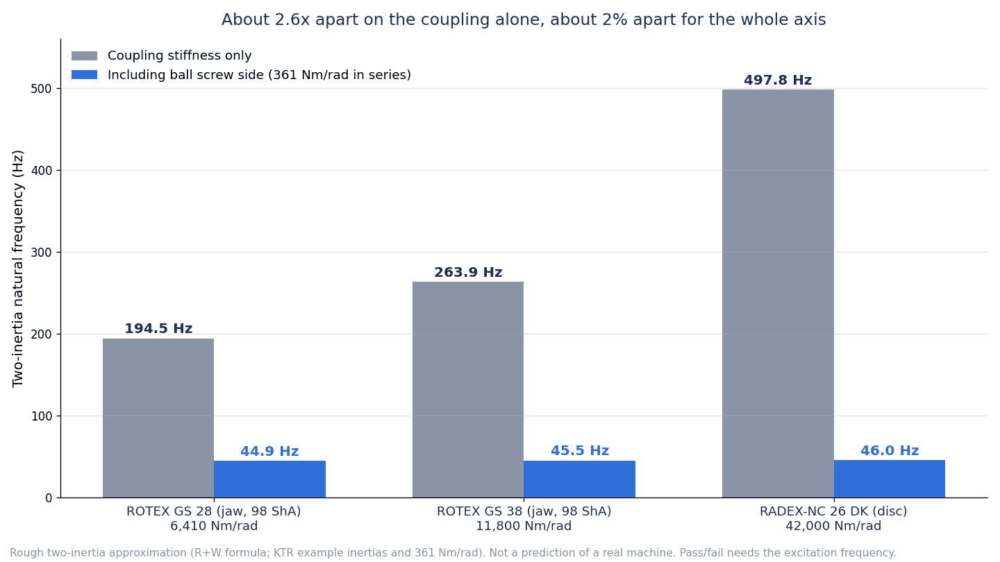
Comparing the couplings alone, the natural frequencies differ by about 2.6 times (497.8 ÷ 194.5). But once the screw-side stiffness is included, about 44.9 Hz and about 46.0 Hz differ by just over 2% (because natural frequency is proportional to the square root of stiffness, the difference comes out smaller than the difference in stiffness). KTR’s calculation example also states that even though the coupling stiffness differs by about 7 times, the difference in total stiffness is limited to 4.7% (342 versus 358 Nm/rad). On this ball screw axis, replacing the coupling with a higher-stiffness one barely moves the machine’s resonance: that is how to read this calculation.
The conclusion depends on the conditions, however. KTR also presents an example with a backlash-free worm gear: at a reduction ratio of i = 3, the drop in total stiffness compared with the gear alone is 64.68% with ROTEX GS 24 (jaw type) versus 14.29% with RADEX-NC 21 EK (disc type), a large difference. In the appendix table, the figures are 20.48% and 2.29% at i = 8, and 6.83% and 0.66% at i = 15. The smaller the reduction ratio, the more the coupling stiffness affects the whole system. From this example, KTR concludes that ROTEX GS is suitable from about i = 8, and that disc or bellows types should be used at small reduction ratios. In the comparison table in KTR’s catalog as well, ROTEX GS is indicated for “feeds with a screw pitch below 40” and “gears with a reduction ratio of 7 or more,” and TOOLFLEX and RADEX-NC for “reduction ratio below 7” and “screw pitch of 40 or more,” as application guidelines.
This calculation always comes with the following assumptions.
- It is a rough two-mass model in which the stiffness of the screw, nut and bearings is converted to the drive shaft and added in series, and the inertia is lumped into two masses; it is not a prediction of the actual machine’s natural frequency.
- The two-mass-system formula comes from R+W’s documentation; the series combination method, the 361 Nm/rad and the inertia values come from KTR’s calculation example. The inertia values include the half-coupling inertia of ROTEX GS 38 and will change slightly with a different coupling.
- R+W states that f_e ≥ 2·f_er (where f_er is the excitation frequency on the driving side) makes it easier to secure sufficient stiffness for smooth, stable operation, but without knowing f_er you cannot judge pass or fail.
- Do not read any meaning into the differences of about 1 Hz in the table.
For reference, using R+W’s torsion angle formula φ = (180/π)·(T_AS/C_T), the torsion angle of the coupling alone at a peak torque of 144 Nm is about 1.29° for ROTEX GS 28 (6,410 Nm/rad) and about 0.20° for RADEX-NC 26 DK (42,000 Nm/rad). These, too, are values for the coupling alone and do not include torsion on the screw side.
What to do when resonance appears
Misumi explains that raising the gain too far causes hunting (overshoot, oscillation), while lowering it too far lengthens settling time. If a disc coupling produces noise or vibration, Misumi says to suppress it on a servo by setting the control system’s mechanical resonance suppression filter to that natural frequency, and on a stepper motor by shifting the rotational speed or absorbing it with a high-damping integrated vibration-damping rubber type. Miki Pulley says that because motors have little rotational unevenness, resonance is rare, but it does occasionally occur with stepper motors.
In short, torsional stiffness is an item to be judged as a pair: “replace the coupling, or suppress it through servo tuning.” How to handle ordering and acceptance including servo tuning is covered in “Servo Control Procurement and FAT/SAT Guide for Thailand Plants in 2026“.
Speed, Temperature and Environment
Maximum speed and balance
The maximum speed in a catalog does not mean “balance is guaranteed at that speed.” Miki Pulley says that maximum speed is determined by material strength (allowable peripheral speed) and generally does not take balance into account. The SFF table notes also state that “maximum speed does not take dynamic balance into account.” The maximum speed of Miki Pulley SFF-060SS-60N is 18,000 min⁻¹, and that of SFF-060DS-60N is 14,000 min⁻¹. R+W explains that its standard bellows products are rated at 10,000 rpm, with the limitation lying in the clamping hub. mayr states that ROBA-DS is within G 6.3 at 1,500 rpm. For high-speed shafts, state in the RFP whether a balance grade is required.
Spider hardness and temperature range
For types using elastomers, the operating temperature and stiffness change with the material and hardness.
| Example (maker, series) | Material and hardness | Temperature range | Typical applications (each maker’s description) |
|---|---|---|---|
| KTR ROTEX GS | 92 ShA (PU) | Continuous −40 to +90 °C / short-term −50 to +120 °C | Measurement and control systems, spindles |
| KTR ROTEX GS | 98 ShA (PU) | Continuous −30 to +90 °C / short-term −40 to +120 °C | Positioning drives, spindles, high loads |
| KTR ROTEX GS | 64 ShD (PU, sizes 42 to 90) | Continuous −20 to +110 °C / short-term −30 to +120 °C | High torsional stiffness, planetary and backlash-free gears |
| KTR ROTEX GS | 64 ShD-H (Hytrel, sizes 7 to 38) | Continuous −50 to +120 °C / short-term −60 to +150 °C | — |
| Lovejoy L type (general industrial) | NBR | −40 to 100 °C | Urethane has 1.5 times the torque capacity of NBR, but lower damping |
| Lovejoy L type (general industrial) | Urethane / Hytrel | −34 to 71 °C / −51 to 121 °C | Not recommended for applications with frequent starts and stops (Lovejoy) |
Miki Pulley explains that it limits the operating temperature of its rubber couplings to −30 to 95 °C, and its aluminum and stainless steel products to a maximum of 120 °C. All of these are values for a specific maker and series and do not necessarily apply directly to other makers’ products. KTR’s spider temperature ranges are used together with the temperature factor St described earlier.
Depending on the machine, heat from the motor and surrounding equipment can raise the temperature around the coupling. Misumi cautions that immediately after stopping, the coupling may be hot from heat from surrounding equipment and should not be touched. Require the calculation sheet to state, as a premise, how the ambient temperature inside the machine was estimated.
Chemicals, oil and ozone
KTR’s failure table states that aggressive liquids and oils, ozone, and excessively high or low temperatures physically change the spider, leading to premature wear and backlash on reversing. On machines exposed to cleaning fluids or cutting oil, consider whether to use a type with elastomers, including whether a cover is fitted.
Common Failures and Their Causes
The failures and causes described in maker documents are organized here so you can look them up by symptom.
| Symptom | Main causes (within the scope of the sources) | Checks and countermeasures |
|---|---|---|
| Breakage, abnormal noise, sharply reduced life | Misalignment exceeds the allowable value (Misumi). Miki Pulley says that even if it does not break immediately, life is shortened, and because it is a rotating part there is a serious risk of parts flying off | Measure alignment; recheck how combined misalignment is handled |
| Broke even though it should have been within the allowable value | Under combined misalignment each allowable value is halved (Misumi) / tolerance stack-up exceeds the allowable value (Misumi’s 0.17 mm > 0.15 mm example) | Recalculate including mounting-height tolerances |
| Slips even when tightened to the specified torque | Motor peak torque exceeds the permissible torque or shaft slip torque / shaft insertion depth is too short (Misumi) | Check shaft slip torque, shaft tolerance and insertion depth |
| Damage at the clamp | D-cut face lies across the slit / insertion depth too short or too long (Misumi) | Position of the D-cut face, insertion depth |
| Bolt loosening or fracture | Below the specified torque, bolts loosen and fracture in shear; above it, excessive stress or seat buckling reduces axial force (Miki Pulley) | Tighten to the specified torque with a torque wrench. For machines with large load fluctuation, use adhesive thread locking or a coupling with one size larger screws (Misumi) |
| Premature spider wear, backlash on reversing | Misalignment (loose foundation bolts, thermal expansion, changes in mounting dimensions); liquids, oil, ozone, temperature (KTR) | Recheck alignment; check the environment |
| Liquefaction of material inside the spider cams | Vibration in the drive train (KTR; may be correctable with a spider of different hardness) | Identify the vibration source; review spider hardness |
| Noise or vibration from disc couplings | Resonance (Misumi); poor alignment, loose connecting screws, fretting corrosion of the disc pack (mayr) | Resonance suppression filter, alignment, check tightening torque |
| Bellows breakage | Replaced another type without considering parallel misalignment (R+W) | Recheck alignment conditions when replacing |
As examples of improper use, KTR lists spiders that are old or have been stored too long, failure to provide the data needed for selection, and failure to calculate the shaft-hub connection. The last two are exactly the items an RFP can prevent. If abnormal noise or vibration appears, Misumi writes that the machine should be stopped immediately and checked for alignment, interference and loose screws. For detecting failures early from vibration trends, see also “Vibration Sensor Machine Diagnostics 2026: Measurable vs Unmeasurable Failures“.
12 Items to Include in a Coupling RFP (Request for Quotation)
These are the coupling-related items worth putting in the specification when requesting quotations from machine builders or system integrators. They are assembled from the makers’ technical documents. Not everything needs to be fixed as a number; the aim is to make the supplier state “on what basis the coupling was selected.”
| No. | Item | What to require | Reason |
|---|---|---|---|
| 1 | Motor conditions | Motor model, maximum and rated torque, inertia | KTR lists failure to provide selection data as an example of improper use |
| 2 | Load-side inertia | Inertia of screw + slide + workpiece | Needed for makers whose formulas use the inertia ratio |
| 3 | Source of factors and calculation sheet | Maker and table name of the factors used, what they were applied to, direction of temperature correction | Definitions differ by maker |
| 4 | Type | Whether zero backlash is required, whether preloaded, single or double | Prevents mix-ups at replacement |
| 5 | Torque check results | Both the permissible torque and the slip torque of the shaft-hub connection | The connection can slip first |
| 6 | Shaft conditions | Shaft diameter and tolerance, key or no key, D-cut or no D-cut | Directly affects slip torque and damage |
| 7 | Misalignment | Allowable values, handling of combined misalignment, design target and tolerance allocation | Catalog values apply to a single type occurring alone |
| 8 | Torsional stiffness | Coupling stiffness and stiffness including the screw or gear side / whether natural frequency was examined | Cannot be judged from the coupling’s stiffness alone |
| 9 | Speed | Maximum speed, whether balancing is required | Catalog maximum speeds may not take balance into account |
| 10 | Temperature and material | Operating temperature range, elastomer material and hardness | Permissible torque and stiffness change with temperature |
| 11 | Tightening | Record of tightening torque values and procedure (stepwise tightening, alternate tightening) | Prevents loosening, slip and damage |
| 12 | Spare parts and inspection | Spare parts such as spiders and elements, supply route, inspection intervals | Procurement risk for replacement parts of imported products |
Items 3 and 5 in particular make a difference at the quotation comparison stage. If Supplier A writes “288 Nm or more with Misumi’s factor of 2.0” and Supplier B writes “262 Nm or more with KTR’s factors,” you can explain why the selected sizes look different even for the same axis. The overall process for ordering special-purpose machines is covered in “Special-Purpose Machine Manufacturing: Evidence-Gated Procurement“.
What to Check at FAT/SAT
These are the coupling-related items worth checking at the factory acceptance test (FAT) and site acceptance test (SAT). The figures for tightening torque and inspection intervals are shown as examples of values for specific makers and series.
| Test item | Method | Criterion | Record |
|---|---|---|---|
| Motor shaft runout | Place a dial gauge on the motor shaft and check runout before mounting (Misumi) | Understood as the baseline for alignment accuracy | Measured runout |
| Alignment | Dial gauge, straightedge, feeler gauge (KTR); straightedge or laser (mayr, R+W) | At or below the design target (do not compare with stand-alone allowable values) | Measured radial, angular and axial values |
| Quick check | With bolts loosened, slide axially and turn rotationally to check for smooth movement (Misumi) | No catching | Done / not done |
| Shaft insertion depth | Check against the dimension specified in the catalog (Misumi) | As specified | Measured value |
| Tightening torque | Tighten to the specified value with a torque wrench; not all at once, but alternating left and right in 2 to 3 passes (Misumi) | Specified value for each model | Model, specified value, person performing |
| Running noise and vibration | Changes in noise and vibration during operation (KTR) | Stop immediately if anything abnormal | Vibration values and observations |
| Behavior after servo tuning | Presence of hunting or resonance; filter settings (Misumi) | No abnormality within specified positioning time and settling | Gain and filter settings |
| Retightening check after initial operation | In the mayr ROBA-DS example, check the tightening torque after 5 to 10 operating hours | Specified value maintained | Date and time checked |
| Safety cover | Fit a protective cover (Misumi, KTR). Do not seal completely; ensure good ventilation (Misumi) | Prevents entanglement and flying parts | Photo of installed condition |
Manage tightening torque with a torque wrench to the specified value for each model. As examples, the clamps of Miki Pulley SFF-SS are 2-M4 at 3.4 N·m for size 040, 2-M5 at 7 N·m for 050, and 2-M6 at 14 N·m for 060 (bore 12 to 22) (per hub side), and the clamping hubs (aluminum) of KTR ROTEX GS are M6 at 10.5 Nm for size 24 and M8 at 25 Nm for size 28. mayr states that the disc pack connecting bolts of ROBA-DS are tightened to the table value in three stages: 30% → 60% → 100%. Because the values differ by model, write “the specified value in the operating instructions” in the specification, and keep the model and specified value as a pair in the acceptance record.
KTR requires that, before start-up, the hub set screws’ tightening, the alignment and the distance dimension be inspected and adjusted, and that all screw connections be checked at the specified torque. At SAT, the basic approach is to re-measure, using the same method as at FAT, whether transport and installation have disturbed the alignment.
Handover to the maintenance plan
Each maker also gives instructions on inspection intervals. For mayr ROBA-DS: a check before initial operation, a tightening torque check after 5 to 10 operating hours, an inspection after 1,000 hours (after 3 months at the latest), and, if there are no abnormalities, every 4,000 hours thereafter (12 months at most), shortened under severe conditions. For KTR ROTEX GS: a visual inspection at least once a year (especially of the spider), and re-inspection and readjustment of alignment, allowing for the machine’s supports settling over time under load. KTR states that in backlash-free applications, no wear whatsoever is permitted. These are instructions for specific makers and series; do not apply them to other makers’ products, and hand over the operating instructions of the products actually adopted to the maintenance plan.
Checkpoints for Procurement and Maintenance in Thailand
Contact points: only what could be confirmed in official materials
In the research for this article, the following two makers were the only ones whose Thai contact points could be confirmed from official materials.
- Miki Pulley: the business locations page on its official website lists a distributor in Bangkok as part of its sales network in Thailand.
- MISUMI Thailand: its e-commerce site for Thailand lets you choose categories for disc, Oldham, slit, integrated vibration-damping rubber, jaw, rigid, bellows, link and universal joint couplings, and explains that keyway machining and changes to bore standards are available. Its chat is for corporate customers and in Thai only, and quotations and orders cannot be placed through the chat. When we viewed it (October 10, 2026), a notice at the top of the page said that deliveries might be delayed due to flooding.
For other makers, this article has not confirmed Thai contact points through primary sources. Rather than assuming “every major maker has stock in Thailand,” the reliable approach is to confirm the supply route with the machine builder at the RFP stage.
Confirm the supply route for spare parts in the RFP
For machines using European couplings, confirm in the RFP where replacement spiders and disc elements can be obtained and how long it takes. KTR recommends keeping important spare parts on site. KTR also lists spiders that are old or have been stored too long as an example of improper use, so if you hold spare parts, you also need to manage their storage period. For how to think about older machines where equivalent parts are no longer available, see also “Legacy Equipment Replacement 2026 — Four Deadlines Before the Parts Vanish“.
BOI efficiency-improvement measures (within the scope of the 2025 guide)
The Thailand Board of Investment (BOI) Investment Promotion Guide 2025 includes measures for existing, operating businesses that improve efficiency by upgrading or replacing machinery or by automation. Eligible businesses are existing businesses whether or not they are BOI-promoted, but for promoted businesses the condition is that their corporate income tax exemption has ended or was never granted. The investment must be at least 1 million baht, excluding land costs and working capital, and the incentives are import duty exemption on machinery and a 3-year corporate income tax exemption (capped at 50% of the improvement investment, or 100% for automation and robotics when certain conditions are met). However, this measure targets investment in equipment and systems; it does not say that the purchase of a stand-alone component such as a coupling is eligible. Also, this description is limited to the scope of the 2025 guide; check the latest conditions and application status with the BOI. For tax decisions, please consult a specialist.
Frequently Asked Questions
Where does coupling selection start?
It starts with the application and type. Decide whether zero backlash is needed, whether the motor is a servo, stepper or general-purpose motor, and whether a single or double type can guarantee alignment; then calculate torque starting from the motor’s maximum (peak) torque. After that, check the shaft-hub connection, misalignment, torsional stiffness, and speed and temperature in that order, and finally turn the results into RFP and FAT/SAT items.
Which type of coupling should be chosen for a servo motor?
For servo axes with positioning or reversing, zero-backlash types are the baseline. Misumi lists disc and slit types, and KTR lists the preloaded jaw ROTEX GS, the disc-type RADEX-NC and the bellows-type TOOLFLEX for servo use. Which is best, however, depends on conditions such as stiffness, misalignment absorption and reduction ratio; no single type is always superior. If you choose a jaw type, specify “preloaded type” explicitly.
What is the right coupling service factor?
There is no single answer. Misumi applies a servo reference value of 2.0 (1 to 5 overall) to the motor’s peak torque; KTR, for ROTEX GS in ball screw positioning, applies a service factor of 2.5 to 4.0 to the peak torque scaled down by the inertia ratio; and Nabeya Bi-tech says its normal torque needs no correction. What matters is to calculate according to the definition of the maker you adopt, and to require the calculation sheet to state “which maker’s table the factor comes from, and what it was applied to.”
How should coupling misalignment allowable values be read?
Note that in Misumi’s and KTR’s documents, catalog allowable values are given as the maximum values when only one of radial, angular or axial misalignment occurs alone (or on the premise that they do not occur simultaneously). Misumi halves each allowable value under combined misalignment and recommends staying at or below 1/3 of the allowable value to allow for changes during operation. KTR and mayr take the approach that the sum of the percentages in each direction must be 100% or less. Convert the allowable values into a design target to be allocated to the tolerances of the brackets and base.
Is higher coupling torsional stiffness always better?
Not necessarily. Misumi says low stiffness can cause resonance, while KTR claims that extremely high stiffness can also cause vibration problems in the control loop. In this article’s calculation, on a ball screw axis, even though the natural frequency of the couplings alone differed by about 2.6 times, including the screw-side stiffness left a difference of just over 2%. On the other hand, with gears at small reduction ratios, differences in coupling stiffness have a large effect. Judge it including the whole system and servo tuning.
Which is better, a set screw or a clamp?
It depends on the application. Set screws are low cost but the screw tip can damage the shaft, and Miki Pulley positions them for low torque and small diameters (up to about φ20). Clamps do not damage the shaft and are easy to mount and remove, and Miki Pulley positions the single clamp for reversing servo applications. With clamps, slip torque changes with shaft tolerance: in the KTR ROTEX GS example at Ø14, it is 24.7 Nm with h6 versus 36.2 Nm with k6. On D-cut shafts, also pay attention to the position of the slit.
Summary
- Coupling selection does not end with “Is the catalog’s permissible torque high enough?” Each maker applies its service factor to something different, and on the same axis the result ranges from about 164 to 288 Nm, a spread of about 1.8 times. Use each factor together with that maker’s definition of permissible torque.
- For temperature correction, Nabeya Bi-tech applies a factor below 1 to the allowable side, while KTR applies a factor of 1 or more to the load side: the definitions run in opposite directions. Mixing them leads to double correction or missed correction.
- Check torque on both the coupling body and the shaft-hub connection. Clamp slip torque changes with shaft tolerance, and there are examples where the difference is larger at smaller diameters.
- Catalog misalignment values apply to a single type occurring alone. Allow for combined misalignment and changes during operation, and allocate a design target to the tolerances of the brackets and base.
- Judge torsional stiffness on the whole system. On a ball screw axis there are examples where replacing the coupling barely moves the resonance, while on gears with small reduction ratios it has a large effect.
- In the RFP, require the source of the factors, the slip torque check results, the misalignment design target, the tightening torque and procedure, and the supply route for spare parts; at FAT/SAT, keep measured records of alignment and tightening torque.
TOMAS TECH supports the design of automated machines and inspection equipment, and the modification and upgrading of equipment, at Japanese-affiliated plants in Thailand. You can consult us even before the product or supplier has been decided, for example to isolate the cause when couplings on existing machines slip, crack or hunt, or to draft the specification for an RFP. Please contact us via this form.
References
- ISO: ISO 14691:2008 Flexible couplings for mechanical power transmission — General-purpose applications
- DIN: DIN 740-2 Flexible shaft couplings; parameters and design principles
- Miki Pulley: Coupling Q&A
- Miki Pulley: Servoflex SFF Model
- Miki Pulley: SFF (SS) Type
- Miki Pulley: SFF (DS) Type
- Miki Pulley: 【展示会出展情報】JIMTOF2026 に出展します (JIMTOF2026 exhibition notice, September 7, 2026)
- Miki Pulley: Business Locations
- Misumi: 取り付け方法 (installation procedure)
- Misumi: トラブルシューティング (troubleshooting)
- Misumi: 用語集 (glossary)
- Misumi: 技術情報(選定解説) (technical information: selection guide)
- Misumi: 選定|困ったときには(Q&A) (selection Q&A)
- Misumi: 取り付け|困ったときには(Q&A) (installation Q&A)
- Misumi: カタログ上で絞り込む場合(サイズ・トルクから選ぶ) (selecting by size and torque from the catalog)
- Misumi: 安全上の注意 (safety precautions)
- Nabeya Bi-tech: ベタードライブのために — 選定 (selection guide, PDF)
- KTR: Selection criteria for servo couplings (Whitepaper, February 2024)
- KTR: ROTEX GS Operating/Assembly instructions (KTR-N 45510 EN)
- KTR: Catalogue Drive Technology
- KTR: ROTEX GS product page
- R+W: PRECISION BELLOWS COUPLINGS (PDF hosted on a distributor’s server)
- mayr: Installation and Operational Instructions for ROBA-DS Couplings (B.9.7.1.EN)
- Timken (Lovejoy): Jaw Type Couplings (Jaw section 2025)
- Lovejoy: L Type
- JIMTOF2026 PR Office: JIMTOF2026 1,134社(4,422小間)が出展し、開催 (press release, September 28, 2026)
- JIMTOF2026: 開催概要 (event overview)
- Thailand Convention & Exhibition Bureau: METALEX 2026
- METALEX 2026 official website
- Thailand Board of Investment: Investment Promotion Guide 2025
- MISUMI Thailand: Shaft Couplings


