


Machine commissioning often stalls at the same point. The motor has been chosen, but nothing downstream of it is settled. Gearbox reducer selection is a job in which six criteria pull against one another — reduction ratio, allowable torque, backlash, allowable load, service life and price — and giving priority to any one of them tends to break another. This article works through three drive axes of the kind commonly found in Japanese-owned plants in Thailand, running in one continuous line from the differences between reducer types, through model selection and a baht-denominated cost build-up, to the maintenance routine after handover.
What a reducer does, and why a motor alone is not enough
A reducer lowers the rotational speed of a motor through gearing so that a larger torque becomes available at the output. Nabtesco explains the idea using a bicycle — select a lighter gear and the pedal cadence rises, but the force needed to climb the hill becomes smaller. Thinking of the component as a device that converts speed of rotation into force makes the rest of the selection work far easier to follow.
In an industrial robot, the reducer is precisely what allows a compact motor to deliver a large force. Nabtesco notes that without one, the motor would have to grow correspondingly larger. The company began production of its RV precision reducer in 1986, and the product was developed to answer three problems that industrial robots of that period were struggling with — collision and breakage of the gears in the joints, excessive vibration, and positioning accuracy that could not be held.
One distinction is worth drawing here, because it is regularly blurred on the shop floor. A reducer is a machine element, not a control method. How the servo amplifier builds speed, and whether an axis is driven by an inverter or by a servo, belong to the territory covered in servo control versus inverter control 2026. The reducer sits downstream of all that, converting the rotation appearing at the motor shaft into the speed and torque the machine actually needs. No amount of work on the control side will deliver the required performance if the allowable torque or the backlash of the reducer falls short of the specification. Equally, a carefully chosen reducer will not settle into position if the control gains are loose. Both have to be worked out separately, from the same requirement specification.
The six criteria to fix before opening a model table
Before you open a single catalog, settle the following six items as numbers. Narrowing down candidates while any of these remain vague guarantees rework later.
| Criterion | What it determines | Where the number comes from |
|---|---|---|
| Reduction ratio | The speed relationship between motor and load | Required output speed, and the rated and maximum speed of the motor |
| Allowable torque | The force that can be transmitted without damage | Acceleration torque plus gravity torque plus friction torque, with a safety factor |
| Backlash | The angular play that appears on reversal | The positioning accuracy required by the machine, converted into an angle |
| Allowable radial and moment load | The lateral force and the tipping moment the output shaft can carry | The mass of the jig or pulley and its overhang from the output flange face |
| Service life | Expected running hours under rated conditions | Annual actual operating hours and the replacement cycle of the equipment |
| Price | The total of the unit itself and everything around it | Coupling parts, machining and installation labor included |
Of these six, the two most often missed in practice are moment load and the scope of what counts as the price. The first comes back as a fault report reading “torque is sufficient but the shaft deflects”, the second as a project where the reducer was bought cheaply and the installation work reversed the saving.
When fixing the reduction ratio, look at the inertia ratio at the same time as the output speed. Load-side inertia as seen from the motor shaft shrinks by the square of the reduction ratio. Raising the ratio drops the inertia ratio dramatically and stabilizes the control, but the speed required on the motor side climbs in direct proportion to the ratio. A reduction ratio therefore has a lower bound set by control stability and an upper bound set by the maximum speed of the motor, and the real procedure is to pick a standard ratio inside that window.
Comparing the three main types — planetary, wave gear and cycloidal
In factory automation work, the types that realistically make the shortlist number three. Their operating principles differ, so their strong territories separate cleanly.
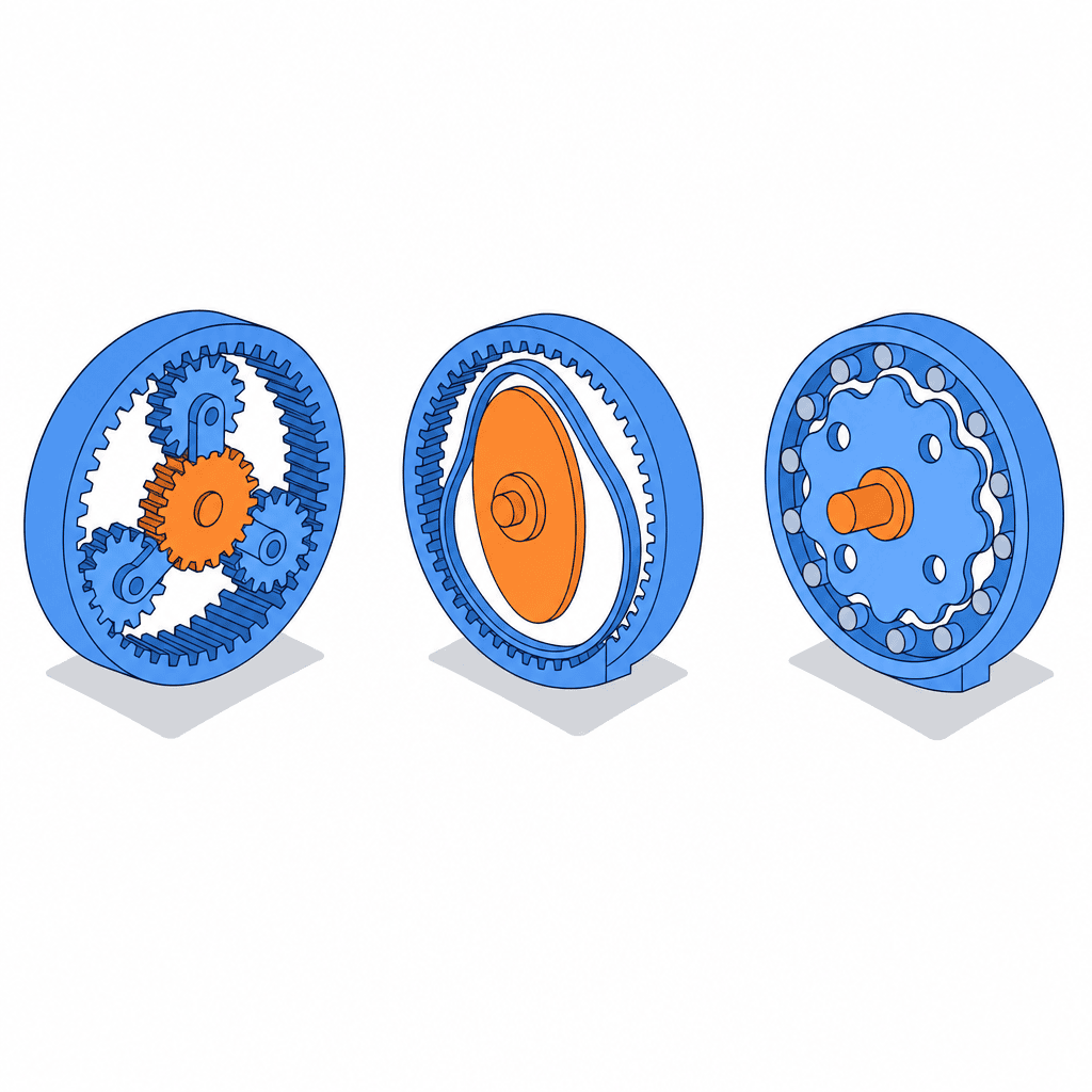
Planetary gearbox
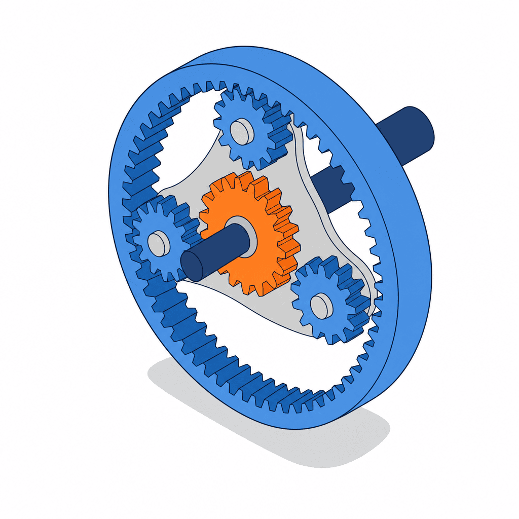
A planetary gearbox is built from three elements — a central sun gear, several planet gears orbiting around it, and an outer ring gear. Because multiple planet gears share the load simultaneously, torque capacity is high relative to the external dimensions, and input and output are coaxial. This is the most widely adopted arrangement for servo motor gearheads, and it is the most affordable of the three types.
Backlash varies enormously with the specification grade. Taking the Sumitomo Heavy Industries IB series of planetary gearboxes for servo motors as an example, the published figures are 15 arc-minutes for the PE type, 3 or 15 arc-minutes for the P1 type, 3 arc-minutes for the P2 type, and 6 or 15 arc-minutes for the PK1 type. In other words, a five-fold spread exists inside what everyone calls simply a planetary reducer. Note that these are the published values for that series, and high-precision grades of 1 arc-minute or less are commercially available from other manufacturers. When comparing planetary gearboxes, you have to read down to the type code, not just the series name.
Wave gear reducer (harmonic drive)
A wave gear reducer consists of three components — a wave generator, a flexspline and a circular spline. According to the explanation published by Harmonic Drive Systems, the circular spline carries two more teeth than the flexspline, and that two-tooth difference is the reduction principle itself. A single stage yields a high reduction ratio in the range of 1/30 to 1/320.
The source of the accuracy is the sheer number of teeth in mesh. The company states that approximately 30 percent of the total tooth count is engaged at any moment, so the load is distributed and the force carried by any individual tooth is very small. This symmetrical, multi-point engagement is described as producing very small backlash together with high positional and rotational accuracy. The type is compact and light, lends itself to a hollow construction, and is the usual choice for robot wrist axes and small indexing axes.
Cycloidal reducer
Sumitomo Heavy Industries has produced this type for many years, using a circular-arc (trochoidal) gear mechanism based on a proprietary curve known as the epitrochoid parallel curve. Rather than the sliding contact of a conventional involute gear, power is transmitted through smooth rolling contact, and the company lists freedom from tooth breakage, excellent shock resistance, high efficiency and long service life as the resulting characteristics. The line-up is extremely broad, covering capacities from 0.1 kW to 132 kW and reduction ratios from 2.5 to 658503.
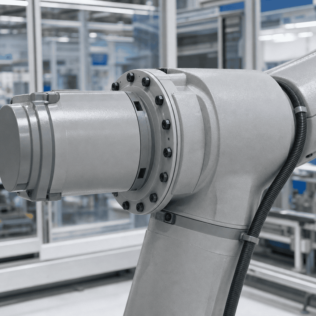
The Nabtesco RV precision reducer also uses trochoidal gearing. Nabtesco explains that supporting the gears on multiple shafts, combined with machining accuracy on the order of one micrometer, delivers high rigidity and low backlash together. Hollow versions that allow wiring and air tubing to pass through the center are also offered, and the type is standard practice for robot swivel axes and large positioners.
Summarized side by side, the character of each type looks like this.
| Item | Planetary | Wave gear | Cycloidal (trochoidal) |
|---|---|---|---|
| Typical reduction ratio (single stage) | Roughly 3 to 10 | 1/30 to 1/320 | 2.5 to 658503 (multi-stage included) |
| Backlash guideline | Mostly 3 to 15 arc-minutes by grade; high-precision units of 1 arc-minute or less exist | Very small | Within 1 arc-minute in precision grades |
| Strong applications | Servo drive axes, travel axes, general-purpose gearheads | Robot wrist axes, small indexing axes, axes needing a hollow center | Robot swivel axes, positioners, conveyors, agitators |
| Shock resistance | Moderate | Moderate (overload damages the flexspline) | High (rolling contact, no tooth breakage) |
| Relative price band | Low | High | Medium to high |
| Representative manufacturers | Sumitomo Heavy Industries, Nissei, various makers | Harmonic Drive Systems | Sumitomo Heavy Industries (Cyclo), Nabtesco (RV precision reducer) |
The table above describes general tendencies by type, and the actual figures shift with series and frame size. The Nabtesco RV-N series, for instance, is published with backlash within 1 arc-minute and lost motion within 1 arc-minute, with rated torque running from 245 N·m for the RV-25N up to 7000 N·m for the RV-700N, and with reduction ratios set as several discrete models per size across the range of 41 to 203.52. These are not continuously selectable values but fixed figures tied to each model code. Once you have narrowed the field to two or three models, always open the specification sheet for that exact size and confirm.
Backlash and lost motion — what accuracy actually means
Backlash is a term used constantly in the field, but the catalog carries a second entry alongside it called lost motion. The two are not the same thing.
Backlash is the angular play that appears when the output shaft is turned gently in the forward and reverse directions. It refers to the clearance between the tooth flanks themselves. Lost motion is a value measured by applying a small torque of a few percent of the rated torque in both directions, and it includes the torsional deflection of the components, so elastic deformation is folded in on top of the clearance. Repeatability of positioning is governed mainly by backlash; the ability to follow a changing load is governed mainly by lost motion and rigidity.
To build a feel for the numbers, convert them into angles. One arc-minute is 60 arc-seconds, and one degree is 3600 arc-seconds. Three arc-minutes is therefore 0.05 degrees, and one arc-minute is about 0.0167 degrees. Seen at the tip of an arm with a 500 millimeter radius, one arc-minute of play corresponds to about 0.15 millimeters of movement and three arc-minutes to about 0.44 millimeters. If the requirement reads “within 0.2 millimeters at the tip”, a 3 arc-minute unit is geometrically impossible. Doing this conversion first makes type selection go remarkably quickly.
Model case — selecting three axes at a Japanese auto parts plant in Chonburi
From here the discussion runs on a concrete example. The setting is an assembly line at a Japanese-owned automotive parts manufacturer located in an industrial estate in Chonburi province, Thailand. The project is not a partial update of an existing line but the construction of a new sub-line in the adjacent floor space, and reducers have to be selected for three drive axes of quite different character.
| Axis | Application | Requirement |
|---|---|---|
| Axis A | Camera positioning stage for visual inspection (rotary indexing) | Index 90 degrees in 0.4 seconds, stopping accuracy within ±0.02 degrees |
| Axis B | Tilting positioner for a welding jig | Reverse through 180 degrees in 1.5 seconds, workpiece and jig totaling 50 kilograms |
| Axis C | Drive axis of a pallet conveyor | Conveyed mass 200 kilograms, speed 20 meters per minute, continuous operation |
For each of the three, the required torque is built up from the components below.
Axis A — accuracy decides the type
Take the load-side moment of inertia as 0.045 kg·m². Indexing 90 degrees in 0.4 seconds with a triangular profile (acceleration and deceleration only) gives an acceleration time of 0.2 seconds over an acceleration arc of 45 degrees, that is 0.7854 radians. Angular acceleration is 0.7854 divided by 0.5 times 0.2 squared, which is 39.3 rad/s². Acceleration torque is 0.045 multiplied by 39.3, giving 1.77 N·m. Allowing 0.3 N·m for friction and applying a safety factor of 1.5, the required output torque is about 3.1 N·m.
What decides the type here is not torque but accuracy. The requirement is ±0.02 degrees, in other words ±72 arc-seconds. A 3 arc-minute planetary unit is 180 arc-seconds, so it drops out of contention at this point. Either a class of 1 arc-minute or less, or a wave gear reducer with its very small backlash, is needed. Torque on Axis A is low and a hollow construction was also required so that the camera wiring could pass through the center, so a wave gear reducer was selected.
The reduction ratio is set at 50. Checking the inertia ratio, 0.045 divided by 50 squared gives 1.8 × 10^-5 kg·m². The rotor inertia of a 100 W class servo motor is broadly in the range of 0.5 × 10^-5 to 0.8 × 10^-5 kg·m², so the inertia ratio comes out at roughly 2 to 3.5, comfortably inside the region where the control loop is stable. Now check the speed side. Average angular velocity is 225 degrees per second, and the peak of a triangular profile is twice that, which is 75 revolutions per minute at the output, or 3750 revolutions per minute at the motor. Maximum speed for a 100 W class servo from the major manufacturers is generally around 6000 revolutions per minute, so the selection holds. Had the ratio been set to 100, the inertia ratio would drop further, but the required motor speed would become 7500 revolutions per minute and exceed that ceiling. This is exactly what it means to say a reduction ratio has both an upper and a lower window.
Axis B — moment load decides the type
Take the combined moment of inertia of workpiece and jig as 2.8 kg·m², with the center of gravity offset 0.12 m from the axis of rotation. Turning 180 degrees in 1.5 seconds with a triangular profile gives an acceleration time of 0.75 seconds over an acceleration arc of 90 degrees, that is 1.5708 radians, so angular acceleration is 5.59 rad/s². Acceleration torque is 2.8 multiplied by 5.59, giving 15.6 N·m.
Because this is a tilt axis, gravity torque acts continuously. Fifty kilograms multiplied by 9.81 and by 0.12 meters gives 58.9 N·m. That figure is the gravity torque about the axis of rotation — in other words, the force the motor has to produce. Combined with the acceleration torque it comes to 74.5 N·m, and applying a safety factor of 1.5 the required rated torque is 112 N·m.
What really governs this axis, however, is moment load. The 58.9 N·m just calculated is driving torque, and it is a different quantity from the tipping moment carried by the bearings. Because the jig overhangs 0.15 meters from the output flange face, the bearings carry a moment load of 50 kilograms multiplied by 9.81 and by 0.15 meters, about 73.6 N·m, continuously and without relief. Note that this is calculated from the overhang and is not the 58.9 N·m figure reused. Standard planetary units frequently fall short on allowable output bearing moment, which forces a design change in which an external cross roller bearing takes the load instead. A precision reducer that supports trochoidal gears on multiple shafts and carries a large-diameter bearing built into the output side, as the Nabtesco RV precision reducer does, removes the need for that separate bearing arrangement. Here a unit equivalent to the RV-25N, rated at 245 N·m, was selected. Against the 112 N·m required rated torque including the safety factor, the margin is 2.2 times. Torque is therefore ample, but the selection should be understood as one driven by rigidity and moment load.
Axis C — cost and shock resistance decide the type
Taking a running resistance coefficient of 0.05, the running resistance force is 200 kilograms multiplied by 9.81 and by 0.05, giving 98.1 N. With a drive sprocket pitch circle diameter of 150 millimeters, the required output torque is 98.1 multiplied by 0.075 meters, which is 7.36 N·m.
Output speed is 20 meters per minute divided by a circumference of 0.471 meters, giving 42.4 revolutions per minute. With the motor at 1500 revolutions per minute the required reduction ratio is 35.4, so the standard ratio of 35 is selected. Running a 0.2 kW gearmotor at a ratio of 35 gives an output shaft torque of 9550 multiplied by 0.2, divided by 42.9, multiplied by an efficiency of 0.9, which is about 40 N·m. Against the bare requirement of 7.36 N·m that is a margin of roughly 5.4 times, ample headroom for an axis running continuously and taking start-stop shock. A right-angle cycloidal gearmotor was selected, the type described as free from tooth breakage.
Building up the price — the reducer itself does not reach 40 percent of the total
Now to cost. What follows is our own estimate on the assumption of procurement in and around Bangkok, Thailand. Actual market prices move with exchange rates, quantities, distributors and delivery terms. Yen-denominated material costs are converted at 1 THB = 4.85 JPY.
For the price band of the reducer itself, the reference point used is a published explanation by Technoreach stating that robot reducers are generally expensive components in the range of JPY 150,000 to 250,000. Converted into baht that is roughly 31,000 to 52,000 THB.
Axis A comes first.
| Item | Quantity | Unit price (THB) | Amount (THB) |
|---|---|---|---|
| Wave gear reducer unit (ratio 50) | 1 | 29,900 | 29,900 |
| Servo motor 100 W plus amplifier | 1 set | 24,000 | 24,000 |
| Coupling and mounting parts | 1 set | 4,800 | 4,800 |
| Machining of stage mounting plate | 1 | 8,500 | 8,500 |
| Customs clearance and inland transport | 1 set | 3,500 | 3,500 |
| Mechanical assembly and alignment | 1.0 man-day | 4,200 | 4,200 |
| Control wiring and origin adjustment | 1.5 man-days | 4,200 | 6,300 |
| Axis A total | 81,200 |
Next comes Axis B, where the moment load is carried by a precision reducer. Not only does the unit price rise, but the machining accuracy demanded of the jig mounting plate on the output side rises with it, so the surrounding costs move in sympathy.
| Item | Quantity | Unit price (THB) | Amount (THB) |
|---|---|---|---|
| Precision reducer (RV type, size 25 equivalent) | 1 | 45,400 | 45,400 |
| Servo motor 750 W plus amplifier | 1 set | 38,000 | 38,000 |
| Motor mounting flange and input pinion | 1 set | 9,700 | 9,700 |
| Machining of jig mounting plate | 1 | 12,000 | 12,000 |
| Customs clearance and inland transport | 1 set | 3,500 | 3,500 |
| Mechanical assembly and alignment | 1.5 man-days | 4,200 | 6,300 |
| Control panel modification, wiring and origin adjustment | 2.0 man-days | 4,200 | 8,400 |
| Initial grease and seals | 1 set | 2,600 | 2,600 |
| Axis B total | 125,900 |
Finally there is Axis C, where a standard gearmotor is sufficient. Because it runs on an inverter, no servo amplifier is needed and the figures drop by an order of magnitude.
| Item | Quantity | Unit price (THB) | Amount (THB) |
|---|---|---|---|
| Right-angle gearmotor 0.2 kW (ratio 35) | 1 | 13,400 | 13,400 |
| Base, sprockets and chain | 1 set | 7,200 | 7,200 |
| Inverter 0.4 kW | 1 | 6,800 | 6,800 |
| Customs clearance and inland transport | 1 set | 2,000 | 2,000 |
| Installation and tension adjustment | 1.0 man-day | 4,200 | 4,200 |
| Electrical wiring | 1.0 man-day | 4,200 | 4,200 |
| Axis C total | 37,800 |
The three axes come to 244,900 THB in total. Of that, the reducers themselves account for 29,900 plus 45,400 plus 13,400, which is 88,700 THB, or 36.2 percent. The remaining 64 percent or so is motors and amplifiers, coupling parts, machining, transport, and the labor of installation and commissioning. Negotiating a 10 percent discount on the reducers moves the total by only 3.6 percent, and holding that structure in mind changes how much time is worth spending on price negotiation.
What happens if you drop to a cheaper type
So how much would actually be saved by replacing Axis A and Axis B with inexpensive planetary units?
Substituting a precision planetary 3 arc-minute unit on Axis A (assumed at 12,400 THB) frees up 17,500 THB. But 3 arc-minutes of backlash is 180 arc-seconds, which does not meet the ±72 arc-second requirement. If the stop position scatters, the workpiece moves within the camera field of view and misjudgments in inspection increase. This is not a cost question but a failure to meet specification.
Substituting a 6 arc-minute planetary unit on Axis B (assumed at 22,000 THB) frees up 23,400 THB. However, allowable moment load is then insufficient, so an external cross roller bearing (assumed at 14,500 THB) and machining of the flange that holds it (assumed at 9,800 THB) become necessary. That is 24,300 THB of additional cost, leaving a net 900 THB out of pocket. The higher part count also raises assembly hours and makes alignment more difficult, so in practical terms it is clearly the more expensive route.
What these two examples show is that comparing reducer prices on the unit cost alone leads to the wrong decision. The correct comparison is between complete configurations that each satisfy the requirement specification. The same logic applies to other drive elements, and the article on air cylinder selection criteria sets out the same way of thinking, comparing totals that include valves, sensors and piping rather than the cylinder in isolation.
Maintenance — grease replacement, abnormal noise and growing backlash
Installation is not the end of the story. Wear advances reliably from the high-speed input side, and the lubricant degrades through oxidation and the ingress of iron particles.
Setting a grease replacement interval
For general-purpose small geared motors, the Nissei FAQ states that grease replacement is unnecessary in most cases, while also advising that changing it at a guideline of 10,000 hours will make the unit last considerably longer. At the same time it makes clear that customers cannot change the grease themselves and that the work has to be carried out as a repair request to the manufacturer. Since disassembly is involved, opening the unit on site risks falling outside the warranty.
For reducers built into robots, the Technoreach explanation treats reducer grease replacement as something generally performed once every three to four years, citing the J1, J2 and J3 axes as examples. Grease degrades through oxidation and through contamination by iron particles generated as the gears wear.
These two guidelines do not contradict each other. Converted into annual actual operating hours they overlap. Two shifts, eight hours a day, 22 days a month, twelve months a year gives 4,224 hours per year, and multiplying by an actual utilization rate of 60 percent gives about 2,534 hours a year. Dividing 10,000 hours by that figure yields 3.9 years, which lines up almost exactly with the three-to-four-year cycle. Running the same calculation for your own operating pattern lets you back a calendar-based maintenance plan with real numbers.
Do use the specified lubricant. Nabtesco supplies RVGREASE LB00 and RVOIL SB150 for the RV precision reducer series, and explains that using the optimal lubricant is key to suppressing wear and extending service life. Substituting a general-purpose grease brings a different viscosity and additive design, which can raise input torque and cause premature wear.
Judging grease degradation by measurement
Managing the replacement interval by elapsed years alone will miss the heavily loaded axes. The iron particle concentration criteria published by Technoreach give thresholds that can be used directly on site.
| Assessment | Iron particle concentration | Recommended response |
|---|---|---|
| Normal | 0.050 percent or below | Continue on the normal interval |
| Caution | 0.051 to 0.099 percent | Increase monitoring, plan replacement at the next shutdown |
| Abnormal | 0.100 percent or above | Replace early, consider internal inspection |
Sending a sampled grease specimen out for analysis is worth the effort because recovery costs escalate sharply once a failure has occurred. The same source notes that when a reducer fails, the high repair cost is compounded by a line recovery period that can exceed one month, with delivery lead times of one to two months given as the reason. In a plant in Thailand, shipping time from Japan is added on top of that, so the effective downtime risk is larger still. For axes that are critical to production, the decision on whether to hold a spare reducer should be made by setting the loss per day of stoppage alongside the unit price.
Separating abnormal noise from growing backlash
Abnormal noise can be narrowed down to some extent by how it sounds. Industry guidance sets out the following correspondence.
| Character of the noise | Likely cause |
|---|---|
| Rumbling | Possible bearing damage |
| Groaning or humming | Poor tooth flank contact or gear accuracy |
| Rattling | Excessive backlash or loose mounting |
| Periodic knocking | Possible chipped tooth or localized damage |
When the noise first appears is an equally important clue. The same guidance separates noise arising immediately after installation, which points to assembly error, misalignment or an initial defect, from noise appearing after a long period of use, which points to wear, bearing degradation or poor lubrication. The items listed for checking on site are lubricant quantity and condition, looseness of the mounting bolts, how the noise changes when the load varies, and bearing and housing temperature, with the observation that diagnostic accuracy improves when temperature, vibration and leakage are examined together with sound rather than sound alone.
Growth in backlash is a form of degradation that is hard to notice because it advances slowly. On a positioning device it shows up as a gradually widening scatter of stop positions for the same command, or as noise that appears only during reversing motion. Recording servo following error and torque waveforms periodically lets you catch it as a trend. On equipment where multiple axes work together, as with robots, the differences in load distribution between axes discussed in industrial robot introduction 2026 show up as differences in wear rate, so the practical approach is to inspect the heavily loaded axes first rather than putting every axis on the same interval.
Causes of grease leakage
Almost all leakage originates at the oil seals and the mating faces. The typical routes are hardening and cracking of the seal material through high ambient temperature and age, internal pressure rising and pushing the seal lip open, and scoring of the shaft so that the sealing face can no longer be maintained. Left alone, the resulting lack of lubrication accelerates wear in the gears and bearings, so rather than wiping the leak away and watching what happens, record the quantity and the location and eliminate the cause.
In plants in Thailand, two conditions push seal degradation and lubricant emulsification along faster — many processes run at ambient temperatures higher than those in a Japanese plant, and the high humidity of the rainy season makes moisture ingress through the breather more likely. For locations with harsh conditions, such as conveying equipment close to outdoor areas or the surroundings of pre-treatment before painting, it is safer to set a shorter replacement interval from the start.
Common selection mistakes and how to avoid them
To close, here are the failures that recur across real projects.
First, selecting on torque alone and never looking at moment load. The catalog rated torque is satisfied, yet the output shaft deflects and positioning will not settle. Always calculate the tipping moment from the mass of the jig and its overhang from the output flange face.
Second, confusing acceleration torque with static load torque. On an indexing axis the acceleration torque dominates, and choosing on standstill torque alone can leave the unit short of capacity by a factor of two or more.
Third, treating a larger reduction ratio as inherently safer. The inertia ratio falls, but the selection collapses once the motor speed exceeds its ceiling. Draw the upper and lower window first.
Fourth, ordering by series name without confirming the backlash grade. Because 3 arc-minute and 15 arc-minute versions coexist within one series, quotation requests must specify the full model code.
Fifth, comparing prices on the unit alone. In the estimate in this article the reducers themselves came to about 36 percent of the total. Compare complete configurations that include coupling parts, machining and installation labor.
Frequently asked questions
What is a reducer
It is a device that lowers the rotational speed of a motor through gearing in order to obtain a larger torque. The principle is the same as selecting a lighter gear on a bicycle, where cadence rises but the pedal force required falls, converting speed of rotation into force. In an industrial robot, the presence of a reducer is what allows even a compact motor to deliver a large force.
What should be decided first when choosing a reducer
Three things — the required output torque, the required output speed, and the positioning accuracy demanded of the machine. Torque is built up from acceleration torque, gravity torque and friction torque, then multiplied by a safety factor. Positioning accuracy is converted into an angle and checked against the backlash specification. Only once all of that has been quantified do you begin narrowing down type and size.
Is a reducer always necessary in a servo motor drive
No. If the load torque is small, the inertia ratio is sufficiently low and the required speed falls inside the motor rated range, direct coupling works. The two reasons for adding a reducer are torque amplification and reducing load inertia by the square of the ratio to stabilize the control loop. If the symptom is slow settling caused by an excessive inertia ratio, adding a reducer is an effective option.
How much does a reducer cost
It varies greatly with type and size. For reference, published guidance describes robot reducers as expensive components generally in the range of JPY 150,000 to 250,000, which converts to roughly 31,000 to 52,000 THB. General-purpose small-capacity gearmotors sit an order of magnitude below that. In the Thai plant model case in this article, however, the reducers themselves came to about 36 percent of the total equipment cost, with the balance in coupling parts, machining and installation and commissioning labor. Build your budget on the total, not the unit price.
What is the guideline for reducer replacement timing
It depends heavily on the application, but two published guidelines exist for lubricant replacement. For general-purpose small geared motors, replacement is described as unnecessary in most cases, with 10,000 hours given as a guideline, and the work must be carried out as a repair request to the manufacturer. For reducers built into robots, grease replacement once every three to four years is generally recommended. Converted into annual actual operating hours the two roughly coincide. A more reliable method is to measure the iron particle concentration of a sampled grease specimen and judge on the basis that 0.050 percent or below is normal, 0.051 to 0.099 percent calls for caution, and 0.100 percent or above is abnormal.
What is the difference between a cycloidal reducer and a harmonic drive
They differ in both principle and strong territory. A cycloidal reducer uses circular-arc gearing based on the epitrochoid parallel curve and transmits power through smooth rolling contact, so there is no tooth breakage, shock resistance is excellent, and the range covers capacities from 0.1 kW to 132 kW and ratios from 2.5 to 658503. It suits continuous duty with shock loading, such as conveyors and agitators. A harmonic drive is a wave gear reducer, achieving a single-stage ratio of 1/30 to 1/320 through the combination of components differing by two teeth, and because approximately 30 percent of the total tooth count is engaged simultaneously, backlash is very small and positional accuracy is high. It is compact and light, easily made hollow, and suits robot wrist axes and precise indexing axes.
Can reducer backlash be adjusted afterwards
Precision reducers are generally not built to allow the user to adjust backlash. Some arrangements such as certain worm gear designs do have an adjustment mechanism, but planetary, wave gear and trochoidal precision reducers have their accuracy built in during factory assembly. The required accuracy therefore has to be satisfied at the selection stage. If backlash grows after the equipment enters service, treat it as a signal that wear is progressing and move on to checking the lubricant condition and considering replacement.
Summary
Gearbox reducer selection is the work of filling in six criteria as numbers derived from the requirement specification — reduction ratio, allowable torque, backlash, allowable load, service life and price. Types fall into three broad families, planetary, wave gear and cycloidal, and the shortlist forms naturally once you know which factor dominates. Where accuracy dominates, choose a low-backlash type. Where moment load dominates, choose a rigid precision reducer. Where continuous duty and shock dominate, choose the rolling-contact type. In the Thai plant model case in this article, the reducers themselves came to about 36 percent of the 244,900 THB total across three axes, and the estimate for dropping to cheaper types showed the saving all but wiped out by additional peripheral parts. After installation, building a lubricant replacement interval calculated backward from annual actual operating hours, condition monitoring by iron particle concentration, and a routine for diagnosing abnormal noise into daily operation is what keeps a long-lead-time component from stopping the line without warning.
TOMAS TECH supports Japanese-owned plants across Thailand end to end, from equipment design through installation to maintenance after commissioning. We are happy to be consulted at the stage where the reducer model has not yet been decided, or where the question is simply which type suits a given motion, and we can start alongside you from organizing the requirement specification and calculating the required torque. If you have a project under consideration, please get in touch through our contact page.
References
- What Is a Reduction Gear (Nabtesco definition of a reducer, its role in industrial robots, and the development background of the RV precision reducer)
- Three Features of the RV Precision Reducer (adoption of trochoidal gearing, machining technology on the order of one micrometer, and the hollow type construction)
- RV-N Series Precision Reducer Product Specifications (backlash within 1 arc-minute, lost motion within 1 arc-minute, ratios from 41 to 203.52, rated torque from 245 to 7000 N·m)
- Cyclo Reducer (Sumitomo Heavy Industries on the epitrochoid parallel curve principle, rolling contact, capacities from 0.1 to 132 kW, ratios from 2.5 to 658503)
- IB Series Planetary Gearboxes for Servo Motors (backlash specifications by type, PE 15 arc-minutes, P1 3 or 15 arc-minutes, P2 3 arc-minutes, PK1 6 or 15 arc-minutes)
- Principle of the Harmonic Drive (three-component construction, two-tooth difference, ratios from 1/30 to 1/320, approximately 30 percent of total teeth engaged simultaneously)
- Lubricants (Nabtesco genuine RVGREASE LB00 and RVOIL SB150, and the effect of dedicated lubricants on service life)
- FAQ on Grease Replacement (Nissei guideline of 10,000 hours, and the operational constraint that customers cannot perform the replacement themselves)
- Grease Replacement on FANUC Robots (replacement cycle of three to four years, reducer price band and delivery lead time of one to two months, iron particle concentration criteria for normal, caution and abnormal)
- Causes of Abnormal Noise in Reduction Gears (correspondence between noise types and likely causes, separating initial defects from age-related degradation, and on-site check items)


