


A quotation for a Thailand factory machine may say, “Use a dual-contact emergency-stop button and one safety relay.” That is a component list, not proof that hazardous motion will stop. A safety relay evaluates inputs and controls safety outputs. The complete safety function also includes the sensor, wiring, contactor or safety drive input, physical stopping behavior and conditions for restart. This guide helps machine owners and purchasing teams compare relay architectures, reset and external device monitoring (EDM), outputs, required PL or SIL, and FAT/SAT evidence. Confirm exact terminals, configurations and certification conditions against the current manual for the selected model.
1. Write the safety function before choosing a part number
ISO 12100:2010 provides principles for machinery risk assessment and risk reduction. ISO 13849-1:2023 provides a method for designing and integrating safety-related parts of control systems; it does not prescribe the safety function or required performance level (PLr) for every machine. Identify the hazard, task, access path, stopping time and foreseeable misuse for the actual equipment. Define each needed function and its required performance. An IEC 62061 SIL approach may also be used where applicable. In either method, a product’s advertised maximum capability does not determine the achieved performance of the complete function.
Write each function as an end-to-end statement: which input detects the condition, which hazardous motion stops, what constitutes the safe state, by when it must be reached and what prevents unexpected restart. For example: “When E-stop E1 is actuated, stop the hazardous conveyor axis and inhibit restart until the cause is removed and a deliberate manual reset is completed.” Write separate rows for a guard door, optoelectronic protective device and maintenance mode, even if they share a final output.
| Item | Procurement input | Evidence |
|---|---|---|
| Hazard and task | Motion, approach and intervention point | Risk assessment, layout |
| Input | E-stop, guard and sensor channels | Part numbers, wiring diagram |
| Logic | Reset, fault retention, cross-short detection | Settings, logic diagram |
| Output | Contactor or drive safety input | Power circuit, safety manual |
| Performance | PLr or SIL requirement, stopping time | Calculation, measurement plan |
| Validation | Normal, fault, power-return and restart tests | FAT/SAT record |
An E-stop is not a substitute for a guard or other risk reduction. It assumes someone can notice a hazard and act, which may be too late. Evaluate inertia, residual pneumatic pressure, gravity and access before buying a relay. If the required function is defined after procurement, the relay, sensors and contactors may all need redesign.
2. Draw the complete path from detection to safe state
Pilz describes safety relays for E-stop, guard and light-curtain functions, including internally monitored and redundant arrangements. It also describes a feedback loop for monitoring external contactors. Exact input count, cross-fault detection, output technology and starting behavior vary by model. A “maximum PL e” statement is device data under defined conditions, not proof of the machine’s function.
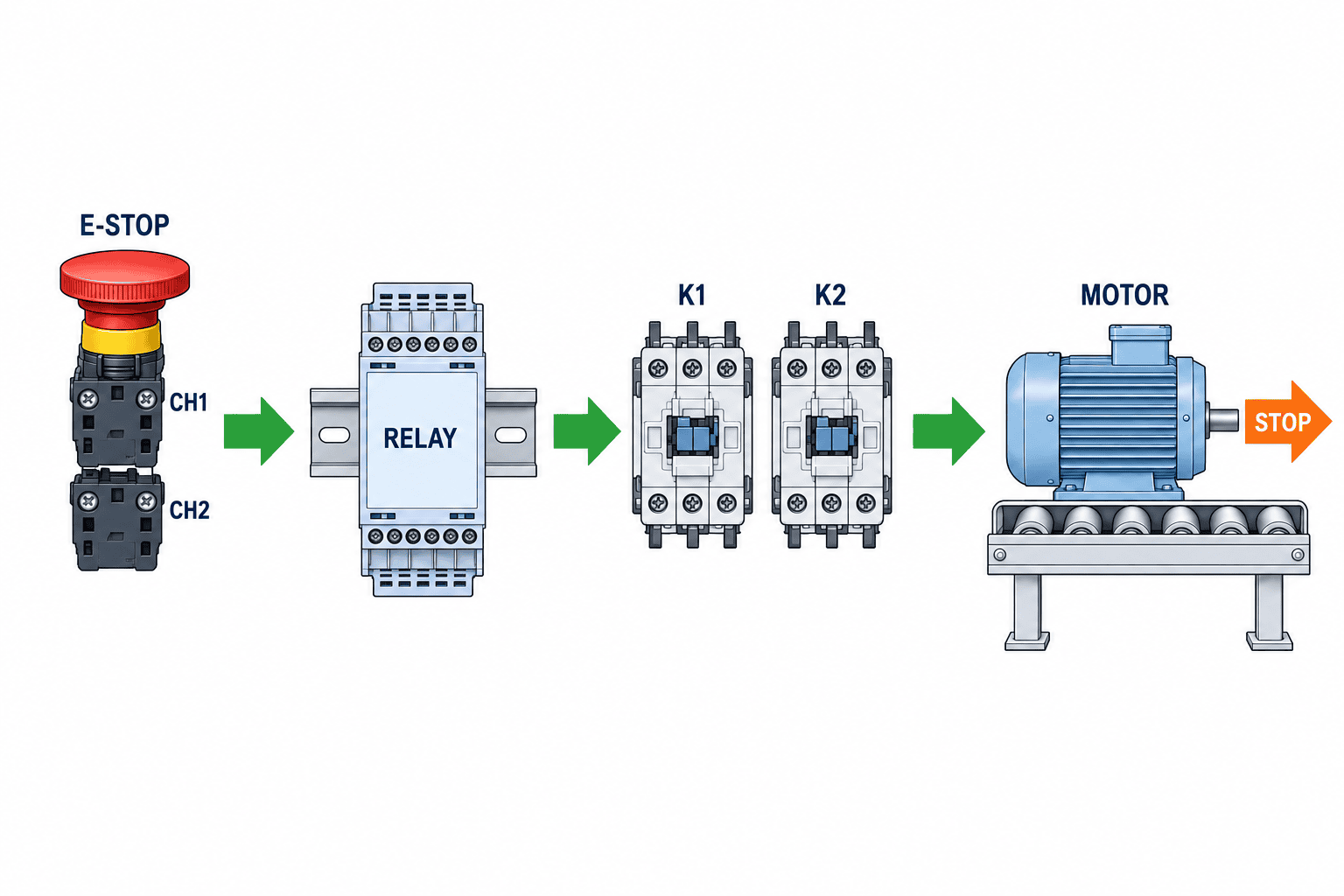
Assess five boundaries: the input device, the input wiring, the relay evaluation and safety output, the final switching device, and the physical machine response. Figure 1 shows only the conceptual sequence: E-stop input modules, safety relay decision, K1/K2 final switching, and stopped motor. It is not a wiring diagram and does not show EDM return connections. If a normal PLC bypasses part of the stop path, or a welded contactor is left undetected where diagnostics are required, the relay label cannot be transferred to the system. Actual channel count and circuit design must follow the selected device manuals and whole-function validation.
If one relay handles an E-stop and a guard, define which axes each input stops, whether their reset rules differ and whether maintenance needs separate fault identification. Do not combine unrelated functions merely because a module has spare inputs. For guard doors, decide whether the door must remain locked until motion stops and who authorizes restart. Our guide to selecting safety door switches covers mounting, displacement and bypass concerns. If the switch supplies OSSD signals, verify that the chosen relay input accepts the sensor and its test pulses. For a scanner, detection field and stopping distance must be designed first; see the safety laser scanner selection guide.
3. Two input channels must provide useful diagnostics
Connecting two NC E-stop contacts to independent relay channels is common, but two wires alone do not establish diagnostic coverage. Check how the selected product and wiring detect one broken channel, a stuck contact, a cross-short between channels or a short to supply. Some models use test outputs; OSSD sensors may have model-specific compatibility conditions. Splitting one signal into two input terminals does not create independent channels.
The Siemens 3SK1 manual documents sensor channels, test outputs, start-button wiring and feedback circuits. The 3SK2 manual describes ways to integrate output expansions and downstream contactor feedback into its logic. These are product-specific examples, not universal terminal conventions. A quotation that names only a “3SK family” does not settle the part number, terminal layout or settings. Record sensor model, cable length and route, electrical output type, startup state and fault state together.
When several doors are wired in series, assess whether one fault may be masked by operation of another door and whether maintenance can identify the door that stopped the machine. Include diagnostics and repair instructions in delivery. A circuit that is difficult to diagnose invites temporary jumpers, which can defeat the protection.
4. Reset is a separate decision from starting the machine
Automatic re-enabling of safety outputs after a sensor becomes healthy and a deliberate manual reset have different consequences if somebody can remain inside a hazardous area. Place a reset control where the operator can verify the area is clear. A reset should not itself issue the machine’s normal run command. Test door closure, E-stop release, restored communications and power return separately.
For monitored manual reset, verify which pushbutton edge is evaluated, whether a held button can enable the outputs and whether an old start signal remains after a fault clears. Section 8.9.2.4 (page 212) of the Siemens 3SK1 manual describes a feedback fault condition in which a start signal detected during the fault may cause startup when the fault clears, as well as a connection method that changes this behavior. Thus the setting name alone does not prove all restart paths are closed. Include held-button, power-return, EDM-fault-clear and upstream-PLC-start-signal cases in FAT.
A large machine with blind spots may require area subdivision or further protection against a person remaining inside. These are layout and work-practice decisions, not relay configuration values. Confirm visibility and actual access routes during SAT.
5. Use EDM to monitor the final switching elements
External Device Monitoring uses feedback contacts to check devices downstream of the safety relay, often contactors. Pilz explains the feedback loop and Omron’s SR1 information describes an NC EDM loop and available reset modes. Do not generalize EDM as immediate detection of every welded contact during operation: detection timing and response depend on device, circuit and configuration.
A typical design evaluates mechanically linked NC auxiliary contacts of contactors before allowing another start. Verify the relationship between auxiliary and main contacts, suitable contactor data, wiring and treatment of short circuits. Sending a normal PLC “running” bit back as feedback does not directly demonstrate that the final contactor opened. Document the response to an auxiliary contact stuck closed as well as a contactor that fails to release.
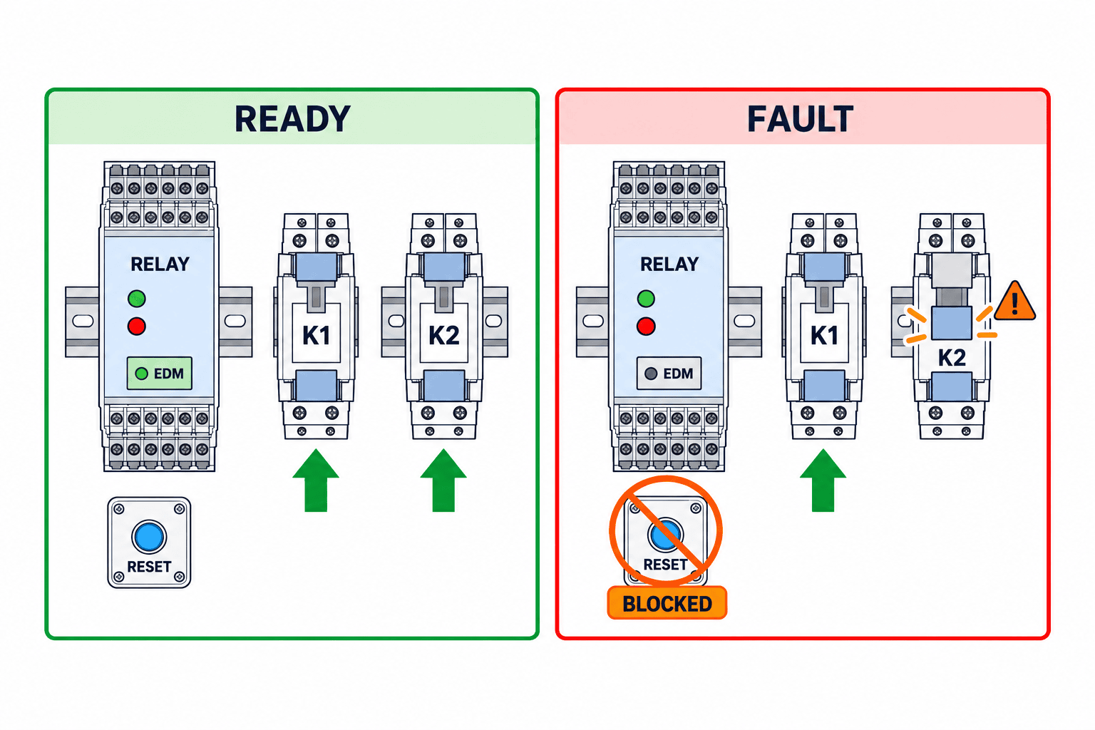
Figure 2 illustrates a conceptual EDM state check of K1 and K2 before restart; it is not a wiring guide. Some relays combine EDM and start on an input. A jumper installed simply to make the machine run changes the function. The actual circuit and schematic must follow the selected device manuals and whole-function validation. In a controlled FAT setup, simulate one contactor failing to return, an open EDM wire and an EDM circuit open on power return. The test fixture must avoid energizing hazardous power merely to create a fault.
6. Compare outputs by the stopping path and load
Safety relays offer relay contacts, semiconductor outputs, delayed outputs and expansion modules in different combinations. Distinguish safety outputs from signaling outputs. Specify whether outputs switch contactor coils or connect to drive STO inputs. A comparison table should show number and type of safety outputs, permitted load, supply, coil inrush and hold current, surge suppression, semiconductor leakage, response time and fault behavior. “Three outputs” is not sufficient if one is only for indication.
For contactor coils, confirm switching duty and electrical life. For STO, follow the drive’s safety manual for two-channel wiring, pulse compatibility, residual energy and coasting time. STO generally prevents torque generation; it does not mean every load instantly stops. Vertical axes and inertial conveyors may need brakes or mechanical retention. A standard control relay substituted into the safety path needs a justified architecture, diagnostics and fault assessment.
Choose the required stop behavior before the cheapest relay. Immediate removal of power may cause a carried load to fall; a controlled deceleration followed by power removal may be appropriate. Then test the chain of deceleration request, actual speed, brake and final isolation. A delay setting by itself does not prove the machine reached its safe state. Assess loss of electrical supply as a separate case.
7. Compare a safety relay and a safety PLC against identical functions
A relay arrangement is a candidate when there are few functions, simple input-output relationships and maintenance staff can diagnose from a schematic and device indication. A safety PLC becomes a candidate when zones, modes, dependencies, diagnostics and changes grow. Neither architecture is inherently sufficient. Assess required PLr/SIL, wiring and diagnostic architecture, common-cause measures, software control and testability for every function.
| Criterion | Relay proposal | Safety PLC proposal |
|---|---|---|
| Expansion | Additional modules and wiring | I/O capacity and logic changes |
| Diagnostics | LED and auxiliary signal detail | Screen, log and time reference |
| Maintenance | Schematic and spare restoration | Backup, license, edit access |
| Change control | Retest after wiring changes | Impact testing after software changes |
| Handover | Terminal, setting and measurement record | Logic version, checksum and I/O record |
A safety PLC does not automatically repair an incorrectly wired guard, welded contactor or insufficient stopping distance. A relay circuit can be analyzed and validated if its function and faults are clear. Issue the same functional specification and acceptance tests to both bidders. Compare engineering, installation, verification and lifecycle support, not just module count.
8. Validate achieved PL/SIL with system evidence
ISO 13849-1:2023 addresses design and integration. ISO 13849-2:2012 covers validation by analysis and testing of specified functions, category and achieved PL. IEC 62061:2021 addresses the design, integration and validation of machinery safety-related control systems. Identify the applicable edition, customer requirements and machine-specific standards in the contract. This guide cannot make a compliance determination for a particular machine.
For an ISO 13849-1 assessment, retain the PLr, architecture category, MTTFd data, diagnostic coverage (DC), common-cause measures and any justified fault exclusions. Draw one block diagram from sensor through logic to final actuator. Copying a relay’s maximum PL e claim into a calculation misses contactor B10d and switching count, wiring faults and unmonitored portions. Distinguish what a physical test demonstrates from what analysis demonstrates.
Validate each function separately. Test E-stop location and stopping behavior; guard opening and prevention of restart; scanner protection fields at relevant speeds; and mode selection during maintenance. A shared relay does not remove the need for individual evidence. After a retrofit, compare every assumption in the previous validation to the new sensors, contactors and settings.
9. Specify the RFP for a Thailand factory
A foreign brand name alone says little about whether a Thailand plant can maintain the equipment. Supply the equipment number, safety-function table, hazardous-area layout, stopping-time requirement, exact input devices, contactors or drives, power, panel conditions, humidity, dust and cable lengths. State contract standards and editions, site electrical rules, documentation languages, local service and spare-parts expectations. Replace generic “certified” claims with evidence for the exact model and application.
Ask every bidder to return the complete model, hardware and setting version, safe and diagnostic I/O, reset method, EDM circuit, stopping path, setup tool, spares, manual and data needed for PL/SIL calculation. Separate risk-assessment update, circuit design, panel build, FAT, site SAT, stopping-time measurement, training and final drawings in the scope. A cheap relay quote may omit contactors or validation work.
“Equivalent to existing unit” also requires definition. Matching voltage, size and contact count does not guarantee identical monitored-start, EDM, test pulse or fault-clear behavior. Supply measured existing wiring, setting photographs, fault history and stopping-time results. Compare old and new function tables, distinguish mechanical interchangeability from functional equivalence and define retests before approval.
10. FAT: test prohibited behavior under faults
Start FAT by comparing drawings with the assembled machine. Match part numbers, settings, terminals, wire numbers, main and auxiliary contactor contacts, and E-stop and door actuation points. Then operate each input normally. Record that hazardous motion stops, does not restart unexpectedly and requires the specified reset. A lamp going off is insufficient if the final switching device and machine were not observed.
Use an approved safe fault-injection method. Simulate an open input channel, a stuck contact, a cross-short where the design claims detection, an open EDM circuit, a contactor failing to return and a held reset button. If a fault is not detected, compare the result with the documented fault assessment and alternative diagnostic measures. Do not energize hazardous power just to run the test.
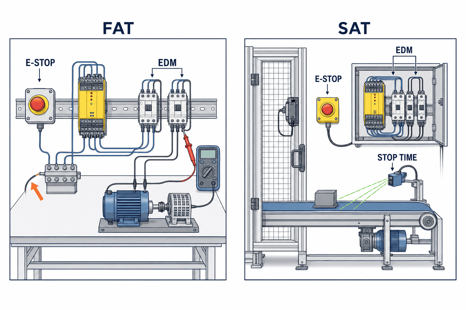
Each FAT record should include test ID, function, drawing and settings revision, input state, action, expected result, measured result, tester and correction. If stopping time is measured in FAT, record speed, load and brake condition. A pre-shipment panel test cannot prove guard geometry or interaction with neighboring machinery after installation.
11. SAT: check site load, access and power restoration
Run SAT on the real supply and at production speeds with relevant minimum and maximum workpieces, pneumatic state, brake state, connected conveyors and installed guards. Record where and under what load stopping time was measured; compare it with the limit set by risk assessment. Open a guard and verify that closing it alone cannot restart the machine. Verify visibility from the reset point and whether a person may remain inside. Test every E-stop location.
Power-return tests should verify both the state while supply is lost and lack of unexpected hazardous motion when supply returns. Test contactor diagnostic recovery, door closure, E-stop release and PLC communication recovery as distinct cases. Check whether a higher-level automatic start request remains pending. The relay may work exactly as specified while another part of the line still creates a hazard.
Hand over final schematics, settings backup, model and serial records, PL/SIL assessment, FAT/SAT results, stopping times, diagnostics and change procedure. Define spare storage, post-replacement tests and local training. For multilingual teams, align the names used on the panel, HMI, drawings and maintenance instructions.
12. Maintain the safety function through modifications
Repeatedly pressing reset until a fault briefly disappears is not a completed repair. For input mismatch, inspect switches, cables, connectors and E-stop contacts. For EDM mismatch, inspect main and auxiliary contactor contacts, feedback wiring and surge measures. Retain the fault history, machine mode, terminal states and replaced part numbers. Replacing the relay without diagnosing the external cause can hide a recurring failure.
If the identical model is unavailable, compare monitored start, EDM timing, test pulses, output loads, default settings, response time and certification rather than only input and output counts. A contactor or drive replacement, guard relocation and control-software change can affect the safety function. Record before-and-after schematics and set the scope of revalidation by the affected functions and fault paths.
13. Stopping time is more than relay response time
A catalogue relay response time cannot alone set guard location or protective-device distance. Put sensor detection, relay output drop, contactor or drive reaction, and physical machine deceleration on the same timeline. Include approach path and worst relevant operating load. A contactor opening is not the moment of safety if a workpiece continues moving under inertia.
State the measurement start and end events: door movement, sensor output change, relay output change and axis reaching the defined safe state are different. Specify instrument resolution, measuring point, speed, workpiece and brake condition. Address repeatability and how a conservative result enters the design. Set triggers for remeasurement after speed changes, load changes or brake wear. If a person can reach the hazard before motion ends, review guard position, access, speed, shielding or braking. The applicable distance calculation standard depends on the machine and protective device; this article provides no universal distance or time.
14. Design diagnostics and recovery for the shop floor
Frequent unexplained trips can encourage repeated resets or bypasses. During selection, verify whether staff can distinguish channel mismatch, open EDM, supply fault and unsatisfied start condition. If indication relies on an LED pattern, put its meaning in the panel documentation. A diagnostic signal sent to the standard PLC or HMI is for display and logging; it must not be confused with a safety output.
Write a recovery method that says who verifies the safe state, when energy is isolated, how inputs and contactors are tested, and what post-repair checks are needed. For a contactor replacement, check contact rating, auxiliary contact construction, linkage and installation, not coil voltage alone. Use consistent terminology across Japanese, Thai and English documents. Match terminal identifiers, drawing references, HMI messages and maintenance steps. Safe troubleshooting depends as much on records and spare-part control as on the relay’s indicator.
15. Avoid misleading low component quotes
A relay-only offer, a safety-PLC offer and an offer with expansion modules cannot be compared by hardware count. Give all suppliers the same safety-function list, input and final switching devices, stopping-time target, and FAT/SAT scope. Require a diagram for each function and explicit exclusions: who supplies contactors, validates existing drive STO, adjusts guards and trains operators?
Compare parts, panel changes, wiring, commissioning, software settings, validation and training in initial cost. For operation, compare spares, tools, configuration access, local support and retest after replacement. A panel or supply upgrade may be needed. Do not invent market prices or lead times from general product literature; request project-specific quotations. Include editable drawings, PDF copies, BOM, settings backup, assessment and test results in deliverables. Define whether the supplier is responsible only to panel terminals or through the machine reaching a safe state.
16. Questions to ask before purchase
At design review, point on the drawing to each hazardous movement, the condition that counts as stopped, and every approach path. Ask which safety function covers each E-stop, guard and sensor; which zone a single fault stops; and whether recovery in one zone can move another axis. If these are unclear, revise requirements before comparing part numbers.
At circuit review, ask how a short between channels is detected, where each safety output reaches a final switching element, how EDM verifies opening, and whether an old start signal survives power or fault recovery. Match the exact manual page for the proposed model to its diagram and settings. At acceptance review, ask how faults will be injected safely, whether stopping time is measured at real load, how FAT and SAT differ, and who holds the final settings backup.
Keep the original risk assessment, function table and stopping-time results after commissioning. A later guard relocation, faster conveyor or heavier workpiece may invalidate an earlier assumption even when the relay part number is unchanged. Record the reason for each change, affected terminals, settings, functions, retest result and approver. This history lets the next maintenance team understand why a particular reset and EDM design was selected.
Conclusion
Select a safety relay by defining the hazard and safety function; drawing the input, logic, final switching and physical stop path; specifying reset and EDM behavior under faults; assessing achieved PL/SIL; and validating stop and restart prevention in FAT and SAT. Compare part numbers inside that framework. For a Thailand factory, issue the same function table and acceptance tests to bidders and include local service in the comparison.
If you are defining E-stop, guard and contactor scope or planning a retrofit, contact TOMAS TECH. We can help clarify the design, procurement and acceptance questions while the requirements are still being formed.
Frequently asked questions
Can two ordinary relays replace a safety relay?
Two devices alone do not establish coverage for welded contacts, wiring faults, common causes, diagnostics or restart prevention. Assess the complete function and its architecture. Pilz describes welded contacts as a typical hazard for ordinary electromechanical relays.
Does a PL e capable relay make the machine PL e?
No. The product claim is conditional device data. Assess input, wiring, logic, final elements and diagnostics together, and derive the PLr for the actual machine from risk assessment.
Does EDM detect every welded contactor immediately?
No universal timing can be assumed. A common design prevents the next start when feedback does not confirm opening. Confirm the exact monitoring behavior in the selected manual and simulate the fault in FAT.
Does manual reset guarantee no start after power returns?
A setting name is not enough. Test a held button, power return, clearing of an EDM error and pending PLC start requests. Separate reset from the normal run command.
Relay or safety PLC?
Compare function and zone count, change frequency, diagnostics, maintenance resources, required performance and verification effort. Both options need the same functional evidence.
Is SAT necessary after a successful FAT?
Installation changes load, guard position, supply, stopping time and operator access. Specify which tests must be repeated under site conditions.


