


Selecting a safety door switch is more than matching a part number to a gate. Does opening the gate initiate a stop early enough? Must the gate remain locked until hazardous motion has ceased? Can a person enter and be trapped inside the enclosure? What happens after a broken wire, power failure or switch fault? A Thai factory ordering or modifying machinery should specify these questions before requesting a quotation. This guide covers interlock switches, guard locking, trapped keys where appropriate, safety circuits, procurement and FAT/SAT.
First separate gate monitoring from guard locking
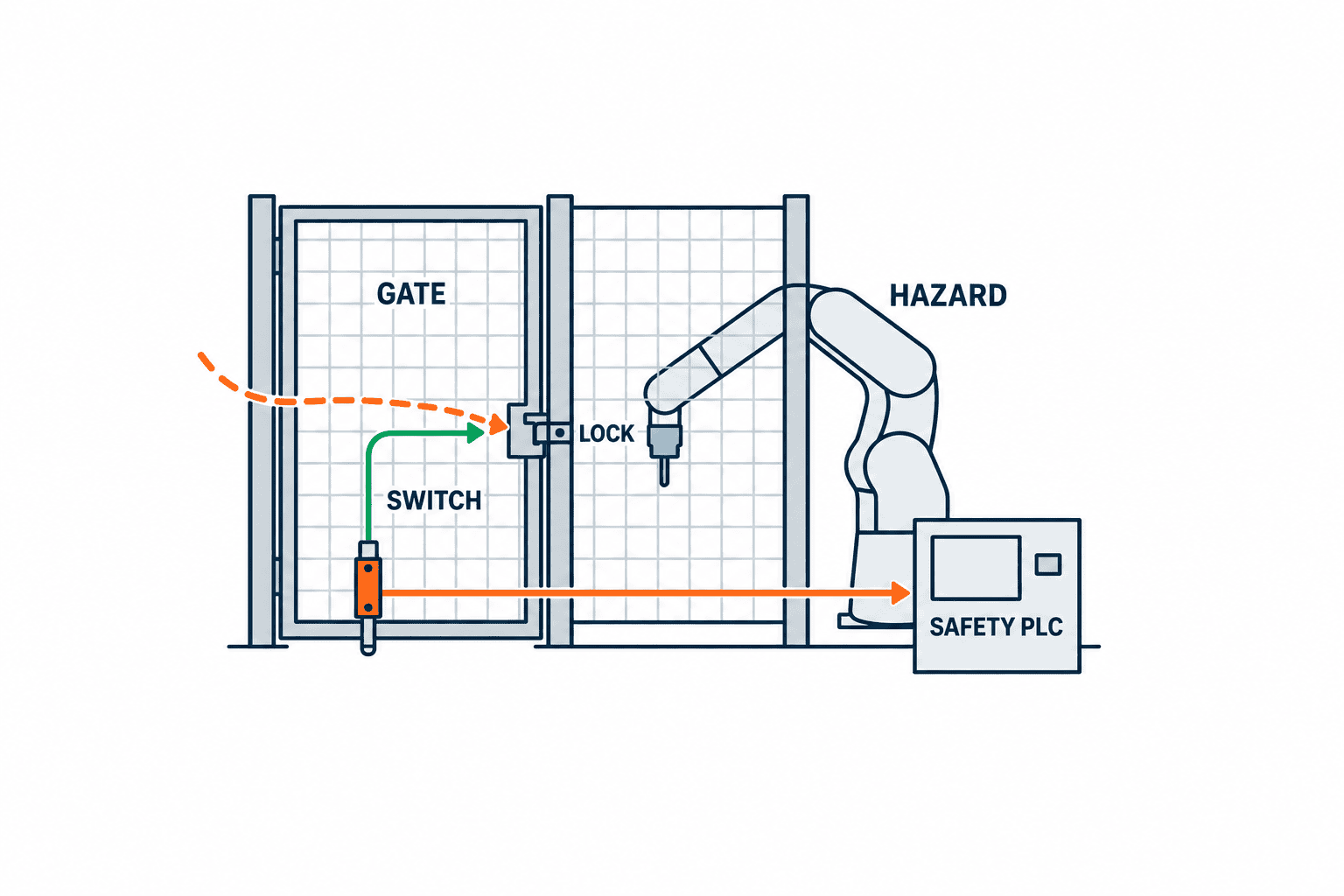
“Safety door switch” and “interlock switch” broadly describe devices that detect a movable guard and feed a stop or start-inhibit safety function. A guard-locking device also holds the guard closed. Detection of the closed position and retention of the guard are distinct requirements and should be written separately. With an interlock alone, opening the door requests a stop and an open door inhibits hazardous operation. If a worker can reach moving parts while they coast, or while pressure or gravity creates a hazard, that stop request may be insufficient. Guard locking can prevent opening until the hazard is gone. Conversely, if the hazard reliably ceases before it can be reached, an unlocked interlock may be appropriate. A lock chosen simply because it seems more protective may complicate escape, cleaning and changeover.
ISO 14119:2024 addresses design and selection of guard interlocking devices and reasonably foreseeable defeat. ISO 14120:2015 addresses guard design and construction; ISO 13855:2024 includes positioning of interlocking guards relative to human approach. Begin with the machine’s risk assessment and applicable machine-specific standards. Mentioning international standards does not, by itself, establish compliance with Thai law.
| Decision | Interlock without locking | Guard locking | Evidence to retain |
|---|---|---|---|
| Hazard after opening | Confirm it ceases before access | Keep gate closed until hazard ceases | Measured stop, access path, hazards |
| Full-body entry | Design restart and presence measures | Also design escape and rescue | Entry patterns and visibility |
| Power loss | Check machine stop behavior | Check lock retention and release too | Device specification and risk assessment |
| Process protection | Stopping may suffice | Locking can also protect workpieces | Distinguish process and personnel functions |
Compare stopping time with access time under matching conditions
Do not select a lock from an assumed stopping time or a rough fence distance. Measure from the stop request until the relevant hazard has ceased under adverse foreseeable operating conditions. A drive “stopped” bit does not prove that a blade, roller, workpiece, pressure or suspended load is safe. Record load, speed, temperature, brake condition, supply conditions and which hazard was measured. Examine gate opening direction, opening width and actual route to each hazard. A person reaching through a partly opened gate differs from a person walking through it. Consider other apertures and routes around the guard. Apply ISO 13855:2024 to the actual geometry; this article cannot prescribe a universal number of seconds or distance.
If the hazard may remain when a person can reach it, evaluate guard locking or another measure that prevents access. The unlock permission must be tied to an engineered indication that the relevant hazards have ended, not an arbitrary timer alone. Where several drives share one enclosure, measure and map each relevant source, rather than using one representative motor. Omron explains this comparison of stopping and access in its selection guidance, but a part selection still depends on the complete machine safety function.
Types of safety door switches and the real selection criteria
Tongue-actuated mechanical switches offer a clear physical actuation method. Hinge switches use gate rotation. Non-contact devices may suit gates with some movement or washdown, subject to their specified sensing range and environment. Coded actuators or RFID devices can make simple substitution more difficult. None of these labels means “defeat-proof” or establishes the required system performance. Check mounting, actuator retention, spare actuator control, gate play and access frequency.
Contact arrangement and output type must match the safety controller and its diagnostic design. Examine positive-opening contacts where applicable, dual inputs, wiring-fault detection and electronic OSSD specifications in the actual product manual. Wiring many doors in series can hide faults or alter diagnostic coverage. Validate the entire circuit and the manufacturer’s permitted connection arrangements.
| Device approach | Suitable question | Main limitation to investigate |
|---|---|---|
| Mechanical actuator | Is alignment stable and secure? | Wear, misalignment and spare-key defeat |
| Hinge switch | Can opening be sensed at the hinge? | Hinge changes and mechanical loads |
| Non-contact coded | Are misalignment and defeat concerns significant? | Sensing distance, pairing and replacement setup |
| Guard locking | Can hazards remain after a stop request? | Release logic, power loss, escape, holding strength |
| Trapped key | Must several isolation points and access gates follow an order? | Key control, duplicates, loss and exceptional work |
The published ISO 14119:2024 scope includes trapped-key interlocking devices and systems. They can enforce an order among isolation and access points, but transferring a key does not remove residual energy. Define isolation, verification, release, entry and restart for the machine. If personnel can enter the enclosure, consider escape, presence and unexpected restart separately.
Choose the locking principle by power failure, faults and escape
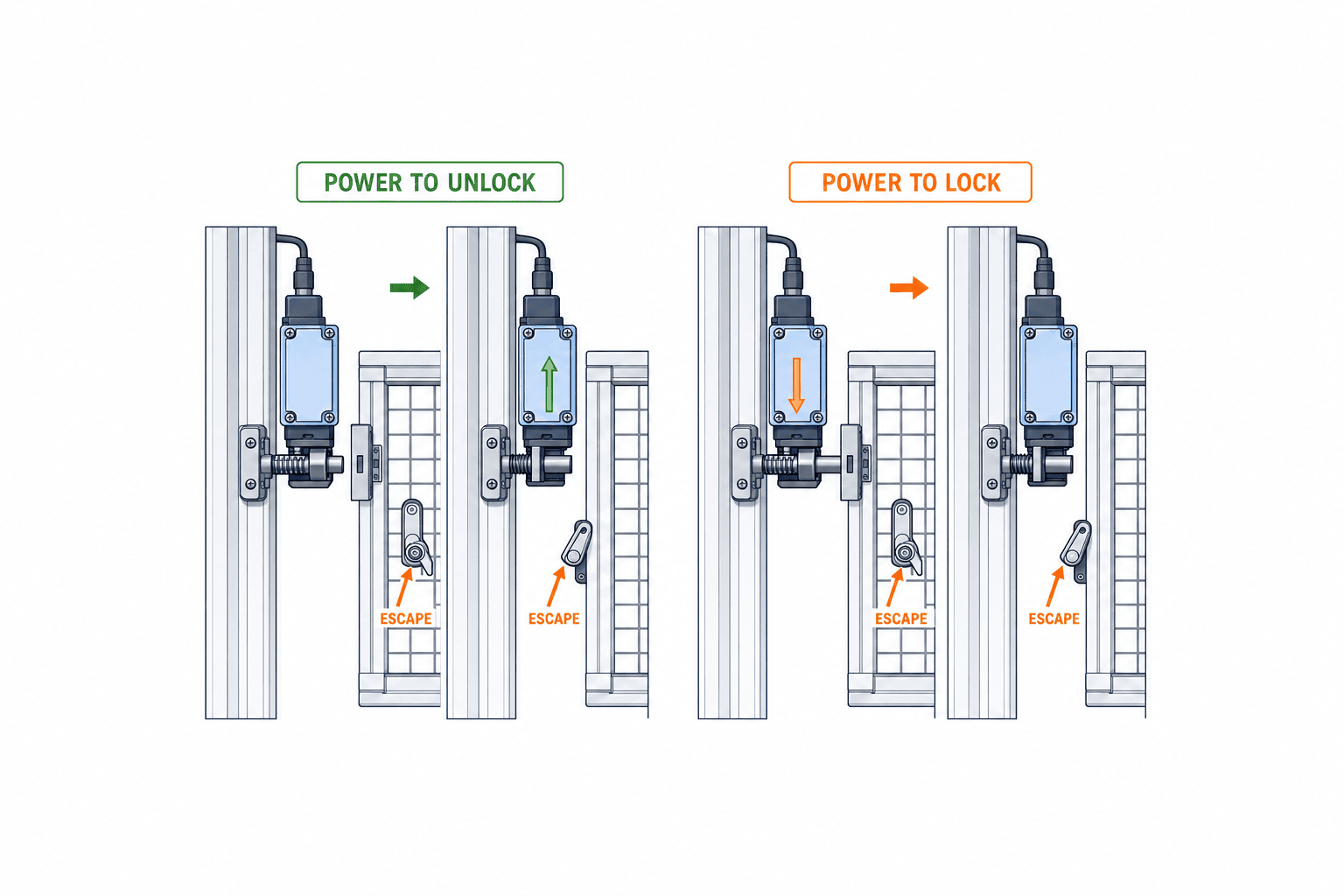
Distinguish power-to-lock from power-to-unlock. In Omron’s guidance, power-to-unlock is generally preferable for personnel protection, while power-to-lock may be used following a suitable risk assessment. This is manufacturer guidance, not a universal part-number rule. Evaluate what power loss means for hazardous motion, potential entrapment, fire and rescue, as well as whether locking serves personnel or process protection.
A catalogue holding-force figure alone does not prove a safe gate. Evaluate gate size, foreseeable forces, impacts, vibration, panel stiffness, hinges and mounting brackets. Do not use the switch body as a gate stop unless the manufacturer explicitly designs it for that function. Compare environmental ratings with actual temperature, oil, dust and washdown conditions. Distinguish auxiliary release, external emergency release and inside escape release. An outside tool-operated auxiliary release cannot substitute for a means of escape by a person trapped inside. Test the location, visibility and restart state after every release method.
Reduce the incentive and opportunity to defeat an interlock
Frequent nuisance stops, a long wait for access and a cleaning task that cannot be done through the intended route create pressure to bypass protection. ISO 14119:2024 addresses reasonably foreseeable defeat. Coded actuators help, but the design must also consider why people open the gate, how often, and whether the authorized procedure is workable. Secure actuators against casual removal, protect spare keys and choose mounting positions that discourage simple substitution without making maintenance impossible. If the door sags, correct the hinge, track or stop rather than merely increasing sensor tolerance.
Maintenance or setup requiring powered movement inside a guarded area needs a separately assessed safe mode. Define control authority, limited movement where applicable, enabling devices, operator position, exit confirmation and the protection that replaces the normal guard function. Record when and how any bypass is authorized and removed. A door log alone is not proof that a person is safe inside.
Wiring and control: component PL is not machine PL
A door switch is one input in a safety function extending through logic to contactors, drive safety functions or valves. ISO 13849-1:2023 gives methods for designing and integrating safety-related control parts; it does not prescribe a required PLr for every application. Derive the required performance from the machine risk assessment and evaluate the complete function. Two contacts do not automatically create a redundant circuit. Analyze common wiring damage, welded contacts, lost actuators, incorrect parameters, supply faults and output-device failures, and what diagnostics detect them.
“Gate closed”, “lock engaged”, “hazard stopped” and “unlock permitted” are different states. A control system that runs on a gate-closed signal without monitoring a required guard lock can miss a failed lock. A locked gate does not make another open access point safe. Document start, opening, closure, locking, stop request, stop confirmation, release, faults and power restoration as distinct states. Ordinary PLC display of a safety status is useful for operation, but cannot replace the designed safety function. For end-to-end validation, see our safety PLC guide. Our IO-Link Safety selection guide also explains why a communication technology does not certify the entire machine.
Put the safety requirements into the RFP before asking for a part number
“Supply safety switches” allows each bidder to assume a different gate, locking mechanism, wiring and test scope. Provide the hazard and stop method, gate drawings, access tasks, environment, opening frequency, required safety functions and existing controller boundary. State whether stopping time is already measured or belongs in the supplier’s scope. If PLr or SIL is stated, attach the risk assessment and specify the exact function. A number without a function is not an adequate procurement requirement.
| RFP field | Buyer input | Supplier deliverable |
|---|---|---|
| Gates and hazards | Layout, gate IDs, access paths and tasks | Gate-to-hazard map and mounting layout |
| Hazard cessation | Stop method and available measurements | Stop-time plan and unlock logic |
| Device selection | Environment, cycle and maintenance needs | Model data, drawings and wiring |
| Locking and escape | Power loss, entry and rescue scenarios | Lock principle and release methods |
| Safety control | Existing relay/PLC, outputs and PLr | Safety-function list, calculation and fault analysis |
| Handover | Document languages and trainees | FAT/SAT records, as-built files and maintenance guide |
Separate hardware, actuators, handles, escape devices, cabling, panel changes, software, stop measurement, tests, training and spares in the quotation. Assign responsibility for repairs to an existing weak gate or fence. For an imported line in Thailand, align English drawings with Thai work instructions and specify local spare parts and first response. The device price is only one element of the delivered safety function.
FAT and SAT: test the design, then the installed machine
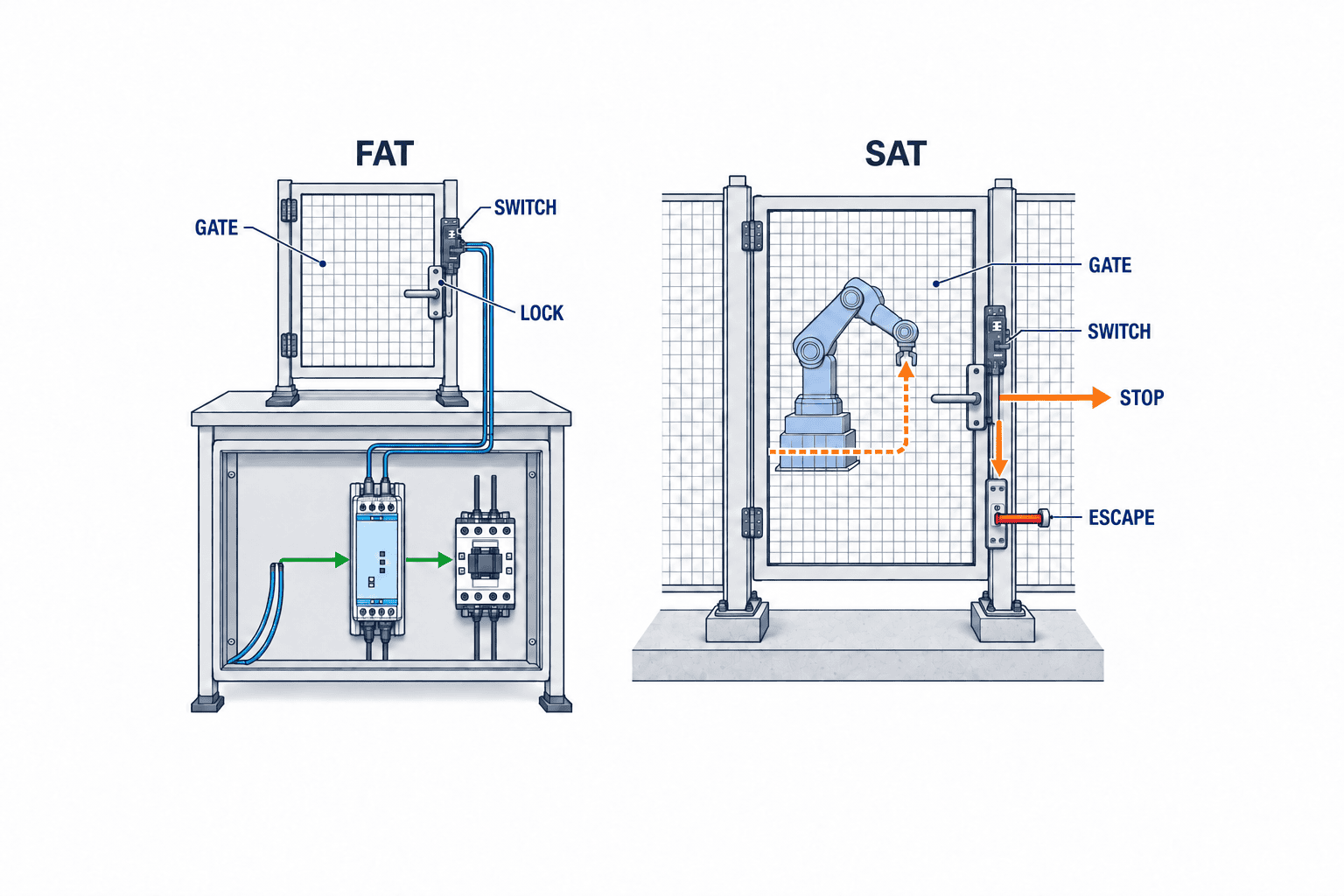
At FAT, verify part numbers, mounting, wiring, state transitions, safe fault simulations, release methods and documents at the supplier. Record limits where the actual load or access geometry cannot be reproduced. At SAT, verify installed alignment, gate play, cable protection, all relevant stopping behavior, actual routes to hazards, power failure and restoration. Changes to the door position or stopping performance after FAT require renewed evaluation.
ISO 13849-2:2012 covers validation of specified safety functions and achieved category and PL by analysis and testing. One demonstration that “opening the gate stops the machine” is not enough. Keep expected and actual results, test conditions, fault responses, open issues and approvals. Agree on simulations or fixtures for dangerous faults instead of creating unsafe real faults.
| Scenario | FAT | SAT addition |
|---|---|---|
| Gate operation | Stop request, start inhibit and manual restart condition | Actual alignment, vibration and reach path |
| Locking | Closed/locked/released transitions | Hold until hazards cease and actual release access |
| Faults | Safe simulation of broken wire, short and channel/output fault | Installed wiring diagnostics and recovery |
| Power | Loss and restoration state | Site supply and residual hazards |
| Escape | Inside release and reset | Usable from actual internal locations |
| Documents | Models, wiring, test and settings | As-built package, spares and training |
Make inspection and change control part of selection
People touch safety gates frequently. Hinges loosen, stops deform, cables pinch, actuators wear and washdown enters enclosures. Inspection must cover physical condition and actual stopping, locking and emergency release, not just an HMI “closed” indication. Set inspection and replacement criteria from the manufacturer instructions, cycle frequency and site environment. Keep exact model, paired actuator, coding setup, release keys and configuration in the spare-parts register. After replacement, revalidate the relevant safety function and fault behavior. Moving the gate, changing brake components or editing safety logic can alter the original stop-and-access assessment.
Record why gates are opened: cleaning, jam removal, quality check, changeover or repair. Each pattern suggests a different design improvement. If workers find the authorized route impractical, address the access method and equipment layout with them. Simply blaming operators will not remove the incentive to bypass a troublesome gate.
Examples by machine type
In a robot cell, identify every hazard reachable through the gate: robot, end effector, conveyor, fixture, pneumatic grip and adjacent equipment. A robot “stopped” indication is not proof a suspended workpiece cannot fall. Map each gate to all hazards and inhibit automatic restart after closure. In packaging or conveying, consider residual roller motion, falling products and heated parts even after the drive stops. Separate a lock used for product protection from one used as a personnel safety function. For a retrofit, compare actual wiring with drawings and check the existing brake, contactors and gate stiffness. Replacing one old sensor with a new one does not complete the retrofit if the rest of the stop function cannot meet the requirement.
A decision sequence for the selection meeting
Give each gate an ID and list each hazard a person can reach through it: robot axes, grippers, conveyors, pneumatic clamps and hot surfaces can have different stopping behavior. Map operation, setup, cleaning, jam removal, repair and abnormal recovery to the actual access route. A door opened every cycle may require a different arrangement from a maintenance-only gate. Plan stopping measurements for each relevant hazard and compare them with the shortest access path. If data are missing, put measurement in the quotation rather than selecting by assumption. Then determine whether locking is needed, which power-loss behavior is appropriate, whether a person can remain inside, and how predictable defeat will be reduced. Finally match the switch outputs to the safety logic and final stop elements and define FAT/SAT acceptance evidence. Record why an unlocked alternative was rejected, who owns missing measurements and what future changes trigger reassessment.
Turn failure behavior into explicit tests
Normal opening-and-stopping is only one case. Analyze one input wire broken, a short affecting both channels, an actuator coming loose, or a contradiction between gate position and lock status. Safe test terminals, simulation and analysis may be more suitable than creating a dangerous fault on the installed machine. For each case, record the expected indication, stop, start inhibit and deliberate recovery. An alarm reset alone must not unexpectedly restore hazardous output. Distinguish a complete cabinet power loss, loss of switch supply alone, pneumatic power remaining and power returning while the gate is open. The actual lock behavior depends on the product and wiring; external rescue and inside escape are separate checks. Closing the gate after restoration should not automatically restart hazardous motion.
Tie “hazard stopped” to a physical state, not merely to the name of a drive command. If safe speed or standstill monitoring is used, include its sensor, wiring, settings and fault response in the safety function. Reassess measurements when brake wear, overload or a changed process recipe can alter stopping. For trapped-key systems, test exceptions such as a lost or duplicate key, failed isolation indication and two people entering through different gates. Key possession does not equal safe isolation of electrical, pneumatic or gravity energy. FAT can check the control sequence; SAT must check real key handling and movement through the machine. Judge tests by which gate moved, when each hazard ceased, when the lock released and how faults were signaled. Close deviations with an approved correction and retest, and train maintenance personnel separately on normal recovery and emergency release.
Safety door switch selection FAQ
What differs between a safety door switch and a guard-locking switch?
A door switch broadly monitors guard position as an input to stop and start inhibition. A guard-locking switch additionally retains the gate. Specify position monitoring, lock monitoring and retention until hazards cease as separate requirements; the lock component alone does not complete the safety function.
Is guard locking required for every gate?
No universal rule applies. Measure stopping, access and residual hazards for the machine. Locking is an important candidate where motion or other hazards remain reachable after a stop request. Do not apply a generic number of seconds without risk assessment.
Does high coding prevent every bypass?
It reduces simple substitution, but also manage mounting, wiring, spare actuators, authorized access and maintenance. A badly aligned gate remains troublesome even with a highly coded sensor.
May I wire several door switches in series?
Only after checking manufacturer limits, fault masking, diagnostic coverage and the required performance of the whole function. Independent inputs may be needed. A successful normal opening test is not enough.
What if a person can enter behind a locked gate?
Assess entrapment and unexpected restart. Provide a suitable inside escape and rescue concept, presence or exit checks as required, and test emergency release against residual hazards. An external auxiliary release is not an inside escape measure.
What evidence should FAT/SAT leave?
Retain gate-to-hazard mapping, safety requirements, models, circuit drawings, stop measurements, normal/fault/power/escape tests, open items and approvals. FAT tests the supplier setup; SAT tests the installed machine. A component PL label is not a validation record for the machine.
Conclusion
Select a safety door switch by connecting gate detection to stop time, human access, locking, power-loss behavior, escape, resistance to defeat, wiring diagnostics and restart control. The RFP should identify each gate and hazard and require measurable acceptance evidence. FAT confirms the designed behavior; SAT confirms behavior on the actual installed machine. The component data sheet is a starting point; the machine-level safety function needs its own evidence.
If you are planning a new safety gate or a retrofit in a Thai factory, contact TOMAS TECH. We can help organize the missing stop measurements, drawings, RFP scope and FAT/SAT plan before you commit to a device model.
Sources
- ISO 14119:2024: guard interlocking selection
- ISO 14120:2015: guard design
- ISO 13855:2024: safeguard positioning
- ISO 13849-1:2023: safety-related control design
- ISO 13849-2:2012: validation
- Omron: four guard-locking selection questions
- Pilz: guard-locking selection
- Rockwell Automation: safety switch technical data


