


Conveyor speed detection, feed-length measurement, positioning on automated machines, rotation detection on motor shafts: encoders are used all over a plant. Yet when one fails, we often hear the same complaints. “We can’t get the same model.” “We can’t tell whether the model in the system integrator’s (SIer’s) quote is appropriate.” “Every line uses a different maker and model, so we can’t keep a full set of spares.” Rotary encoder selection looks as if it should only take a comparison of catalog resolutions, but in practice it involves the receiving equipment, the wiring and even the recovery procedure.
This article makes one argument. If you select an encoder on “resolution” alone, you will get it wrong.
- Raising the resolution raises the output frequency at the same speed, so you run into the limits of the receiving input (high-speed counter) and of the encoder’s own maximum response frequency. The electrical speed limit and the mechanical permissible speed are separate limits, and the practical limit is the smaller of the two
- “CPR”, “pulses” and “counts” are defined differently by different makers, and whether 4x multiplication is applied makes a factor-of-4 difference. Make the specification state the definition
- The output type (open collector, voltage output, line driver, push-pull, etc.), cable length and noise countermeasures are decided together with the receiving equipment. Cable length guidelines differ by maker, so do not generalize them into a single number
- Whether homing is needed after a power loss (incremental) or the position is retained (absolute single-turn or multi-turn) is decided from the equipment’s recovery procedure and from safety
- Serial interfaces (SSI, BiSS, EnDat, etc.) have a relationship between clock rate and cable length, and the options are determined by what the drive or controller supports
- Environment (oil, dust, condensation, vibration), IP rating, shaft load, mounting method and coupling are checked against site conditions
- Model standardization, spare parts and preparation for end of production make a large difference to downtime when an encoder fails
That is why it matters for the buyer to have the assumptions written into the RFP (request for proposal) and to measure them in the FAT (factory acceptance test) and SAT (site acceptance test).
Below, for production engineering, equipment design, maintenance and procurement staff at Japanese-affiliated plants in Thailand (Chonburi, Rayong, Ayutthaya, Samut Prakan, Pathum Thani, etc.), we work through encoder types, the eight selection steps, resolution, response frequency, output type, wiring, serial interfaces, environment, mechanical mounting, functional safety, replacement and end of production, how to read maker documents, the RFP, FAT/SAT, and cost and benefit, in that order.
Note that this article does not recommend or rank any maker’s products. Maker figures depend on the definitions and conditions in each document and were not measured under the same conditions. The model calculations later in the article use hypothetical figures prepared for this article and are not a quotation.
What Is a Rotary Encoder: Applications and Configuration
A sensor that turns rotation into an electrical signal
A rotary encoder is a sensor that converts the rotation of a shaft into an electrical signal. Its main uses in a plant fall into three groups.
- Speed detection: measuring the speed of conveyors, rolls and motor shafts
- Position detection: positioning on automated machines, indexing on index tables, and feedback for servo motors
- Length measurement: measuring the feed length of film, wire or sheet from the rotation of a feed roller
For servo motors, there are encoders of a type built into the motor, which are selected together with the drive. Inverter-driven motors, driven shafts of conveyors, measuring rollers and the like, on the other hand, can be fitted afterwards with a shaft-type or hollow-shaft encoder. How to decide between servo control and inverter control is covered in “Servo Control vs Inverter Control 2026 | 4 Boundaries That Decide the Choice“. This article mainly covers shaft-type and hollow-shaft encoders fitted afterwards, and touches on built-in motor feedback where necessary.
Overview of the types

Encoders are easier to sort out when classified along the following three axes.
| Classification axis | Main types | What matters in selection |
|---|---|---|
| How position is obtained | Incremental / absolute single-turn / absolute multi-turn | Behavior after power loss, whether homing is needed |
| Detection method | Optical / magnetic (also capacitive, inductive, etc.) | Resolution, environmental robustness, magnetic influence |
| Output and communication | Open collector / voltage output / line driver (RS-422) / push-pull / serial (SSI, BiSS, EnDat, etc.) / fieldbus and IO-Link | Receiving equipment, cable length, noise |
According to the installation and wiring guide of EPC (Encoder Products Company) in the US, an incremental encoder outputs a square wave proportional to rotation, while an absolute encoder outputs a unique code word for each shaft angle. According to the same guide, a quadrature encoder outputs two channels, A and B, offset by 90 electrical degrees, and the direction of rotation is determined by which one leads. The Z channel (index) is a pulse that occurs once per revolution at the same mechanical position.
Absolute vs Incremental Encoder: The Differences
What happens after a power loss
Put simply, the difference between an absolute encoder and an incremental encoder is “whether the current position is known after the power has been off”.
| Aspect | Incremental | Absolute single-turn | Absolute multi-turn |
|---|---|---|---|
| What it outputs | Pulses proportional to rotation (A, B and Z channels) | A unique value for each angle within one revolution | Angle within one revolution plus number of revolutions |
| After power loss | Position is unknown. Homing is required | Position within one revolution is known | Position is known over a range beyond 360° |
| Example applications | Speed detection, length measurement, positioning where homing is possible | Angle detection completed within one revolution | Positioning over multiple revolutions (ball screw axes, etc.) |
| What to check | How the home position is taken, use of the Z channel, the receiving counter | Number of bits, communication method | How the revolution count is retained, number of bits, communication method |
With an incremental encoder, the receiving counter counts pulses to obtain the position, so when the power drops due to an outage or emergency stop, the system no longer knows where it is. Recovery requires a homing operation. Whether the machine is allowed to move during homing, whether it will interfere with workpieces or fixtures, and whether operators can follow that procedure are inputs to the choice of type.
An absolute encoder knows its position as soon as power is applied. A multi-turn encoder also counts revolutions, so according to POSITAL’s explanation it can measure over a range beyond 360°. For how to commission and accept servo control, “Servo Control Procurement and FAT/SAT Guide for Thailand Plants in 2026” is also useful.
Multi-turn encoders differ in “how the revolution count is retained”
With multi-turn absolute encoders, how the revolution count is kept when the shaft is turned while external power is off differs from product to product. The documents we checked described the following methods (all are vendor claims).
- POSITAL: counts revolutions without batteries or gears, using energy harvesting based on the Wiegand effect. It says the method generates voltage pulses regardless of rotational speed (even near zero) to power the counting circuit, and that it has been in use since 2005. The company points out that batteries have a limited life, are heavy and contain hazardous substances, and that gear units are large, complex, expensive and vulnerable to shock and vibration
- Kübler: describes the Sendix M3688 IO-Link on its product page as an electronic multi-turn encoder that, “thanks to Energy Harvesting technology, uses neither gears nor batteries”
- Nikon: announced the MAR-M700MFA on November 20, 2023, describing it as the “world’s first” “multi-turn batteryless absolute encoder equipped with an all-solid-state battery” (Nikon’s own claim). It is a kit type for building into servo motors, not a general-purpose shaft-type encoder
Even under the same “batteryless” label, the principles differ. The reliable approach is to confirm in the specification which method, including battery-based ones, is used to retain the revolution count, and to have the maker write down the maintenance procedure (whether replacement is needed and how it is done).
Number of bits and number of positions
Absolute resolution is expressed as the number of unique positions per revolution, and is often written in bits. The calculation works out as follows.
- 14 bit = 2¹⁴ = 16,384 positions/revolution. 360° ÷ 16,384 ≈ 0.022° (single-turn resolution of the Kübler M3688, product page)
- 18 bit = 2¹⁸ = 262,144 revolutions (same product, multi-turn part)
- 27 bit = 134,217,728 divisions, 16 bit = 65,536 revolutions (maximum values for the Nikon MAR-M700MFA, 2023 release)
More bits means the position is known more finely, but it is meaningless if it exceeds the number of bits the receiving side (controller, drive) can handle. POSITAL writes that SSI controllers are often limited to 13 bits single-turn (vendor claim).
The 8 Steps of Encoder Selection
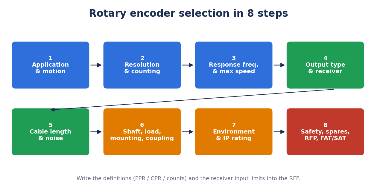
We have split encoder selection into eight steps in the order decisions should be made. Deciding from the top down makes rework less likely later.
| Step | Content | Main decisions |
|---|---|---|
| 1. Application & motion | Whether it is used for speed, position or length measurement. Speed range, behavior after power loss | Incremental or absolute, single-turn or multi-turn |
| 2. Resolution & counting | The required fineness of angle or length | Definition of resolution (PPR, CPR, bit), multiplication setting |
| 3. Response frequency & speed | Whether the output frequency exceeds the limit at maximum speed | Electrical speed limit, mechanical permissible speed, input frequency of the receiving side |
| 4. Output type & receiver | Whether the output suits the input circuit of the receiving side | Open collector, voltage output, line driver, push-pull, serial |
| 5. Cable length & noise | Wiring length and route, distance from noise sources | Cable type, shielding, wiring route, supply voltage |
| 6. Mechanical: shaft, load, mounting, coupling | Shaft diameter, shaft load, mounting method | Shaft type or hollow shaft, coupling, position of pulleys and gears |
| 7. Environment & IP | Oil, dust, condensation, vibration, temperature | Detection method, protection rating, operating temperature and humidity |
| 8. Safety, spares, RFP, FAT/SAT | Whether it is a safety application, conditions for replacement and procurement | Whether certification is needed, standard models, spare parts, acceptance test items |
The following sections go through what to check at each step.
How to Determine Encoder Resolution: Differences Between PPR, CPR, Counts and Bits
Work backwards from the “required fineness”
Encoder resolution is first decided from “how finely do we need to know”. For a measuring roller, that is the feed length per pulse; for positioning, it is the required angular fineness. However, as the next section shows, raising the resolution more than necessary lowers the speed limit. It is important not to choose on the basis that “bigger is safer”.
“CPR” has two meanings that differ by a factor of 4
The units of resolution are named, and mean, different things depending on the maker.
| Term | Meaning (source) |
|---|---|
| P/R, PPR | Pulses per revolution. Omron and Autonics write “P/R”, Same Sky (formerly CUI Devices) writes “PPR”. Same Sky explains PPR as the number of high pulses output on channel A or channel B per revolution |
| CPR (Counts per Revolution) | According to Same Sky, in many cases this refers to the number of states from quadrature decoding of channels A and B (PPR × 4) |
| CPR (Cycles per Revolution) | EPC uses “CPR = Cycles Per Revolution” with the same meaning as PPR. Same Sky also warns that some makers use it in the Cycles sense, which differs by a factor of 4 |
| LPR (Lines per Revolution) | According to Same Sky, the same as PPR |
| bit | The number of positions per revolution for an absolute encoder. EPC writes “bits or counts per revolution” |
For example, if a 2,000 P/R incremental encoder is multiplied by 4 on the receiving side, the result is 2,000 × 4 = 8,000 counts/revolution, and 360° ÷ 8,000 = 0.045°/count (based on Same Sky’s definition “CPR = PPR × 4”). Even with the same number “2,000”, the actual fineness differs by a factor of 4 depending on whether it is a pulse count or a count after 4x multiplication.
The “1 to 100,000 CPR” of the 36RT/H Accu-CoderPro® that EPC announced on August 27, 2026 also has to be read using EPC’s definition (Cycles). When comparing it with another maker’s PPR, align the definitions first.
Write the receiving-side multiplication setting into the specification too
With an incremental encoder, the size of one count changes depending on whether the receiving counter is used at 1x, 2x or 4x multiplication, even with the same encoder. In the RFP, ask for the unit of the encoder’s resolution (PPR, CPR = Cycles, CPR = Counts, bit) and the receiving-side multiplication setting to be stated together. When modifying existing equipment, checking which definition the “travel per pulse” constant in the program was built on also prevents mix-ups at replacement.
Maximum Response Frequency and the Speed Limit
Electrical and mechanical limits are separate
Encoder response frequency is the point where selection most often goes wrong. An encoder has the following two limits.
- Electrical limit: the speed determined by the maximum frequency the encoder’s output circuit can respond to (maximum response frequency). Omron calls it “Maximum electrical response speed” and Autonics calls it “Max. response revolution”
- Mechanical limit: the permissible speed determined by mechanical constraints such as the bearings. Omron calls it “Maximum permissible speed” and Autonics calls it “Max. allowable revolution”
The electrical speed limit is calculated with the following formula, which appears in Omron and Autonics documents.
Electrical speed limit (rpm) = maximum response frequency (Hz) ÷ resolution (P/R) × 60
Omron’s document states that above this speed the encoder will not respond electrically. The practical limit is the smaller of the electrical and mechanical limits. Autonics’ product page also carries a note: “When selecting the resolution, make sure the max. response revolution is equal to or lower than the max. allowable revolution.”
Calculation example (Model A)
Using the values in each maker’s documents, the calculation works out as follows.
| Condition | Calculation | Electrical limit | Mechanical limit | Practical limit |
|---|---|---|---|---|
| Autonics E50S8-5000-6-L-5-C (line driver, product page values) 5,000 P/R, 300 kHz | 300,000 ÷ 5,000 × 60 | 3,600 rpm | 5,000 rpm | 3,600 rpm (set by the electrical side) |
| A model with 100 kHz maximum response frequency at 2,000 P/R | 100,000 ÷ 2,000 × 60 | 3,000 rpm | Depends on the model’s permissible speed | 3,000 rpm if the mechanical limit is higher than this |
| A model with 100 kHz maximum response frequency at 1,000 P/R | 100,000 ÷ 1,000 × 60 | 6,000 rpm | Depends on the model’s permissible speed | Both limits coincide if the model’s mechanical limit is 6,000 rpm |
The Autonics E50S8-5000-6-L-5-C can mechanically turn up to 5,000 rpm, but at 5,000 P/R the electrical side reaches its limit first at 3,600 rpm. In the 100 kHz model example, raising the resolution from 1,000 P/R to 2,000 P/R lowers the electrical speed limit from 6,000 rpm to 3,000 rpm. Doubling the resolution halves the electrical speed limit.
Note that an older Omron datasheet (CSM_E6B2-C_DS_E_4_1, a copy hosted by a distributor) states that the maximum response frequency of the E6B2-C is 100 kHz or 50 kHz depending on the model. Because of merged cells in the table, this article does not identify which model has which value. Check the value for the model you actually use in the latest datasheet.
Check the input frequency of the receiving side as well
Even if the encoder side has margin, counts will be missed if the input frequency limit of the receiving side (a PLC high-speed counter, the encoder input of an inverter or drive, etc.) is exceeded. Calculate the output frequency at maximum speed, and have it shown in figures at the RFP stage that it is below the limits of both the encoder and the receiving side. Multiplication to get finer counts is done by the receiving side, so the encoder’s output frequency is calculated from the pulse count before multiplication.
Encoder Output Type and Receiving Equipment
Output type names differ by maker
The encoder output type is the form of the encoder’s output circuit. Even for the same kind of circuit, makers use different names. Omron writes “NPN open collector”, “voltage output (NPN output)” and “line driver (RS-422A equivalent, AM26LS31 equivalent)”; Autonics writes “Totem pole”, “NPN open collector” and “Line Driver”; Pepperl+Fuchs writes “Push-Pull (a combination of NPN and PNP)”. Dynapar sometimes refers to outputs by driver IC part numbers such as 7272 and 4469. “HTL” and “TTL” are customary terms for signal levels, not names of output circuits. Check the voltage range in the datasheet for each model.
Characteristics of each type
Lining up the descriptions in each maker’s documents gives the following (all are vendor claims).
| Output type | Maker descriptions | Matching receiving side | Points to check |
|---|---|---|---|
| Open collector (NPN / PNP) | Dynapar: “Simple in structure and inexpensive, an output that only sinks current. Suited to short-cable applications; not suited to long cables or noisy environments” | An input circuit matching sink / source | NPN or PNP, input format of the receiving side, wiring length |
| Voltage output | The Omron E6B2-C has “voltage output (NPN output)” models (older datasheet) | A counter with voltage input | Matching of supply voltage and input voltage |
| Push-pull | Pepperl+Fuchs: “An output combining NPN and PNP. Better rise time and noise immunity than open collector, with no external circuitry needed. For medium switching frequencies” | Whether it suits the input format of the receiving side | Supply voltage, frequency, wiring length |
| Line driver (RS-422) | Pepperl+Fuchs: “A symmetrical (differential) interface, recommended when high noise immunity or long wiring is required”. Dynapar: “Actively drives the output both high and low, and can handle long cables” | RS-422 receiver (differential input) | Whether the receiving side has a differential input, voltage drop with a 5 V supply |
| Serial (SSI, BiSS, EnDat, etc.) | Sends the position value digitally (next section) | A master that supports the same protocol | Protocol, bit length, code, clock |
Line driver or open collector: which to choose
The three decision criteria are wiring length, noise environment and the input circuit of the receiving side. Dynapar says that differential signals and shielded twisted-pair cable are important in long-distance, high-noise environments. On the other hand, if you choose a line driver output, you first need to confirm whether the receiving side has an RS-422 receiver (differential input). Omron writes that when extending a line driver, twisted-pair cable and an RS-422A receiver should be used. The right order is to check the input specification of the receiving side first, not just the encoder, and then decide the model.
Cable Length, Noise and Wiring
Cable length guidelines differ by maker
There is no single answer to “how far can an encoder cable be extended”. The guidelines in the documents we checked are as follows.
| Source | Open collector | Line driver |
|---|---|---|
| Omron E6B2-C (precautions in the older datasheet) | Do not extend beyond 2 m | Use a line driver model when exceeding 2 m (max. 100 m) |
| Dynapar FAQ (May 24, 2021) | About 35 ft (≈ 10.67 m) | About 100 ft or more with differential input (≈ 30.48 m or more) |
| Dynapar white paper (no publication year stated) | Short-cable applications (generally under 30 ft, ≈ 9.14 m) | Around 50 to 75 ft with 7272-type drivers, around 100 to 300 ft with 4469-type |
Feet are converted at 1 ft = 0.3048 m (100 ft = 30.48 m, 35 ft = 10.67 m, 30 ft = 9.14 m). Dynapar’s values are guidelines described as “typical” or “in the neighborhood of” and assume Dynapar products. Omron’s values concern a single model, the E6B2-C. Do not treat any of these numbers as “the general limit for encoders”. Decide based on the value in the datasheet of the model you use and on the conditions of the receiving side.
What happens when you extend the cable
Omron’s older datasheet notes that the longer the cable, the more the residual voltage rises due to conductor resistance and capacitance between conductors, distorting the waveform, and that extension lengthens the rise time and affects the phase difference characteristics of channels A and B. It also states that line driver models are powered at 5 V and that there is a voltage drop of about 1 V at 100 m. Dynapar likewise explains that a longer cable picks up noise more easily (line capacitance, antenna effect, power loss).
Wiring principles (maker recommendations)
The wiring precautions given by the makers are as follows.
- Keep away from noise sources: Dynapar recommends not routing wiring near AC motors, arc welders, AC power lines or transformers. EPC writes that wiring should take the shortest route and be run in a dedicated metal conduit or kept at least 12 inches away from other wiring
- Twisted pair and shielding: Dynapar recommends twisted pair for a signal and its complement, and shielding for every signal
- Output voltage: Dynapar says to use the higher end of the usable output voltage range (for example, 24 V for a 5 to 24 V output)
- Shield grounding: EPC recommends grounding the shield at the controller / counter side and not connecting it at the encoder side (because grounding at both ends can cause ground loops). This is EPC’s recommendation, and some makers or equipment may specify a different grounding method. Follow the instructions of the maker of the equipment you use
- Power supply: EPC says that many electrical failures are caused by poor supply voltage or poor regulation, and strongly recommends surge protection
Power ON/OFF and false pulses
Omron’s older datasheet states that false pulses occur at power ON/OFF, so connected equipment should be used only 0.1 s or more after the encoder is powered on, and use of connected equipment should stop 0.1 s or more before the power is turned off. It also cautions that stopping near a signal edge can cause miscounting, so an up/down counter should be used. The same document states that an inrush current of about 9 A flows for about 0.3 ms at power-on, which also bears on how the power supply capacity and protection are chosen. Whether such countermeasures are included in the sequence is an item to check at FAT.
Serial Interface and Fieldbus Encoders
Even with “the same name”, align the contents of a serial interface
Absolute encoders often send the position value over a serial interface. The main ones are summarized below within the scope of the documents we checked (all are vendor claims or industry association documents).
| Interface | What we could confirm | Source (date) |
|---|---|---|
| SSI | The clock is driven by the master (controller) and the data line by the slave (sensor). The position value is sent MSB first. Minimum pause time is 20 µs. Data representation is not standardized across makers (binary left-justified, Gray code, etc.). Physical layer is EIA-422 (RS-422) | POSITAL SSI explanation (accessed October 2026) |
| SSI (EPC products) | The master must correctly set the data word length, clock rate and data format (Gray / binary). The master waits at least 30 µs before sending the next clock. Standard products have a maximum clock of 500 kHz, up to 2 MHz as a custom option | EPC TB-529 (accessed October 2026) |
| EnDat 2.2 | HEIDENHAIN’s digital bidirectional interface. Four signal lines. Compatible with EnDat 2.1. Clock 16 MHz, position value acquisition within 5 µs | HEIDENHAIN technical information (September 2011 edition) |
| BiSS (BiSS C / Safety / Line) | An open standard. Cycle time under 10 µs, daisy-chain capable, protected by CRC. BiSS Safety for functional safety, BiSS Line (one cable) for wiring reduction. Adopted by more than 650 companies | BiSS Association (accessed October 2026) |
| HIPERFACE DSL® | SICK’s purely digital motor feedback protocol. Allows a single cable between the inverter and the motor. A 2017 report states two wires, up to 100 m, adopted by more than 40 companies | SICK official site, Drives & Controls (June 6, 2017) |
| A-format® | Nikon’s communication protocol. Compliant with the EIA standard RS-485, NRZ half-duplex serial | Nikon MAR-M700MFA release (November 20, 2023) |
For SSI, POSITAL and EPC give different values for the wait time (20 µs for POSITAL, 30 µs for EPC). The names for the wait time also differ: POSITAL uses “transfer timeout (monoflop time in older documents)”, while EPC uses “pause time (tp)” and “tm”. At replacement, even if the name “SSI” is the same, you need to confirm that the data word length, Gray / binary, clock and wait time match the master’s settings.
The relationship between clock rate and cable length
With serial interfaces, the longer the cable, the lower the usable clock rate.
POSITAL gives the following values as a guide to the maximum SSI clock (described “as a guide”).
| Cable length | Guide maximum clock |
|---|---|
| 13 m | 2 MHz |
| 44 m | 1 MHz |
| 85 m | 600 kHz |
| 300 m | 200 kHz |
| 750 m | 80 kHz |
Extending from 13 m to 44 m, about 3.4 times (44 ÷ 13 ≈ 3.38), halves the maximum clock. However, this relationship cannot be generalized as proportional, so use the values in the table as they are. EPC says the usable cable length is determined by the clock frequency, the SSI master, and the cable type and length, and recommends shielded twisted pair of known impedance. It also says termination to suppress reflections may be needed for long runs.
For EnDat 2.2, HEIDENHAIN’s September 2011 technical information states that without propagation delay compensation the clock is 100 kHz to 2 MHz depending on cable length, and with compensation up to 16 MHz over cable lengths of up to 100 m (but 8 MHz or less at 100 m). The compensated limit of 8 MHz at 100 m is 4 times (8 ÷ 2) the uncompensated limit of 2 MHz. The document also states that only original HEIDENHAIN cables should be used above 2 MHz, and that the adapter cable connected directly to the encoder (φ4.5 mm) is limited to 20 m, with longer runs requiring an adapter cable of up to 6 m plus an extension cable (φ6 mm). Because the document is old, the values may have changed in the current edition.
Fieldbus and IO-Link
There are also configurations in which the encoder connects directly to an industrial network.
- PROFIBUS / PROFINET: PI (PROFIBUS & PROFINET International) publishes an encoder profile (Order No. 3.162, Version 4.2, July 8, 2017). It includes definitions of safe encoder values transmitted via PROFIsafe. The full text is for members only, and we have not read it for this article
- EtherCAT: a real-time industrial Ethernet developed by Beckhoff, with the protocol published in IEC 61158. With 100BASE-TX, the distance between devices is up to 100 m (this is a general EtherCAT specification, not a value for individual encoders)
- IO-Link: according to the IO-Link Community, it is point-to-point communication over a 3-wire connection, standardized in IEC 61131-9, and is not a fieldbus. There are three communication speeds, 4.8 kBaud, 38.4 kBaud and 230.4 kBaud; it can be wired with unshielded 3-wire cable and uses M12, M8 and M5 connectors. Kübler says the Sendix M3688 IO-Link supports automatic parameter storage and firmware updates via IO-Link (vendor claim)
If you want to reduce the wiring itself on rotating or moving parts, “IO-Link Wireless Implementation for Rotating and Moving Machine Parts” is also useful. In most cases, which interface you can choose is determined by what the receiving drive or controller supports. Rather than deciding on the encoder first, it is more realistic to narrow down candidates from the control system’s compatibility list.
Optical vs Magnetic, Environment and IP Rating
Claims about optical and magnetic differ with the maker’s position
On the differences between detection methods, makers with different positions each make their own claims. They are listed here as claims.
| Company making the claim (document) | Statements about optical | Statements about magnetic |
|---|---|---|
| Same Sky (blog article, accessed October 2026) | Because it relies on a light path, it is especially vulnerable to dust, dirt and oil, and is also easily damaged by vibration, extreme temperatures and contamination during assembly | Rugged and resistant to shock and vibration, and also to oil, dirt and moisture, but susceptible to magnetic interference from motors, with a limited operating temperature range, and resolution and accuracy generally lower than optical or capacitive |
| Timken (document dated August 15, 2011) | Contamination blocking the light path interrupts the signal and causes failure. When humidity or temperature fluctuates, condensation on the rotating disc can also cause failure. The air gap is often under 0.25 mm, and it is vulnerable to shock and vibration | Unaffected by dirt, dust, oil and condensation unless the gap is filled with ferromagnetic material |
| EPC (installation and wiring guide) | Not affected by strong stray magnetic fields | ― |
Same Sky and Timken are both companies that deal in magnetic (or capacitive) encoders, and the Timken document dates from 2011. Timken itself mentions sealed optical encoders, and optical encoders with sealed construction do exist. The reliable approach is not to decide “optical or magnetic” by the name of the method alone, but to compare the protective construction, operating temperature and humidity, and mounting conditions of the actual models using catalog values. If you are considering a magnetic encoder, also check for magnetic influence from nearby motors and brakes.
Examples of IP ratings and operating environments
The following protection ratings appeared as examples of catalog values.
| Model (document) | Protection rating | Operating temperature | Operating humidity |
|---|---|---|---|
| Omron E6B2-C (older datasheet) | IP50 (IEC 60529) | −10 to 70°C (no icing) | 35 to 85% (no condensation) |
| Autonics E50S8-5000-6-L-5-C (product page) | IP50 (IP64 optional for axial cable type and axial cable connector type) | −10 to 70°C (storage −25 to 85°C) | 35 to 85%RH |
| Kübler Sendix M3688 IO-Link (product page) | IP65/IP67 | −40 to +85°C | ― |
| Kübler Sendix S5858FS3 (product page) | IP65/IP67 | −40 to +80°C | ― |
| Nikon MAR-M700MFA (2023 release) | ― | Guaranteed temperature range −20 to +105°C | ― |
Depending on the site, problems may arise from condensation in humid periods, temperature differences between air-conditioned rooms and warehouses, cutting oil or wash water, scattered powder and so on. For protection ratings and temperature and humidity conditions, write down “which conditions it will be exposed to” for each installation location, and then have the model values provided in the RFP. We recommend checking the meaning of the IP rating digits in the original text of the standard before writing them into the specification.
Mechanical Side: Shaft Load, Mounting and Coupling
“Don’t force it”
EPC’s installation guide gives “Don’t force it!” as the first principle of mounting. The precautions listed in the guide are as follows (vendor claims).
- Use a correctly sized flexible coupling, and do not use a rigid coupling
- Mount pulleys and gears as close to the encoder as possible to reduce bearing load
- Never exceed the printed specification for shaft load
- With hollow shafts, runout of the drive shaft and misalignment between the shaft and the bore reduce accuracy and bearing life and increase vibration
As examples of shaft load, Omron’s older E6B2-C datasheet gives radial 30 N, thrust 20 N, a maximum mechanical permissible speed of 6,000 r/min and a starting torque of 0.98 mN·m or less. Autonics’ product page for the E50S8-5000-6-L-5-C states a shaft outer diameter of φ8 mm and a starting torque of 70 gf·cm or less (0.00686 N·m or less). Check the shaft load for each model.
Shaft type or hollow shaft
A shaft-type encoder is connected to the mating shaft with a coupling. With a hollow shaft, the mating shaft passes through the encoder’s bore and is fixed there. A hollow shaft needs no coupling, but, as EPC writes, it is affected by runout and misalignment of the mating shaft. Kübler’s product page for the S5858FS3 lists shaft diameters of φ10/12 mm and 3/8″ (with D-cut or key) and flanges of synchro / servo, clamping and square types, so even within one series there are several mounting forms. At replacement, unless shaft diameter, flange, mounting pitch and cable exit direction (axial or radial) all match, the mounting bracket has to be remade.
Coupling types and how to choose them are covered in detail in “Shaft Coupling Selection for Servo Axes: Torque, Stiffness, Misalignment and RFP in Thailand“. A coupling for an encoder transmits only a small torque, but what matters is that it absorbs misalignment and does not put extra force on the encoder’s bearings. In configurations that measure feed from the rotation of a ball screw shaft, also checking the screw-side selection in “Ball Screw Selection for Thailand: RFP and FAT/SAT Guide” makes conflicts over mounting space visible early.
Handling Functional Safety Encoders
General-purpose and safety-certified products are different things
When encoder signals are used for functions involving human safety (speed monitoring, stop position monitoring, etc.), you need to combine a product certified for safety applications, not a general-purpose product, with a drive and controller that support it. The documents we checked contained the following statements.
- Omron E6B2-C: the older datasheet explicitly states “do not use it for the purpose of ensuring human safety”. It is not a functional safety product
- Kübler Sendix S5858FS3: described as an optical absolute encoder with SIL3/PLe certification through redundant design, supporting the FSoE profile via an EtherCAT interface (product page, vendor claim)
- HIPERFACE DSL® (SICK): described as safety-certified for applications up to SIL3 under IEC 61508 and PL e under EN ISO 13849-1 (official site, vendor claim)
- EnDat 2.2 (HEIDENHAIN): the 2011 technical information states that HEIDENHAIN’s safety-related position measuring systems are designed so that they can be used as a single-encoder configuration in SIL 2 applications under IEC 61508, which it says corresponds to PL “d” under ISO 13849 and Category 3 under the former EN 954-1. It says that for safety they have two independent position values, two independent error messages, checksums and acknowledgments. The document is old and the editions of the standards it refers to are also old, so the certification status of individual models needs to be checked in the current catalog
- BiSS Safety, PROFIsafe, IO-Link Safety: each is described in industry association documents as a mechanism for functional safety
Using a certified product does not make the whole system safe
HEIDENHAIN explicitly states that to build a safe overall system, the remaining components must also be designed with safety technology. Even if the encoder is a certified product, it does not work as a safety function unless the design and validation cover the drive, safety controller, wiring, mounting and software.
As a functional safety standard for adjustable speed drives, there is IEC 61800-5-2:2016 (Edition 2.0, published April 18, 2016, 175 pages). For this article we have checked only its bibliographic information and have not read the text of the standard. Check the requirements for safety functions in the text of the standard and in the equipment maker’s safety manual. How to proceed with validation, including the safety PLC, is covered in “Safety PLC Implementation: RFP, Validation and FAT/SAT Evidence“.
Replacing Existing Encoders, Choosing Substitutes and Preparing for End of Production
End of production really happens
According to an August 27, 2023 article in Automation Shimbun, Omron announced in August 2023 the end of production of some rotary encoder products (part of the E6A2-CS series, part of the E6C3-AN series, and the E6H-CWZ6C-5 1000P/R 0.5M), among others. Orders were accepted until March 31, 2024 and shipments until June 30, 2024, and according to the article there was no recommended replacement. This is old information from 2023 and does not indicate the status of current products, but it is an example of an “end of production with no replacement offered” actually happening.
Items to match when choosing a substitute
When looking for a substitute for a failed encoder, match the following items one by one, rather than picking a product whose “appearance” is close to the model.
| Item | What to match |
|---|---|
| Type | Incremental / absolute (single-turn, multi-turn) |
| Resolution | Value and definition (PPR, CPR = Cycles / Counts, bit) |
| Output type | Open collector (NPN / PNP), voltage output, line driver, push-pull, serial |
| Supply voltage | Whether it runs on the existing power supply |
| Communication contents (for serial) | Data word length, Gray / binary, clock, wait time, profile version |
| Speed | Whether the electrical and mechanical limits exceed the existing maximum speed |
| Mechanical | Shaft diameter, flange, mounting pitch, shaft load |
| Connector and cable | Connector type, pin assignment, cable exit direction and length |
| Environment | Protection rating, operating temperature and humidity |
Serial interfaces need particular care. SSI data representation is not standardized across makers. EnDat 2.2 is said to be compatible with 2.1. The PROFINET / PROFIBUS encoder profile aims at standardized, maker-independent behavior. Nikon’s A-format® is a proprietary protocol compliant with RS-485. In this way, even for interfaces with the same name, unless you confirm that bit length, code, clock and profile version match, the position may shift or communication may fail after replacement.
Programmable encoders as an option
On August 27, 2026, EPC announced the 36RT/H Accu-CoderPro®. It has a 36 mm outer size, comes in hollow-shaft and through-shaft versions, has a shaft diameter of up to 10 mm, and a resolution of 1 to 100,000 CPR (Cycles by EPC’s definition), factory-set or user-set. EPC says that with a programmer and free software, users can set the resolution in the field, choose from more than 40 waveform outputs, enable commutation outputs and teach the index position. EPC says this avoids having to stock many types of encoder (vendor claim). We have not checked its availability in Thailand. Products whose resolution can be changed in the field can be a means of reducing the number of spare part types, but this assumes that recording the settings and the setting procedure at replacement are made part of maintenance standards.
Model standardization and spare parts
Downtime when an encoder fails changes greatly depending on “whether a spare of the same model is on hand”. If models differ from line to line, it is difficult to hold spares for all of them, and waiting time for procurement is added to downtime. Consolidating models into a few at the time of new installations or modifications, and confirming spare quantities and the approach to successor products at the RFP stage, is a way to prepare for end of production. If you are drawing up a maintenance plan combined with monitoring motor condition from current, “Motor Current Signature Analysis Implementation: RFP, FAT and SAT” is also useful.
Procurement and timing in Thailand
As for the environment for automation investment, there are the following developments.
- BOI Announcement No. 4/2569 (a measure limited to automotive-related industries): according to Tilleke & Gibbins’ commentary of April 21, 2026, this announcement, published in the Royal Gazette on March 31, 2026, covers existing and new projects in general automobile manufacturing (3.6) and PHEV/HEV manufacturing (3.8). For investment in automation and robotic systems (land costs and working capital are not included in the investment amount), it exempts import duties on machinery and grants a corporate income tax exemption for 3 years capped at 50% of the investment amount. The cap rises to 100% if at least 30% of the value of the machinery, after modification or in total, is linked to or supports automation machinery manufacturing in Thailand. The minimum investment is THB 1 million and the application deadline is the end of 2027. It is not a measure that applies to industries outside the automotive sector
- BOI in the first half of 2026: according to a July 23, 2026 article in The Nation Thailand, investment promotion applications from January to June totaled 1,299 projects worth THB 1.473 trillion, up 37% year on year. Applications under the Smart and Sustainable Industry measure, which supports upgrading of existing businesses, numbered 132 in the first half, worth THB 17.158 billion in total. This is the figure for the measure as a whole, not an amount for automation alone
- Cumulative Smart/Green figures: according to an August 13, 2026 article in the same newspaper, from 2023 to the first half of 2026 there were 1,397 Smart/Green-related applications worth more than THB 146 billion (a cumulative figure over about three and a half years)
- IFR World Robotics 2026: according to the IFR’s announcement of September 24, 2026, the operational stock of industrial robots worldwide in 2025 rose 9% to a record 5 million units, and annual installations rose 11% to more than 600,000 units. It forecasts 655,000 units in 2026, up 9%, and 806,000 units in 2029 (forecasts). It says growth is strongest in Asia. This press release has no country figures for Thailand
If you are building encoder model standardization into equipment renewal plans, deciding on standard models for new lines in step with such investment opportunities also makes it easier to proceed with replacement on existing lines.
How to Read Maker Products [Vendor Claims]
Below, we line up how encoder specifications are written in the documents we checked from each maker. This is not a recommendation or ranking. The types and dates of the documents differ, and the values were not measured under the same conditions. Prices were not listed in any of the documents, and this article does not cover them.
| Maker and model (document and date) | Type | How resolution is stated | Maximum response frequency | Output | Permissible speed |
|---|---|---|---|---|---|
| Omron E6B2-C (older datasheet CSM_E6B2-C_DS_E_4_1, copy hosted by a distributor, accessed October 2026) | Incremental, 40 mm outer diameter | Up to 2,000 P/R | 100 kHz or 50 kHz depending on the model | NPN open collector, PNP open collector, voltage output (NPN output), line driver | Maximum mechanical permissible 6,000 r/min |
| Autonics E50S8-5000-6-L-5-C (US site product page, accessed October 2026) | Incremental, 50 mm outer diameter | 5,000 P/R | 300 kHz | Line driver (A, /A, B, /B, Z, /Z) | Maximum mechanical permissible 5,000 rpm |
| Kübler Sendix M3688 IO-Link (product page, accessed October 2026) | Absolute multi-turn (electronic, Energy Harvesting) | 14 bit single-turn, 18 bit multi-turn | Not stated in the document excerpt | IO-Link | Maximum 6,000 min⁻¹ |
| Kübler Sendix S5858FS3 (product page, accessed October 2026) | Optical absolute single-turn, 58 mm outer diameter | 24 bit single-turn | Not stated in the document excerpt | EtherCAT (FSoE) | Maximum 9,000 min⁻¹ |
| Nikon MAR-M700MFA (press release, November 20, 2023) | Absolute multi-turn (batteryless with an all-solid-state battery), kit type for building into servo motors | Up to 27 bit per revolution, up to 16 bit multi-turn | ― | A-format® (RS-485 compliant) | Response speed 8,000 min⁻¹ |
| EPC 36RT/H Accu-CoderPro® (press release, August 27, 2026) | Programmable, 36 mm outer size, hollow shaft and through shaft | 1 to 100,000 CPR (Cycles) | Not stated in the release | Selectable from more than 40 waveform outputs | Not stated in the release |
Points to note when reading the table:
- The resolution units are not aligned. P/R, bit and CPR (Cycles) are mixed. Incremental and absolute encoders are compared in fundamentally different ways
- The Omron values are from an older edition. We could not check the latest edition on the official site for this article, so the figures may differ from the latest edition
- The names for speed differ. “Maximum mechanical permissible speed”, “maximum speed” and “response speed” follow each maker’s definitions
- The Nikon MAR-M700MFA is for building into motors, and is not a product for the same use as the other shaft-type encoders
If you use it for comparison, the reliable approach is to set out conditions matched to your own application and receiving equipment in the RFP, and have each maker provide values under the same conditions.
12 Items to Write in the RFP
When requesting a quote from an SIer or maker, write the following 12 items in the RFP and ask for answers in figures.
| No. | Item | What to write / answer requested |
|---|---|---|
| 1 | Application and motion | Whether for speed, position or length measurement. Maximum speed, normal operating speed, direction of rotation |
| 2 | Type | Incremental / absolute single-turn / multi-turn. Recovery procedure after power loss (whether homing is possible) |
| 3 | Resolution and definition | Required fineness. Unit of resolution (PPR, CPR = Cycles / Counts, bit) and receiving-side multiplication setting |
| 4 | Speed limit | Present the maximum response frequency, the electrical speed limit (with the formula) and the mechanical permissible speed side by side |
| 5 | Output type and receiving side | Type of output circuit, input specification of the receiving side (input format, maximum input frequency, presence of an RS-422 receiver) |
| 6 | Communication (for serial or network) | Protocol, data word length, Gray / binary, clock, wait time, profile version |
| 7 | Cable and wiring | Cable length, cable type (twisted pair, shielded), wiring route, shield grounding method, cable length value given by the maker of the model used |
| 8 | Power supply | Supply voltage and tolerance, expected voltage drop at the encoder end, inrush current, countermeasures for false pulses at power ON/OFF |
| 9 | Mechanical | Shaft diameter, shaft type / hollow shaft, flange, permissible shaft load, coupling model, position of pulleys and gears |
| 10 | Environment | Conditions for oil, dust, water, condensation, vibration and temperature, and the model’s protection rating and operating temperature and humidity |
| 11 | Safety | Whether it is used for a safety function. If so, the details of certification and the scope of design and validation for the whole system |
| 12 | Standardization, spares and end of production | Commonality with existing models, spare quantities, approach to successor products, replacement procedure and records of settings |
When renewing existing lines, attaching to the RFP a list of the existing encoders’ models, resolutions, output types and receiving-side input specifications speeds up the compatibility review.
FAT/SAT Checklist
At the FAT (acceptance test at the maker’s or SIer’s factory) and the SAT (site acceptance test at your own plant), check the following items by measurement and on site.
| Check item | FAT | SAT | Example of how to check |
|---|---|---|---|
| Model, resolution and output type | ○ | ○ | Compare the nameplate with the RFP, check the output waveform |
| Count and direction | ○ | ○ | Rotate by a defined angle or distance and check the receiving-side count and direction of rotation |
| Missed counts at maximum speed | ○ | ○ | Run at maximum speed and check that the count per fixed number of revolutions does not drift |
| Homing and Z channel | ○ | ○ | Repeat homing and check that the home position is consistent |
| Absolute after power loss | ○ | ○ | Turn off the power, move the shaft, and check that the position after power is restored is correct (for multi-turn, the revolution count as well) |
| False pulses at power ON/OFF | ○ | ― | Check that the count does not change immediately after power-on and power-off, and that masking is in place |
| Supply voltage at the encoder end | ― | ○ | Measure the voltage at the encoder end with the actual wiring length |
| Wiring and noise | ― | ○ | Check the wiring route, shield grounding and distance from power lines. Check that the count is not disturbed while surrounding equipment is running |
| Mechanical mounting | ○ | ○ | Coupling misalignment, hollow shaft runout, tightening of mounting screws |
| Serial communication | ○ | ○ | Settings for data word length, code and clock, and whether there are communication errors |
| Safety function (if used) | ○ | ○ | Check operation of the safety function and records of validation |
| Spares and replacement procedure | ― | ○ | Actually replace with a spare and measure the time up to checking home and settings |
The last item, “actually try a replacement with a spare”, is easily overlooked, but as the calculation in the next section shows, the effect of reducing downtime depends on whether this procedure works.
Model Cost and Benefit Calculation (Hypothetical Figures)
The figures from here on are hypothetical figures prepared for this article and are not a quotation. Prices and loss amounts are all placeholders, not actual market prices. Model A is a calculation using values from maker documents; Model B is a calculation using placeholder values.

Model A: Speed limit when resolution is raised
Here is a summary of the calculation shown in the earlier section.
| Condition | Calculation | Electrical speed limit |
|---|---|---|
| Autonics E50S8-5000 (product page values) 5,000 P/R, 300 kHz | 300,000 ÷ 5,000 × 60 | 3,600 rpm (lower than the mechanical 5,000 rpm) |
| A model with 100 kHz maximum response frequency, 2,000 P/R | 100,000 ÷ 2,000 × 60 | 3,000 rpm |
| A model with 100 kHz maximum response frequency, 1,000 P/R | 100,000 ÷ 1,000 × 60 | 6,000 rpm |
The practical limit of the Autonics E50S8-5000 is 3,600 rpm. With the 100 kHz model, doubling the resolution halves the electrical speed limit. Check whether the encoder can be used at the required speed before deciding the resolution.
Model B: Model standardization and spare parts
The assumed plant is a Japanese-affiliated parts plant in Ayutthaya Province. It uses a total of 40 encoders on its assembly and conveying lines, with 12 models mixed together.
| Item | Current | After measures |
|---|---|---|
| Models | 12 models mixed | Standardized to 4 models |
| Spares | None | 2 of each, 8 in total held |
| Number of failures | 4 per year | 4 per year (assumed unchanged) |
| Downtime per failure | 8 hours (including waiting for procurement) | 1.5 hours (replacement and checking home and settings) |
| Annual downtime | 4 × 8 = 32 hours | 4 × 1.5 = 6 hours |
| Line stoppage loss (placeholder) | THB 25,000/hour | THB 25,000/hour |
| Annual stoppage loss | 4 × 8 × 25,000 = THB 800,000 | 4 × 1.5 × 25,000 = THB 150,000 |
The reduction in stoppage loss is 800,000 − 150,000 = THB 650,000/year.
The initial cost is set as follows.
- Spares: 8 units × THB 12,000 (placeholder) = THB 96,000
- Design, drawings and software changes for standardization (placeholder): THB 200,000
- Total: 96,000 + 200,000 = THB 296,000
The simple payback period is 296,000 ÷ 650,000 ≈ 0.46 years (about 5.5 months).
In this calculation, downtime becomes shorter on the premise that “a spare of the same model is on hand”. Even after standardization, compatibility (output type, resolution, mounting, connector, settings) needs to be checked for each piece of equipment being replaced, and that needs to be done at FAT/SAT. For equipment where checking compatibility takes time, or where program constants are changed, the content of the THB 200,000 initial cost changes considerably. Replace the figures with your own failure history and actual stoppage losses when you calculate.
Frequently Asked Questions
What is a rotary encoder?
It is a sensor that converts the rotation of a shaft into an electrical signal. In plants, it is used for speed detection on conveyors and motor shafts, positioning on automated machines, length measurement with feed rollers, and so on. By how position is obtained, encoders are divided into incremental and absolute (single-turn, multi-turn); by detection method, into optical, magnetic and others.
What is the difference between absolute and incremental encoders?
An incremental encoder outputs pulses proportional to rotation, which the receiving side counts to obtain the position, so when the power goes off the position is lost and homing is required. An absolute encoder outputs a unique value for each angle, so the position is known as soon as power is applied. A multi-turn encoder also counts revolutions, so it can handle a range beyond 360°. Which one to use is decided from the equipment’s recovery procedure and from safety.
How do you determine encoder resolution?
Work backwards from the required fineness of angle or length, then check whether the encoder can be used at the maximum speed. This is because raising the resolution lowers the electrical speed limit. Care is also needed with the definition of units: “CPR” can mean Counts (PPR × 4) or Cycles (the same as PPR), which differ by a factor of 4. In the RFP, have the unit of resolution and the receiving-side multiplication setting stated.
What is the maximum response frequency?
It is the maximum frequency the encoder’s output circuit can respond to. “Maximum response frequency ÷ resolution × 60” gives the electrical speed limit. For example, for the Autonics E50S8-5000-6-L-5-C (300 kHz, 5,000 P/R) it is 3,600 rpm, lower than the mechanical permissible speed of 5,000 rpm. The practical limit is the smaller of the electrical and mechanical limits. Also check the input frequency limit of the receiving side.
How do line driver and open collector outputs differ?
According to Dynapar, open collector is simple in structure and is an output that only sinks current. The company says it is suited to short-cable applications and not suited to long cables or noisy environments. A line driver (RS-422) is a differential output, and Pepperl+Fuchs recommends it when high noise immunity or long wiring is required. Omron writes that an RS-422A receiver should be used when extending a line driver, so first check whether the receiving side has a differential input.
How far can the cable be extended?
It differs by model and maker and cannot be answered with a single number. For example, Omron’s older E6B2-C datasheet says open collector models should not be extended beyond 2 m, and that a line driver model (max. 100 m) should be used beyond 2 m. Dynapar’s guideline is about 35 ft (≈ 10.67 m) for open collector and about 100 ft or more (≈ 30.48 m or more) for line driver. Decide based on the value in the datasheet of the model you use and on the conditions of the receiving side.
How much does an encoder cost?
It varies greatly with the configuration: type (incremental / absolute), resolution, output type, communication, protection rating, whether it has safety certification and so on. The maker documents we checked did not list prices. It becomes easier to compare if you have prices given per model and quantity in the RFP, and have spares, cables, mounting brackets and setup work quoted separately.
Summary
- If you select an encoder on “resolution” alone, you will get it wrong. Decide through eight steps: application, resolution, response frequency, output type, wiring, mechanical side, environment, and safety and spares
- Electrical speed limit = maximum response frequency ÷ resolution × 60. The practical limit is the smaller of this and the mechanical permissible speed. The Autonics E50S8-5000-6-L-5-C at 5,000 P/R gives 3,600 rpm (mechanical 5,000 rpm)
- Doubling the resolution halves the electrical speed limit (with a 100 kHz model, 6,000 rpm at 1,000 P/R and 3,000 rpm at 2,000 P/R)
- “CPR” has two meanings, Counts (PPR × 4) and Cycles (the same as PPR). Write the unit of resolution and the multiplication setting into the RFP
- Decide the output type together with the receiving-side input. Cable length guidelines differ between Omron (E6B2-C, older edition) and Dynapar, so do not generalize them into one number
- With serial interfaces, the longer the cable, the lower the usable clock. Even with the same name, align word length, code, clock and wait time
- Claims comparing optical and magnetic differ with the maker’s position. Compare protection ratings and operating conditions using catalog values
- For safety applications, use certified products and carry out design and validation across the whole system
- End of production really happens. With model standardization and spares, the hypothetical calculation reduces stoppage loss from THB 800,000 to THB 150,000 per year and recovers an initial cost of THB 296,000 in about 5.5 months
- Align assumptions with the 12 RFP items, and at FAT/SAT measure count, speed, home position, supply voltage, noise and the replacement procedure
TOMAS TECH supports Japanese-affiliated plants in Thailand with organizing specifications for automated machines and control systems, preparing RFPs, and attending FAT/SAT. You are welcome to consult us even at the stage of choosing substitutes for existing encoders, standardizing models, or starting to write an RFP. Please contact us here.
References
- Omron E6B2-C datasheet CSM_E6B2-C_DS_E_4_1 (copy hosted by RS Components): https://assets.rs-online.com/v1698931587/Datasheets/9200d9fd8eeca8a8ed65b2b5b1b366b9.pdf
- Omron E6B2-C Rotary Encoder older catalog (hosted by Farnell): https://www.farnell.com/datasheets/1582366.pdf
- Autonics E50S8-5000-6-L-5-C product page: https://www.autonics.com/us/model/E50S8-5000-6-L-5-C
- Dynapar Encoder 101: Selecting the Right Output: https://www.dynapar.com/hubfs/files/whitepapers/whitepaper-encoder-101-selecting-the-right-output.pdf?hsLang=en
- Dynapar What is the Maximum Length of Cable I Can Use on a Dynapar Encoder? (2021-05-24): https://www.dynapar.com/faq/what-is-the-maximum-length-of-cable-i-can-use-on-a-dynapar-encoder
- Pepperl+Fuchs Sensors and Systems catalog p.695: https://files.pepperl-fuchs.com/online-catalogs/245613/files/assets/basic-html/page695.html
- Same Sky What’s the Difference Between an Incremental Encoder’s PPR, CPR, and LPR?: https://sameskydevices.com/blog/what-is-encoder-ppr-cpr-and-lpr
- Same Sky Capacitive, Magnetic, and Optical Encoders – Comparing the Technologies: https://www.sameskydevices.com/blog/capacitive-magnetic-and-optical-encoders-comparing-the-technologies
- Timken The Advantages of Magnetic Encoder Technology in Harsh Operating Environments (2011-08-15): https://www.timken.com/resources/the-advantages-of-magnetic-encoder-technology-in-harsh-operating-pamphlet
- EPC Installation and Wiring Guide: https://www.encoder.com/hubfs/pdf-downloads/general-info-installation-troubleshooting/general-installation-wiring-guide.pdf
- EPC TB-529 Understanding EPC’s Absolute Series SSI Encoders: https://www.encoder.com/hubfs/tech-bulletin-500s/TB529-understanding-epcs-ssi-encoders.pdf?hsLang=en
- EPC 36RT/H Accu-CoderPro® announcement (2026-08-27): https://www.encoder.com/news-36rth
- POSITAL SSI Encoder: https://www.posital.com/en/ssi-encoder
- POSITAL Singleturn & Multiturn Measurement Principles: https://posital.com/en/products/absolute-encoders/singleturn-multiturn-encoder.php
- HEIDENHAIN Technical Information EnDat 2.2 – Bidirectional Interface for Position Encoders (383 942-25, 9/2011): https://www.heidenhain.us/addl-materials/enews/stories_1012/EnDat.pdf
- BiSS Association BiSS Interface: https://biss-interface.com/
- SICK HIPERFACE DSL® official site: https://www.hiperfacedsl.com/
- Drives & Controls Sick opens up its Hiperface DSL servodrive technology (2017-06-06): https://www.drivesncontrols.com/news/fullstory.php/aid/5443/.html
- EtherCAT Technology Group EtherCAT Technology: https://www.ethercat.org/en/technology.html
- IO-Link Community IO-Link Technology: https://io-link.com/technology
- PROFIBUS & PROFINET International Encoder Profile (3.162 V4.2): https://www.profibus.com/download/encoder-profile
- Kübler Sendix M3688 IO-Link: https://www.kuebler.com/en/products/measurement/encoders/product-finder/product-details/M3688_IO-Link
- Kübler Sendix S5858FS3 EtherCAT FSoE: https://www.kuebler.com/en/products/measurement/encoders/product-finder/product-details/S5858FS3_EtherCat_FSoE
- Nikon MAR-M700MFA launch release (2023-11-20): https://digitalpr.jp/r/79445
- VDE Verlag IEC 61800-5-2:2016 bibliographic page: https://www.vde-verlag.de/iec-normen/222750/iec-61800-5-2-2016.html
- Automation Shimbun: Omron to end production of some rotary encoder, photoelectric sensor and photo micro sensor products in March 2024 (2023-08-27): https://www.automation-news.jp/2023/08/74384/
- Tilleke & Gibbins Thailand Unveils New Incentives for Automotive and HEV/PHEV Manufacturing (2026-04-21): https://www.tilleke.com/insights/thailand-unveils-new-incentives-for-automotive-and-hev-phev-manufacturing/
- The Nation Thailand BOI says first-half investment tops B1.47tn as digital and data centre projects pour into Thailand (2026-07-23): https://www.nationthailand.com/business/economy/40068948
- The Nation Thailand Thailand sees smart and green applications top 146 billion baht (2026-08-13): https://www.nationthailand.com/business/economy/40069727
- IFR Five Million Robots now Operate in Factories Globally (2026-09-24): https://ifr.org/ifr-press-releases/news/five-million-robots-now-operate-in-factories-globally


