


The specification from your machine builder says only “Z axis: servo motor with brake.” The calculation sheet passes it on the basis of “brake static friction torque > load torque.” Settling electromagnetic brake selection on that single line, however, carries real risk. For example, the number of emergency braking operations allowed for a holding brake built into a servo motor is 20,000 for many types in Mitsubishi Electric’s HK-KT series, whereas for Kendrion’s Servo Line and the INTORQ BFK458 (when used as a holding brake) it is 500. Under the same name “holding brake,” the limit on emergency braking differs by more than an order of magnitude.
This article makes one argument: an electromagnetic brake for a vertical axis cannot be selected only by asking “Is the catalog torque larger than the load?”
- A holding brake built into a servo motor is not a “stopping brake,” and the limit on the number of emergency braking operations differs widely from maker to maker
- Even under the same term “safety factor,” what the factor is applied to and what the result is compared with (static friction torque or dynamic friction torque) differ by maker
- The braking delay is not a figure of the brake alone; it changes severalfold with the switching circuit, and that delay greatly extends the stopping distance in an emergency stop during descent
- Passing a static brake test does not guarantee the stopping distance in an emergency stop
That is why it is important for the buyer to have the RFP (request for proposal/quotation) state “the brake’s duty class and the expected emergency braking,” “which maker’s formula and factor were used, and what the result was compared with,” “the switching method and protective elements,” “the stopping distance calculation,” “the periodic test method” and “whether people enter the area under the axis,” and to measure these at FAT/SAT.
The rest of this article is written for production engineers, machine designers, maintenance staff and buyers who design, order and maintain automated machines, inspection equipment, lifting equipment and pick-and-place units at Japanese-affiliated plants in Thailand (and ASEAN). It covers brake classes, the 7 selection steps, brake torque calculation, response time and switching circuits, stopping distance, bedding-in, temperature and wear, brake testing and redundancy, the RFP, FAT/SAT, and procurement in Thailand, in that order. Ball screws for feed drives are covered in “Ball Screw Selection for Thailand: RFP and FAT/SAT Guide” and the part connecting the motor to the screw in “Shaft Coupling Selection for Servo Axes: Torque, Stiffness, Misalignment and RFP in Thailand“, so this article focuses on “the brake itself that stops and holds a vertical axis.” The model calculations in this article are not design values for any specific machine; they are examples to show the structure and sensitivity of the calculation.
Why “Is There Enough Torque?” Alone Is Risky in Electromagnetic Brake Selection
“Holding” and “braking” are different jobs
An electromagnetic brake does two kinds of work: holding a stationary shaft where it is, and stopping (braking) a rotating shaft. In the former, the friction surfaces do not slip, so wear hardly progresses; in the latter, the friction surfaces slip while converting kinetic energy into heat, so every operation causes wear and heat. Even if the catalog torque is larger than the load, that only confirms “whether it can hold.” “How many times, and how much energy, it can stop in an emergency” must be checked with separate figures.
For brakes built into servo motors, Mitsubishi Electric, Panasonic and Yaskawa all state that the brake should not be used for normal braking (stopping a rotating motor). On the other hand, Mitsubishi Electric gives a “permissible braking work” and a “life (number of braking operations)” for the HK-KT electromagnetic brake, and Kendrion describes the operating mode of its Servo Line as “Holding brake with emergency stop function.” In other words, the accurate understanding is: “It can be used for braking in an emergency, but there are limits on the number of operations and on the work per operation.” As with the 20,000 and 500 mentioned at the start, those limits differ widely between makers.
“It drops a few centimeters” is often a matter of delay and circuit
The other pitfall is time. A brake does not act the instant the power is cut. Ogura Clutch and Miki Pulley call the time from power-off until braking starts the “(armature) release time.” This time changes severalfold depending not only on the type and size of the brake, but also on how the power is cut (on the DC side or on the AC side) and on the type of surge absorber. During that time, if the motor is not supporting the axis, the vertical axis accelerates under gravity. Phenomena such as “the Z axis dropped a little in a power failure” or “it went down a few cm in an emergency stop” can sometimes be explained by this delay and by the speed gained during it. A later section shows a calculation in which simply changing the assumed delay makes the stopping distance during descent about 3.7 times longer.
Upcoming trade shows (planned)
JIMTOF2026 (the 33rd Japan International Machine Tool Fair) is planned to be held at Tokyo Big Sight from October 26 to 31, 2026. In Thailand, METALEX 2026 is planned to be held at BITEC (Bangkok) from November 18 to 21. Keeping the selection criteria in this article at hand before comparing drive components and brakes at a trade show should make your questions to exhibitors more specific.
What Is an Electromagnetic Brake? Power-Off Actuated vs Electrically Applied, and Braking, Holding and Holding-Only Classes
How a power-off actuated brake works
The brakes used for vertical axis fall prevention are “power-off actuated” (spring-applied and similar) brakes, which act when the power is cut. According to the explanation in Ogura Clutch’s 2020 catalog, when the current to the coil is cut, the current does not drop to zero immediately but decreases gradually, and with a slight delay the spring force moves the armature away from the field, generating friction torque. As the speed drops and the shaft stops, dynamic friction changes to static friction and the torque is maintained. Conversely, when power is applied, the current rises with a given time constant, the armature is attracted at a certain value and the torque disappears (the brake is released).
Ogura Clutch calls the time from the current being cut until the armature moves away the “armature release time,” and the time from power being applied until the armature is attracted the “armature attraction time.” This article uses the terms in the same sense: armature release time = the time from power-off until braking starts, and attraction time = the time from power-on until the brake is released (opened). Note that in this Japanese usage, “release” refers to the armature being released by the coil so that the brake engages, not to the brake opening. Terminology differs by maker: Mitsubishi Electric calls the former “Braking delay time” and the latter “Release delay time,” while mayr calls the former “Response delay on connection t11” (and, up to the point the torque has built up, “Connection time t1”) and the latter “Separation time t2.” Care is needed because the direction is easy to mix up when reading English documents (on Panasonic’s English pages, the Japanese “armature release time” appears as “Releasing time” and the “attraction time” as “Engaging time,” so the wording can look opposite to the meaning).
Comparison of types
| Type | Operation (within the sources) | Position and cautions for vertical axes |
|---|---|---|
| Power-off actuated (spring-applied) | Brakes with spring force and is released by energizing (Ogura Clutch). Many brakes built into servo motors are of this type; the type name of Mitsubishi Electric’s HK-KT electromagnetic brake is “Spring actuated type safety brake” | Acts in a power failure, so it is the basic form for fall prevention. Always confirm the class (braking / holding / holding-only) |
| Power-off actuated (permanent magnet) | Brakes with the force of a permanent magnet; the armature uses a leaf-spring design with no backlash (Miki Pulley). Ogura Clutch presents its PNB series (torque range [reference] 12 to 250 N·m) as a “braking and holding dual-purpose type” | In describing its own spring-applied servo brake, mayr claims that steel-on-steel permanent magnet brakes reach their limit in friction work for emergency stops (vendor claim). The makers’ statements point in different directions, so confirm with the specifications of the product adopted |
| Electrically applied (power-on actuated) | As the name says, actuated by energizing (Miki Pulley covers this type in a separate catalog) | Not suited to holding with the power off, so this article assumes the power-off actuated type for fall prevention |
Three classes: braking, holding and holding-only
Even among power-off actuated brakes there are duty classes. If you mix them up, the brake may be used outside its specification even though the torque is sufficient.
| Maker / series | Class | Treatment of emergency braking (as stated by each maker) |
|---|---|---|
| Ogura Clutch SNB-N | Braking (the series introduction calls it a “braking and holding dual-purpose type”) | Can be used for braking |
| Ogura Clutch RNB-N | Holding | “Since it is for holding and emergency stops, it cannot be used for braking” |
| Miki Pulley BXW(L) | Braking | Braking possible |
| Miki Pulley BXW(H), BXW(R), BXR | Holding | Not used for normal braking; limited to emergency braking such as in a power failure |
| Miki Pulley BXW(S) | Holding-only | Cannot perform even emergency braking in a power failure |
| INTORQ BFK458 (Kendrion) | Rated torques for “braking” and “holding” listed side by side for the same brake | Number of emergency stops as a holding brake: 500 for all sizes |
The INTORQ BFK458 is an easy example to follow. The rated torque at 100 min⁻¹ is 4 Nm for braking / 6 Nm for holding in size 06, 16/23 Nm in size 10, 80/125 Nm in size 16, and 400/600 Nm in size 25. Used as a holding brake it can claim a higher torque, but in exchange its emergency stops are limited by count. A footnote states that a holding brake can be used as a braking brake, but requires more frequent adjustment or overexcitation. When comparing catalog torques, first confirm which class the rating is for.
A Servo Motor Holding Brake Is Not a “Stopping Brake”
Comparing what each maker states
The following table lists what the maker documents referred to in this article say about holding brakes built into servo motors. The figures are values for each maker, series and type, and do not apply to other makers’ products.
| Maker / series | Normal braking | Emergency braking and limits (as stated by each maker) | Other |
|---|---|---|---|
| Mitsubishi Electric HK-KT (for MELSERVO-J5) | Not used (including braking at servo lock) | Life 20,000 operations (conditions: 5.6 J per operation for HK-KT053WB to 13WB, 22 J for HK-KT23WB to 63(4)WB, 64 J for HK-KT7M3(4)WB and 103(4)WB, 33 J for some UWB types). HK-KT153(4)WB to 202(4)WB: 5,000 operations (64 J) | No manual release mechanism. The gap cannot be adjusted; life is the number of braking operations until gap adjustment would be needed |
| Panasonic MINAS A6 | Cannot be used for braking while the motor is rotating | Not covered within the part-number pages referred to in this article | The static friction torque of MSMF402L1D6 (4 kW, rated 12.7 N·m) is 16.2 N·m or more |
| Yaskawa Σ-7 SGM7J (200 V, European catalog) | Cannot be used to stop the servomotor | Not confirmed in this article | Holding torque is the same value as the motor’s rated torque (example: SGM7J-04A has a rated torque of 1.27 Nm / holding torque of 1.27 Nm) |
| Kendrion Servo Line | Operating mode is “holding brake with emergency stop function” | Size 06: maximum switching energy per emergency stop 70 J, number of emergency stops 500 (standard). Size 10: 600 J, 500 | Shows “minimum guaranteed static torque over lifetime” and “static nominal torque” separately (3.3 / 4.5 Nm for size 06) |
| INTORQ BFK458 (Kendrion) | Emergency stops only when used as a holding brake | Number of emergency stops as a holding brake: 500 (all sizes) | Rated torque differs between braking and holding use |
| mayr ROBA-servostop Lean | Not suitable for cyclic stopping in cycle operation | Used as a holding brake only for a limited number of emergency stop braking operations | Service period up to 20 years or until T10d is reached |
| Miki Pulley BXW(S) | Holding-only | Cannot perform even emergency braking in a power failure | Whether emergency braking is allowed depends on the duty class |
Reading it in three stages
The table is easier to understand when read in the following three stages.
- Normal stopping is done by the servo (controlled stop). Mitsubishi Electric, Panasonic and Yaskawa all treat stopping a rotating motor with the built-in brake as outside normal use.
- Even where emergency braking is “allowed,” there are limits on the count and on the work per operation. Many HK-KT types from Mitsubishi Electric allow 20,000 operations, HK-KT153(4)WB to 202(4)WB allow 5,000, and Kendrion Servo Line and INTORQ BFK458 (holding) allow 500. Moreover, the definition, “how many operations at how many J per braking,” also differs by maker, so the counts alone cannot be lined up side by side to rank products.
- In the “holding-only” class, some products cannot even perform emergency braking. Miki Pulley’s BXW(S) is an example.
What should be noted here is that it is not the case that “a servo motor’s built-in brake can never be used for emergency stops.” Mitsubishi Electric states that motors with an electromagnetic brake can be used, for example, for fall prevention in vertical lift applications and as double safety at emergency stops. The correct understanding is: “Do not use it for normal stopping; in an emergency, use it within the limits on count and work.” And to keep within those limits, the premise is a design in which normal stops and protective stops are made by controlled stopping on the servo side. The information sheet (FBHM-005) from DGUV, the German Social Accident Insurance, also lists, to avoid unnecessary wear of the brake, giving priority to stop category 1 (controlled stop) of EN 60204-1 over stopping with the mechanical brake for both operational stops and emergency stops, where the risk assessment permits.
The holding torque margin also differs by maker
How the holding torque of a built-in brake is set is not uniform either. The Yaskawa Σ-7 SGM7J sets the holding torque to the same value as the motor’s rated torque. The Panasonic MSMF402L1D6 has a static friction torque of 16.2 N·m or more against a rating of 12.7 N·m (about 1.28 times). Mitsubishi Electric gives a lower limit of static friction torque for each HK-KT type, noting that it is the lower limit at 20 °C in the initial state. As a motor selection condition, Mitsubishi Electric also states that in machines where an unbalanced torque occurs, such as vertical axes, the unbalanced torque should be kept to 70% or less of the rated torque (this is a motor-side derating, not a requirement on brake torque). It is safer to assume that the “margin against the load” of a motor’s built-in brake differs by maker and series.
Take care with belt-driven axes
Mitsubishi Electric states that, in addition to incorrect wiring and end of life, the axis may not be held depending on the machine structure, giving as an example “when the ball screw and the motor are connected by a timing belt,” and asks for a stopper to be installed on the machine side for safety. A motor’s built-in brake only stops the motor shaft, so if the belt breaks or skips teeth, the screw side is not held. For vertical axes driven through a belt, consider placing a brake on the screw side or a mechanical stopper.
The 7 Steps of Electromagnetic Brake Selection
From here on is the selection order, assuming a vertical axis. Combining the common parts of each maker’s procedure and the DGUV information sheet gives the following 7 stages.
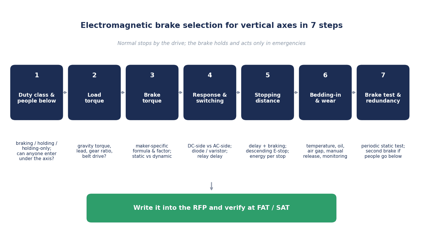
| Step | What to decide | Main checkpoints |
|---|---|---|
| ① Duty class | Normal stops are controlled stops; the brake is for holding plus emergencies. Which of braking / holding / holding-only? Do people enter the area under the axis? | Expected number of emergency braking operations. If people enter under the axis, assume redundancy |
| ② Load torque | Gravity torque of the vertical axis, screw lead, reduction ratio, whether there is a belt | How efficiency was treated (1.0, or divided by the efficiency) |
| ③ Required brake torque | Formula and factor of the adopted maker | Compare with static friction torque or with dynamic friction torque? |
| ④ Response time and switching circuit | Armature release time, DC-side / AC-side switching, diode / varistor, relay | Do the measurement conditions of the catalog value match the actual circuit? |
| ⑤ Stopping distance and emergency braking work | Fall during the delay + deceleration distance during braking. An emergency stop while descending is the worst case | Braking work per operation [J], count, frequency |
| ⑥ Bedding-in, temperature, wear, monitoring | Initial torque, temperature derating, oil and rust, gap adjustment, manual release, release monitoring | How to confirm “the torque you actually have now” |
| ⑦ Testing, redundancy, ordering | Periodic brake test, redundancy, RFP, FAT/SAT, spare parts | Test torque, frequency and records; configuration when people enter under the axis |
These 7 stages are not one-way. For example, if step ⑤ shows the stopping distance is too long, go back to the switching circuit in step ④; if that is still not enough, consider a brake with more torque in step ③; and if step ⑦ shows that people will enter under the axis, revisit the configuration itself in step ①. The flow of ordering and acceptance including motors and drives is covered in “Servo Control Procurement and FAT/SAT Guide for Thailand Plants in 2026“.
Brake Torque Calculation: Load Torque and Safety Factors on a Vertical Axis
Gravity torque of a vertical ball screw
The torque with which a load on a vertically mounted ball screw tries to descend is given in Ogura Clutch’s 2020 catalog by the following formula.
T = 9.8 × m × P / 2π [N·m] (m: mass of the linearly moving object, kg; P: screw lead, m/rev; efficiency taken as 1.0)
Miki Pulley’s technical documentation, on the other hand, uses a form that includes the efficiency η and friction: Tℓ = R × P/(2π) × (F + μMg)/η (R is the reduction ratio, F the external force). When applying this form to holding against gravity on a vertical axis, F would be treated as the gravity force Mg, but this is this article’s own application. Ogura’s formula uses an efficiency of 1.0, while Miki’s form divides by the efficiency, so for the same axis Miki’s form gives a somewhat larger value. Require the calculation sheet to state which treatment was used to derive the load torque.
Each maker’s safety factor comes as a set: “what it is applied to” and “what it is compared with”
| Maker / body | Formula | Example factors (as defined by each maker) | Compared with |
|---|---|---|---|
| Ogura Clutch (2020 catalog) | Holding: Tsr > TMAX × f / Braking: Tdr > Td × f | f is 1.5 to 3.5 in the table; 2.4 in the vertical ball screw selection example | Holding: static friction torque Tsr; braking: dynamic friction torque Tdr |
| Miki Pulley (technical documentation) | Holding: T = Tℓmax × K, Ts > T | K: low inertia, small load fluctuation 1.5; normal inertia, general use 2; large inertia, large load fluctuation 3 | Static friction torque Ts |
| mayr (recommendations for the static brake test) | MTest > ML × s, MMin > MTest × 1.25 | s is 1 to 1.3 (according to DGUV or standards) | Test torque, and the brake’s minimum braking torque MMin |
| DGUV (example measure in FBHM-005) | Test moment = load torque × 1.3 | 1.3 | Torque applied in the periodic brake test |
| Kendrion (Servo Line) | — | — | Shows “minimum guaranteed static torque over lifetime” and “static nominal torque” separately |
Ogura Clutch states that for braking, dynamic friction torque rather than static friction torque must be considered, explaining that the dynamic friction torque of dry friction types decreases as the slip speed increases. In other words, the holding check and the emergency braking check are compared against different things. Also, mayr’s MMin is the “minimum braking torque taking tolerance and temperature-related reduction into account,” not the catalog nominal torque itself. This is why the safety factor cannot be stated as a single number such as “generally X times.”
Model calculation A: on the same axis, the required torque changes with whose formula is used and what it is compared with
Here we apply each maker’s approach to the same inputs. The inputs are borrowed from the vertical ball screw selection example in Ogura Clutch’s 2020 catalog. This is not a design value for any specific machine; it is an example to show the structure and sensitivity of the calculation.
- Load mass m: 400 kg
- Screw lead P: 0.02 m
- Reduction ratio: 1/5 (the brake and motor side is faster)
- Efficiency: 1.0 (as treated in Ogura’s example), g = 9.8 m/s²
The gravity torque on the screw shaft is T = 9.8 × 400 × 0.02 ÷ 2π ≈ 12.5 N·m (the same 12.5 N·m as in Ogura’s example). Converted to the brake shaft, × 1/5 gives about 2.50 N·m (2.496 N·m).
| Approach (maker / body) | Formula | Value (brake shaft) | Compared with |
|---|---|---|---|
| DGUV test torque (example measure) | 2.50 × 1.3 | About 3.2 N·m | Torque applied in the periodic static test |
| mayr minimum torque for testing | 2.50 × 1.3 × 1.25 | About 4.1 N·m | The brake’s minimum torque (MMin > 1.25 × MTest, taking s = 1.3 for MTest) |
| Miki Pulley (divided by efficiency 0.85, K = 2) | 2.50 ÷ 0.85 × 2 | About 5.9 N·m | Static friction torque Ts |
| Ogura Clutch (efficiency 1.0, f = 2.4) | 2.50 × 2.4 | About 6.0 N·m (6 N·m in Ogura’s example) | Static friction torque Tsr |
| Miki Pulley (efficiency 0.85, K = 3) | 2.50 ÷ 0.85 × 3 | About 8.8 N·m | Static friction torque Ts |
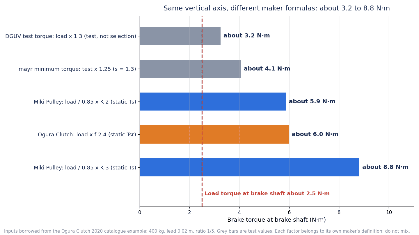
Even for the same axis, the result ranges from about 3.2 to 8.8 N·m, a spread of about 2.7 times. Note, however, that the top two rows are “test” figures, not “selection” figures, and are different in nature. DGUV’s about 3.2 N·m is the torque applied to the axis in the periodic test, and mayr’s about 4.1 N·m is the minimum torque the brake should have in order to withstand that test. The bottom three rows are figures for the torque required for holding, to be compared with static friction torque.
What matters here is not which one is correct, but that each factor is meant to be used together with that maker’s own definitions. A figure obtained with one maker’s factor should not be compared with another maker’s catalog value. As preconditions for any comparison, keep in mind that Miki Pulley’s form divides by the efficiency and so gives larger values, and that Ogura’s example is calculated with an efficiency of 1.0.
In Ogura Clutch’s selection example, the holding-type RNB-N0.8 with a rating of 8 N·m is selected against a required torque of 6 N·m. If, on the other hand, Miki Pulley’s approach (divide by efficiency 0.85, K = 3) is applied to the same axis, the required static friction torque is about 8.8 N·m, and selecting from Miki Pulley’s products would require a model with a static friction torque above 8.8 N·m. Whether a model of around 8 N·m is enough or the next size up is needed depends on whose approach is adopted. In other words, the choice of factor alone can change the selected model by one size. The f values in Ogura Clutch’s table (1.5 / 1.7 / 2.0 / 2.4 / 3.5) are chosen according to the degree of load fluctuation, inertia and shock; the 1.5 column lists examples such as blowers, fans and small machine tools, and the 3.5 column lists examples such as heavy rolling mills and large presses. Require the calculation sheet to state not only the value of the factor but also “which maker’s table it came from, and under which condition it was chosen.”
Note also that Miki Pulley’s selection cases include an example of choosing a holding brake for a ball screw drive (BXH-06), but its load torque is calculated from the screw friction μMg, and it is not a calculation example for holding against gravity on a vertical axis. When reusing a case, confirm which force is being held.
The required torque changes greatly during descent
In Miki Pulley’s selection case for a braking brake (lifting operation with a drum hoist, BXL-12), the required torque for the same load is about 0.57 N·m when ascending, versus about 15.3 N·m when descending. This is because while ascending the load assists the brake, and while descending the load works against the brake. In Ogura Clutch’s formula as well, the dynamic friction torque needed for deceleration is Td = J·n/(9.55·tab) ± T, with minus when the load assists the brake and plus when it hinders it. For emergency braking on a vertical axis, descent is the worst case.
Brake Response Time and Switching Circuits
Total braking time is the sum of three times
Ogura Clutch defines the total braking time as “actual braking time + armature release time + initial delay time.” The initial delay time is the time from the operating input (for example, an emergency stop signal) until the actuating input reaches the brake itself, and this includes the processing time of relays and controls. Miki Pulley likewise defines “total braking time ttb = tid + tar + tab,” and in its selection case sets the initial delay tid to 0.05 s based on the operating time of a typical relay. In other words, the catalog armature release time alone does not tell you the time until braking actually starts.
DC-side and AC-side switching change the armature release time severalfold
There are two places to cut the brake’s power: on the DC side after rectification, or on the AC side before the rectifier. Miki Pulley describes AC-side switching as “a general switching method that is easy to connect,” and DC-side switching as having “even faster operating characteristics than AC-side switching.” The following table extracts the differences for the same brake from each maker’s original tables.
| Maker / series / size | DC-side switching | AC-side switching | Ratio |
|---|---|---|---|
| Miki Pulley BXH-06 (holding) armature release time tar | 0.020 s | 0.070 s | 3.5x |
| Miki Pulley BXH-16 (holding) armature release time tar | 0.030 s | 0.140 s | About 4.7x |
| Miki Pulley BXL-12 (braking) time to 80% of rated torque tp | 0.055 s | 0.275 s | 5x |
| mayr ROBA-servostop Classic size 50 connection time t1 | 55 ms | 340 ms | About 6.2x |
| mayr ROBA-servostop Classic size 100 connection time t1 | 70 ms | 440 ms | About 6.3x |
| mayr ROBA-servostop Classic size 160 connection time t1 | 90 ms | 590 ms | About 6.6x |
| mayr ROBA-servostop Lean size 100 connection time t1 | 30 ms | 150 ms | 5x |
The notes on each of Miki Pulley’s specification tables say “armature attraction time and release time are values for DC-side switching,” and the AC-side values are listed in the table for the 45 V and 90 V specifications (single-phase half-wave rectification). In other words, the armature release time shown in a catalog’s list table will not necessarily be the value on the actual machine.
Surge absorbers also change it
Even without cutting on the DC side, the time changes with the type of surge absorber connected in parallel with the coil.
- In a note for the HK-KT, Mitsubishi Electric states that the brake control relay should be chosen considering the characteristics of the brake and the surge absorber, and that using a diode as the surge absorber makes the braking time longer.
- For Panasonic’s MINAS A4 (discontinued) MHMA152S1D, the armature release time is given as “50 (130) ms or less,” with a note that 50 ms applies when a brake surge absorber (SEMITEC Z15D151 or equivalent) is used, and the 130 ms in parentheses is a measured value when a diode is used (about 2.6 times).
- In the ROBA-servostop Lean installation and operational instructions, mayr explains that switching off with a freewheeling diode lets the magnetic field decay slowly, making the connection time t1 about 6 to 10 times longer than with DC-side switching, and that this suits applications where the connection time does not matter.
- The coupling time tc1 of the Kendrion Servo Line (12 ms for size 06) is noted as measured with fast switching using a parallel varistor.
- In a note for the Σ-7 SGM7J, Yaskawa states that the time required for release and the time required for braking change depending on which discharge circuit is used, and asks users to check that the operation delay time is appropriate for the actual machine.
DC-side switching has cautions too
So should you always switch on the DC side? That cannot be said outright either. mayr writes that DC-side switching produces high voltage peaks in the coil that can lead to spark wear of contacts and insulation breakdown, so the voltage peaks should be limited (with the varistor selected for the maximum DC and AC voltage). Miki Pulley also asks that, when switching on the DC side with a power supply that has no built-in protective element, the recommended protective element (varistor) be connected in parallel with the brake. For Ogura Clutch’s ORM0509F/H power supply, the connection diagrams show “AC-side switching (recommended)” alongside “DC-side switching,” and state that when switching on the DC side, a back-surge absorbing element must always be connected across the load terminals, and that when contact life is short, it can be extended by connecting two or more contacts in series. This “recommended” is stated from the standpoint of protecting the power supply and ease of use, not as a comparison of response times.
In other words, the switching method, protective elements and relays are items that should carry the same weight in the specification as the brake model itself. Confirm which circuit the catalog armature release time was measured with, and measure it with the actual circuit at FAT. Mitsubishi Electric also states that the release delay should be confirmed on the actual machine.
An overexcitation power supply is for “faster release”
A similar-sounding term is the overexcitation power supply. Ogura Clutch’s OCP25 is a power supply that speeds up armature attraction by overexcitation so the brake releases quickly, then reduces temperature rise and power consumption with reduced excitation. This is a measure to speed up the release side (attraction time), and it works in a different direction from a means of shortening the armature release time from power-off until braking starts.
Examples of armature release time for built-in brakes
| Maker / type | Time from power-off to braking start (each maker’s term) | Conditions / notes |
|---|---|---|
| Mitsubishi Electric HK-KT053WB to 13WB | Braking delay 0.01 s | Value for DC off (DC-side switching) |
| Mitsubishi Electric HK-KT23WB to 63(4)WB | 0.02 s | Same as above |
| Mitsubishi Electric HK-KT153(4)WB to 202(4)WB | 0.03 s | Same as above |
| Panasonic MSMF402L1D6 (MINAS A6) | Armature release time 50 ms or less | Values differ by part number (MSMF092A1D2 is 20 ms or less) |
| Yaskawa SGM7J (50 to 750 W) | Time required for braking 100 ms | Changes with the discharge circuit |
| Ogura Clutch RNB-N0.8 (holding) | Armature release time 15 ms | 2020 catalog. Coil at 20 °C. A note on the switching condition could not be confirmed in this article |
These values differ between makers, including how the measurement conditions are written. They are placed in the same table to give a “sense of the order of magnitude,” not to rank brakes against each other.
Vertical Axis Fall Prevention: Calculating the Stopping Distance
Think of stopping distance in two stages: “during the delay” and “during braking”
Miki Pulley gives the stopping angle, for cases where stopping accuracy needs to be confirmed, as θ = 6 × n × (tid + tar + ½·tab) [°], and the scatter of the stopping position empirically as Δθ = ±0.15 × θ. This formula assumes that during the delay (tid + tar) the shaft keeps rotating at speed n.
On a vertical axis, one more effect is added. mayr writes that load torque reduces the available deceleration torque and can increase the output speed during the control’s processing time and during the brake’s delay time. In other words, the stopping distance of a vertical axis must be considered in two stages: “the distance travelled while accelerating under gravity during the delay” and “the distance needed to decelerate from that speed with the net torque after subtracting the load torque.”
Model calculation B: a long braking delay greatly extends the stopping distance in an emergency stop during descent
Using the same axis as in model calculation A (the values of the selection example in Ogura Clutch’s 2020 catalog), we calculate the stopping distance when the assumed braking delay is changed.
The inertia referred to the brake shaft is screw 6.24×10⁻⁴ × (1/5)² + motor 10×10⁻⁴ + brake 0.782×10⁻⁴ + converted load mass about 1.62×10⁻⁴ ≈ 12.7×10⁻⁴ kg·m², which matches the total inertia of 12.7×10⁻⁴ kg·m² in Ogura’s example. For the dynamic friction torque during braking, we use 5.6 N·m, the value assumed in Ogura’s example.
Assumptions (please keep these in mind when reading this calculation)
- During the delay, the motor torque is zero and the brake is not yet acting
- Efficiency of 1 and no friction; braking torque is constant
- This is a rough approximation that ignores the speed limit of the brake shaft and motor overspeed; it is not a prediction of the stopping distance of an actual machine
- The delay values are a sensitivity calculation that borrows the armature release times of brakes of different makers and sizes as “assumed delay values”, not a comparison ranking brakes against each other. The 0.05 s for relays and similar is the value assumed in Miki Pulley’s case
Under these conditions, the acceleration during the delay is about 1.26 m/s², about 1/8 of the gravitational acceleration of 9.8 m/s². This is because, in this calculation, the inertia of the rotating parts (screw, motor and brake) greatly slows the fall. The deceleration during braking is about 1.56 m/s². A descent speed of 0.12 m/s corresponds to 1,800 r/min at the brake shaft (the speed in Ogura’s example).
| Assumed braking delay (power-off to braking start) | From standstill (holding in a power failure) | Emergency stop while descending at 0.12 m/s |
|---|---|---|
| 0.065 s (relays etc. 0.05 s + Ogura RNB-N0.8 armature release 0.015 s) | About 4.8 mm | About 23.5 mm |
| 0.12 s (relays etc. 0.05 s + Miki BXH-06 AC-side switching 0.070 s) | About 16.3 mm | About 46.9 mm |
| 0.19 s (relays etc. 0.05 s + Miki BXH-16 AC-side switching 0.140 s) | About 40.9 mm | About 86.6 mm |
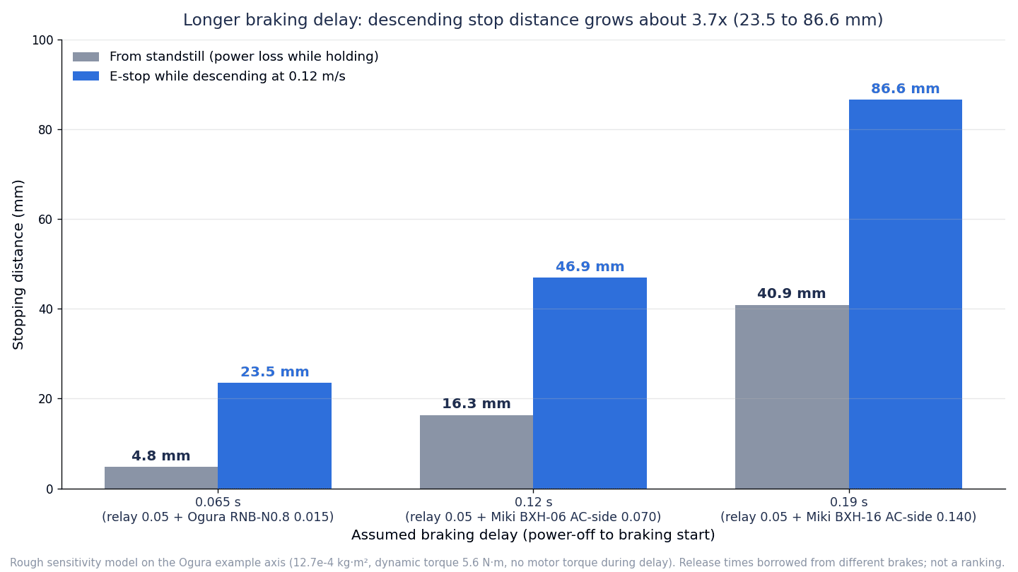
Looking at the breakdown, the about 23.5 mm for 0.065 s while descending is “about 10.5 mm during the delay + about 13.0 mm during braking,” and the about 86.6 mm for 0.19 s while descending is “about 45.5 mm during the delay + about 41.2 mm during braking” (each value is rounded, so the sum of the breakdown may differ from the total by 0.1 mm). When the delay goes from 0.065 s to 0.19 s, the stopping distance during descent goes from about 23.5 mm to about 86.6 mm, about 3.7 times. The delay itself is about 2.9 times longer, but the stopping distance grows by more than that. Because the speed rises during the delay and the axis must then be stopped from that higher speed, the effect of the delay is not linear.
For reference, free fall for the same time (½gt²) gives about 20.7 mm for 0.065 s and about 177 mm for 0.19 s. The calculated values from standstill (about 4.8 mm and about 40.9 mm) are much smaller than free fall because the inertia of the rotating parts restrains the acceleration. Put the other way, on an axis with small inertia, or if a belt breaks and only the screw-side inertia remains, the axis may fall faster than this calculation suggests.
Start by reviewing the switching circuit specification
The row set at 0.12 s in the calculation borrows the armature release time of 0.070 s for Miki Pulley’s BXH-06 with AC-side switching. If the same BXH-06 is switched on the DC side, the armature release time is 0.020 s, about 1/3.5 of the AC-side value. Before enlarging the brake or changing the motor, specifying the switching circuit is one of the first measures worth considering to shorten the stopping distance. As the previous section showed, however, DC-side switching comes as a set with surge protection (varistor) and attention to contact life.
Emergency braking work and count
Alongside the stopping distance, the work (energy) the friction surfaces absorb in one emergency braking operation should be checked.
- In Ogura Clutch’s selection example, the braking work of the RNB-N0.8 in an emergency stop is calculated as about 41 J from a dynamic friction torque of 5.6 N·m and a total inertia of 12.7×10⁻⁴ kg·m². The example also gives, as a guideline for the permissible work of a holding brake up to an emergency stop, “up to 70% of the permissible work rate of a braking brake of the same torque size.”
- Miki Pulley states that for holding purposes, braking is limited to emergencies, with the condition that the braking work per emergency braking operation, Eb, is sufficiently smaller than the permissible braking work Ebaℓ (Eb ≪ Ebaℓ). It sets the frequency of emergency braking at no more than about once per minute, and writes that if Eb per operation is 70% or more of Ebaℓ, the brake should be cooled sufficiently after emergency braking before use. The total number of braking operations is estimated as L = ET/Eb.
- The permissible braking work of Mitsubishi Electric’s HK-KT is 5.6 J, 22 J, 64 J or 66 J per operation (depending on the type), and values per hour are also given. The maximum switching energy per emergency stop of Kendrion Servo Line size 06 is 70 J.
In an emergency stop during descent, the braking work also grows because the speed rises during the delay. For example, with a product whose limit on emergency stops is 500, repeating emergency stops many times during commissioning and adjustment risks approaching that limit. In the RFP, require “the expected number of emergency braking operations” and “the work per operation [J]” to be stated as a pair with the brake’s permissible values.
Catalog Torque Is Not Necessarily “the Torque You Have Now”
Bedding-in (initial torque)
Friction brakes may not deliver their stated torque when first used, because the friction surfaces have not yet bedded in.
- In its technical documentation for electrically applied brakes, Miki Pulley explains that the initial torque is 60 to 70% of the stated torque and reaches the stated value after a short run-in, and that run-in may take longer at light loads or low speeds. Its documentation for power-off actuated brakes also says that the torque may be below the stated value in early use, and that the friction surfaces should be bedded in by a run-in before use (no specific ratio of initial torque is given for power-off actuated brakes).
- Ogura Clutch adds the note “(initial torque is 70% of rated torque)” in the series introductions for SNB-N, MNB-N, PNB and others.
- In a table note for the ROBA-servostop, mayr states that the nominal braking torque listed is a lower limit with a very high probability of being reached but cannot be guaranteed, and that the braking torque can deviate due to the run-in condition, temperature, wear, contamination and so on, so the variation should be allowed for with suitable safety measures at the design stage. The Lean installation and operational instructions state that after long storage or standstill, run-in may be needed to obtain the specified torque.
- Kendrion Servo Line shows a minimum guaranteed torque over the lifetime for brakes that have been factory grinded-in and torque tested.
On machines just after commissioning, or machines being started after a long standstill, the catalog torque is not necessarily available as stated. Include the run-in procedure at commissioning and the subsequent torque check in the specification.
Temperature, oil and rust
- Temperature: mayr’s ROBA-servostop is for 0 to 60 °C, and shows braking torque reductions of 10% above 60 °C up to 80 °C, 20% above 80 °C up to 100 °C, and 30% above 100 °C up to 120 °C. Brakes built into motors receive heat from the motor, so the temperature inside the machine needs to be estimated. Note also that mayr’s braking torque tolerance is given as “+75%,” and only the upper side is stated.
- Oil and wear: The DGUV information sheet states that during production, a stopped vertical axis is usually held only by the brake built into the motor, and that mechanical wear or oil contamination can make the brake’s braking torque fall below the nominal value, leading to unintended descent or the axis falling.
- Rust: mayr cautions that in corrosive environments or after long standstill, the rotor can rust and seize.
Gap adjustment and life
As the friction surfaces wear, the air gap between the armature and the field widens. How the gap is handled differs greatly by product.
| Maker / series | Gap adjustment | Approach to life and inspection |
|---|---|---|
| Ogura Clutch SNB-N (braking) | Inspect periodically and adjust to the specified gap. Measure at 3 points around the circumference; each measurement within 0.05 mm of the others | Shows the maximum gap and total work until readjustment (example: size 10 has a maximum gap of 0.80 mm, total work of 1.6×10⁸ J, specified gap 0.2 to 0.35 mm). Beyond the limit gap, the brake can no longer be released |
| Miki Pulley BXW, BXR, BXL, BXH, 457 | No adjustment needed (adjusted before shipment) | Estimate the total number of braking operations as L = ET/Eb |
| Mitsubishi Electric HK-KT | Cannot be adjusted | Life is “the number of braking operations until gap adjustment would be needed” |
| mayr ROBA-servostop | No adjustment of the operating air gap needed (vendor claim) | For the Lean, wear is judged by measuring the release voltage (in the warm state, up to a maximum of 90% of the overexcitation voltage). Inspection intervals are calculated individually in the system manufacturer’s plan |
Ogura Clutch also writes that the time it takes for the brake to be released (opened) changes with the size of the air gap. In other words, as wear progresses, the release-side operation changes too. The life formulas are L = V/(Eb·w) or L = Et/Eb for Ogura Clutch, and L = ET/Eb for Miki Pulley; in every case, the calculation is only possible once “the braking work per operation” is known. Here again, estimating the emergency braking work is the foundation.
On cleaning, mayr asks that brake dust not be blown away with compressed air or brushes but removed by suction or with a damp cloth, and recommends an FFP2 mask if dust is produced.
Manual release is an “operation that lets the load fall”
Some brakes have a manual release mechanism so the axis can be moved during a power failure or fault.
- Ogura Clutch SNB-N sizes 1.2 to 10 and RNB-N sizes 3 to 20: screw type, released by tightening the screws alternately until they have turned about 90 degrees (do not force them further)
- Miki Pulley BXL and BXH: manual release possible (for BXL and others, a manual release lever is available as an option in addition to the standard manual release tapped holes)
- mayr ROBA-topstop: option for manual release in situations without power
- INTORQ BFK458: variations in the manual release position, and microswitch monitoring of the manual release, available as options
- Mitsubishi Electric HK-KT: no manual release mechanism (released electrically with 24 V DC)
If a vertical axis is manually released, the load falls. Together with deciding whether manual release is needed, how the load will be supported before release (support fixtures, moving to the lowest position, mechanical locking) must be fixed as a procedure. For maintenance, DGUV also lists supporting the axis if it can be supported or lowering it to the lowest position, and, if it cannot be supported, using a safe position-fixing device (arresting device) whose state is checked and interlocked on the control side.
Release monitoring
How to confirm whether the brake has actually opened (or closed) also differs by product. The INTORQ BFK458 offers, as options for size 12 and above, microswitches for switching function monitoring and wear monitoring. mayr explains that its ROBA-brake-checker detects armature movement without sensors by analyzing current and voltage, and monitors the open/closed state, coil temperature, wear and functional reserve (vendor claim). DGUV states that motor brakes generally do not have a reliable signal output for open/closed. Whether release monitoring is needed is decided together with the testing and redundancy configuration in the next section.
Brake Testing and Redundancy
Status of the DGUV information sheet
The DGUV FBHM-005 “Gravity-loaded axes – Vertical axes” (English translation, dated August 17, 2021) referred to here is an information sheet from the German Social Accident Insurance. Please read it as examples of measures presented by a German institution, not as requirements of international standards or of Thai law. DGUV itself states that no specific standard exists for assessing the risks of vertical axes, and lists DIN EN ISO 12100 and its Annex B (which includes hazards due to gravity) as the general principles for risk assessment. Note also that the ISO 13849-1 referred to by DGUV is the 2016 DIN EN version, not the current ISO 13849-1:2023.
The configuration changes depending on whether people enter under the axis
In the DGUV tables, the level of measures is divided according to how people are exposed to the hazard.
- Where the design prevents people from entering under the axis and only the upper limbs are exposed to the hazard for a short time: periodic testing of the brake device by the machine control (category 2 of DIN EN ISO 13849-1)
- Where entering under the axis cannot be avoided: a redundant fall-prevention device (category 3, PLc)
DGUV’s Table 3 also shows which brake configurations match which operating modes. The symbols are DGUV’s classifications: A1 is when the operator is in a safe position or in an area protected against access, A2 is when the design prevents people from entering under the axis and only the upper limbs are exposed to the hazard for a short time, A3 is when entering under the axis cannot be avoided, and W1 and W2 are maintenance. Table 3 also has a separate series of operating modes starting with E, but this article has not confirmed their definitions, so the table below is limited to the A series and maintenance (W1, W2).
| Configuration (DGUV Table 3 classification) | Applicable operating modes (as organized by DGUV) |
|---|---|
| V0 Holding brake only | A1 only (operator in a safe position or in an area protected against access) |
| V1 Holding brake with periodic test | A1 and A2 (not A3, where entering under the axis cannot be avoided) |
| V2 Holding brake with safety-related control and drive | In A3 (where entering under the axis cannot be avoided), only if there is additional protection in a power failure |
| V3 Holding brake + second brake / V5 Holding brake + mechanical counterweight | A1 to A3 (including A3, where entering under the axis cannot be avoided) |
| V4 Safety brake, V8 Holding brake + hydraulic counterweight with brake valve, V9 Holding brake + safety clamping device | All modes, including maintenance (W1, W2) |
| V6 Support or mechanical lock | Maintenance (W1, W2) only |
What this shows is that unless “whether people enter under the axis” is decided first, the brake configuration cannot be decided. That is why it is decided in step ① of the 7 steps.
DGUV also states that a brake for holding a vertical axis can be classified as a safety component under Machinery Directive 2006/42/EC only if it is placed on the market separately from the machine or drive motor. A motor brake built into a drive motor is not placed on the market separately, so this provision does not apply. In other words, a motor’s built-in brake cannot by itself be regarded as a “safety component.”
Product examples of external brakes and redundancy
As a product example of a configuration corresponding to DGUV’s “holding brake + second brake,” there is mayr’s ROBA-topstop. mayr describes it as a smart safety brake for vertical axes, plug and play for standard servo motors, an easy solution for system redundancy, holding the load even when the motor is removed, and retrofittable to existing structures because it sits between the motor and the output (vendor claim). mayr also states that it can be regarded as a tried and tested (well-tried) component in the sense of category 1 of DIN EN ISO 13849-1, and its press release of October 21, 2025 states that TÜV judged it a category 1 well-tried component. However, what mayr writes is an assessment as a category 1 component; it does not go so far as to say that using this product makes the safety function of the whole machine meet a particular category or performance level. The level of a safety function is assessed for the whole, including the circuit, diagnostics and component reliability. How to verify safety-related parts is covered in “Safety PLC Implementation: RFP, Validation and FAT/SAT Evidence“.
As mentioned in an earlier section, on an axis where the screw and the motor are connected by a timing belt, the motor’s built-in brake alone cannot hold the axis if the belt fails. Consider a configuration with an external brake on the screw side, or combined with a mechanical stopper or lock.
How to perform the periodic static brake test
DGUV’s Table 2 gives the following examples of measures for the category 2 periodic brake test.
- Perform it in a safe position
- Perform it automatically during normal operation, at intervals of no more than 8 hours or one shift (for equipment where access is reliably prevented by doors with guard locking, it may also be done just before an unlocking request)
- At least the maximum static load must be held reliably. The test moment is 1.3 times the load torque
- When two brakes are used in parallel, testing them one at a time in sequence with a simple load is sufficient
- Apply the test moment for a sufficient time
- After a faulty brake has been repaired, the test is forced by the control and operation is not allowed until it passes
- At commissioning, perform and record an acceptance test that simulates a brake failure and confirms the response to the failure (the form is prepared by the machine manufacturer)
As general requirements, DGUV also lists designing the mechanical parts of the power transmission and the safety devices to withstand the static and dynamic stresses arising from at least twice the weight load, and moving to a safe position immediately if possible when a brake failure is detected. All of these are example measures of a German institution and do not automatically become obligations at a plant in Thailand, but they provide a concrete starting point for designing the test.
mayr’s “Remarks and recommendations for the static brake test (rotation brakes)” lists the following points from a manufacturer’s standpoint.
- Perform brake tests only in a safe axis position
- The size of the test torque and the test frequency are determined by the machine manufacturer. Take the test torque into account when selecting the brake
- As an example, the test duration is a hold of 1 to 5 seconds (with the full torque applied). Increase the torque smoothly, not abruptly
- When testing from the control side, the permissible rotation angle should be at least the sum of the angle due to system deflection, the backlash of gears and brake, and the 5° of rotor rotation needed for the friction value of the braking torque to build up
- If the test fails, inspect for incorrect application and the condition of the brake, condition the friction pair by dynamic braking if necessary, and retest
As a drive-side function, SEW-EURODRIVE explains “SBT (Safe Brake Test)” in its MOVIPRO documentation as a static brake test for horizontal and vertical applications, which diagnoses whether the brake can hold a static test torque applied against the closed brake. It states that at commissioning, the setting is made so that the sum of the application’s load torque and the motor torque equals the required test torque. Note, however, that the list of “safety subfunctions according to EN 61800-5-2” in the same documentation includes SBC (Safe Brake Control), which handles brake control, but does not include SBT. SBT is best understood as a name that individual companies use for a drive function.
Passing a static test does not guarantee emergency stop performance
This is one of the points this article most wants to stress. DGUV states explicitly that, where the brake also performs an emergency stop function, an automatic static brake test does not sufficiently prove that the emergency stop performance is neither insufficient nor degraded. Its explanation is that static and dynamic conditions have different physical characteristics, so even if the static test is passed, the overrun at an emergency stop can be slightly longer. On that basis, it states that stop category 1 (controlled stop) should be given priority for protective stops so that the emergency stop function is not assigned to the brake.
In other words, even if the periodic test confirms that the brake “can hold,” “how many mm the axis takes to stop at an emergency stop during descent” must be confirmed separately. As model calculation B showed, the stopping distance changes greatly with the length of the delay. At FAT/SAT, check the static holding torque and measure the dynamic stopping distance separately, and record each.
Common Failures and Their Causes
Based on what is written in the maker documents and the DGUV information sheet, the main causes are organized by symptom.
| Symptom | Main causes (within the sources) | Checks and countermeasures |
|---|---|---|
| The axis drops a little in a power failure | It accelerates under gravity during the armature release time and the delay of relays etc. (the total braking time concept of Miki Pulley and Ogura Clutch, mayr’s explanation of load torque). AC-side switching or diodes extend the delay | Check the switching method and protective elements; measure the drop from standstill |
| It goes down too far in an emergency stop | During descent, acceleration during the delay combines with a reduced net deceleration torque due to the load torque (mayr). This cannot be seen from the pass/fail of a static test (DGUV) | Calculate and measure the stopping distance during descent; prioritize controlled stops |
| The brake drags or heats up | When wear makes the air gap exceed the limit, the brake can no longer be released (Ogura Clutch SNB-N). A holding brake is being used for normal braking (prohibited by each maker) | Inspect and adjust the air gap (on products that allow adjustment); review how it is used |
| The torque is not reached | Initial torque before bedding-in (Miki Pulley, Ogura Clutch), temperature derating (mayr), oil contamination and wear (DGUV), rust after long standstill (mayr) | Run-in, check temperature, static brake test |
| Abnormal noise as the servo moves during the release delay | There is a release delay, but the time from release to motor start is too short (Mitsubishi Electric) | Confirm the release delay on the actual machine and adjust the start timing |
| A belt-driven axis cannot be held | In structures where the motor and the screw are connected by a timing belt, the motor brake may not be able to hold the axis (Mitsubishi Electric) | Brake on the screw side, stopper on the machine side |
| The brake test fails | Incorrect application, the brake’s condition, the condition of the friction pair (mayr) | Inspect; if necessary, condition by dynamic braking and retest. After repair, do not allow operation until it passes (DGUV) |
Many of the items in the table arise because the selection and wiring assumptions are not visible to the buyer. The RFP items in the next section are there to have those assumptions written down from the start.
12 Items to Include in an Electromagnetic Brake RFP (Request for Quotation)
These are the items worth including in the specification for a vertical axis with a brake when requesting a quotation from a machine builder or SIer. They are assembled from the makers’ technical documents and the DGUV information sheet. Not everything needs to be fixed as a number; the purpose is to have the supplier write down “what assumptions the selection was based on.”
| No. | Item | What to have written | Reason |
|---|---|---|---|
| 1 | Axis configuration and load torque | Mass, lead, reduction ratio, whether there is a belt, calculation of the maximum load torque (source of the formula and treatment of efficiency) | The value changes depending on whether efficiency is 1.0 or divided out |
| 2 | Safety factor and comparison target | Maker name and table name of the factor used; whether it was compared with static or dynamic friction | What it is applied to and compared with differs by maker |
| 3 | Brake class and normal stopping method | Braking / holding / holding-only; whether normal and protective stops are done by controlled stop | Holding brakes cannot be used for normal braking |
| 4 | Expected emergency braking | Expected count, braking work per operation [J], frequency, comparison with permissible values | Count limits differ widely by product |
| 5 | Armature release time and its conditions | Switching method (DC side / AC side), model of protective element, relay | The armature release time changes severalfold with the circuit |
| 6 | Stopping distance | Calculated values from standstill and during descent, calculation assumptions, permissible values | An emergency stop during descent is the worst case |
| 7 | Temperature and environment | Estimate of the temperature inside the machine; countermeasures against oil, dust and corrosion | Torque drops with temperature; oil and rust bring it below the nominal value |
| 8 | Gap and inspection method | Whether adjustment is needed; wear inspection method and interval | Some products can be adjusted and some cannot |
| 9 | Manual release | Whether needed, and the support procedure when releasing on a vertical axis | Manual release is an operation that lets the load fall |
| 10 | Release monitoring | Whether microswitches or sensorless monitoring are needed | Motor brakes generally have no open/closed signal (DGUV) |
| 11 | Periodic brake test | Frequency, test torque, hold time, permissible rotation angle, pass/fail criteria, records | Take the test torque into account at selection (mayr) |
| 12 | Redundancy | Whether people enter under the axis; whether there is a second brake, stopper or lock | The configuration changes depending on whether people enter (DGUV) |
Items 2, 4 and 5 in particular make a difference at the quotation comparison stage. If company A writes “6 N·m or more with Ogura Clutch’s factor 2.4” and company B writes “8.8 N·m or more with Miki Pulley’s K = 3,” you can explain why the brake sizes look different even for the same axis. For ordering equipment whose main job is lifting, see “Vertical Reciprocating Conveyor Selection: VRC vs Continuous, RFP and FAT/SAT for Thai Plants“, and when using a rod-type actuator vertically, “Electric Cylinder Selection for Thai Factories” is also useful.
What to Check at FAT/SAT
These are the items worth checking for a vertical axis with a brake at the factory acceptance test (FAT) and the site acceptance test (SAT). The test torque and time values are shown as examples from individual makers and institutions.
| Test item | Method | Criterion | Record |
|---|---|---|---|
| Static holding torque after bedding-in | In a safe axis position, raise the test torque smoothly and hold it for the specified time (mayr’s example is 1 to 5 seconds) | Holds within the permissible rotation angle | Test torque, hold time, rotation angle |
| Fault simulation | Simulate a brake failure and confirm the control’s response (DGUV lists this as an acceptance test at commissioning) | Transition to a safe position, prohibition of operation, etc., as specified | Simulation method, response, person performing it |
| Stopping distance at emergency stop | Apply emergency stops while ascending, descending and at maximum speed, and measure | Within the calculated and permissible values | Speed, stopping distance, count |
| Drop in a power failure | Cut the power at standstill and measure the drop | Within the permissible value | Drop |
| Armature release time and attraction time | Measure with the actual wiring and switching circuit (Mitsubishi Electric asks that the release delay be confirmed on the actual machine) | As per the conditions in the specification | Switching method, protective element, measured values |
| Order of release and servo-on | Confirm the sequence does not move the motor during the release delay | No abnormal noise or dragging | Sequence settings |
| Manual release procedure | Confirm with the procedure using support fixtures | Can be released with the load supported | Procedure document, support fixtures |
| Periodic test settings | PLC and drive cycle, test torque, pass/fail criteria, behavior on failure | As specified | Settings, confirmation of behavior on failure |
| Managing the emergency braking count | Record the number of emergency braking operations during commissioning and adjustment | Know the remaining count against the permissible count | Cumulative count |
At SAT, the basic approach is to re-measure the static holding torque and stopping distance after transport and installation using the same method as at FAT. Also compare the wiring diagram with the actual installation to check that the switching circuit has not changed with the local power supply or relay panel. As DGUV states that the record form is “prepared by the machine manufacturer,” having the machine builder prepare it at the RFP stage makes acceptance smoother.
Handover to the maintenance plan
Hand over the periodic test results, the cumulative emergency braking count, the gap inspection results (for products that can be adjusted) and the temperature trends to the maintenance plan. For products such as Mitsubishi Electric’s HK-KT, whose life is determined by the number of braking operations, you cannot know when to replace them unless the emergency braking operations are counted. mayr states that the inspection and maintenance intervals for the ROBA-servostop Lean are calculated individually in the system manufacturer’s plan, so do not borrow intervals from other makers’ products; set them based on the installation and operational instructions of the product adopted.
Checkpoints for Procurement and Maintenance in Thailand
Contact points, within what official materials confirm
In the research for this article, the following two makers were the ones whose Thai contact points could be confirmed from official materials.
- Miki Pulley: its company history says Miki Pulley (Thailand) was established in Bangkok in July 2022, and the overseas sales network on its Business Locations page lists a distributor in Bangkok (NAM SAE INTERNATIONAL TRADING CO., LTD.).
- mayr: selecting Thailand as the country on its contact page shows the Regional Sales Manager of Mayr Transmission (S) Pte Ltd in Singapore as the contact (no address in Thailand is shown).
For other makers, this article has not confirmed Thai contact points through primary sources. A brake built into a servo motor is usually replaced together with the motor, so confirm the motor maker’s local contact point and the availability of the same type. For machines that use external European brakes, the reliable approach is to confirm with the machine builder at the RFP stage where replacement parts and inspection will be handled, and how long it takes to obtain them.
Spare parts and storage
If you keep spare brakes, pay attention to the storage period as well. mayr states that run-in may be needed after long storage or standstill, and that in corrosive environments the rotor can rust and seize. After replacing a brake with a spare, perform the run-in and the static holding torque check using the same method as at acceptance, and record the results. How to select the other parts of a vertical axis, such as linear guides and ball screws, is also covered in “Linear Guide Selection: Life Calculation, Preload, Accuracy and RFP for Thai Factories“.
BOI efficiency improvement measure (within the 2025 guide)
The Thailand Board of Investment (BOI) Investment Promotion Guide 2025 includes a measure for improving efficiency by introducing automation systems into existing production lines or services. The incentives are exemption of import duty on machinery and a 3-year corporate income tax exemption (capped at 50% of the improvement investment, excluding land cost and working capital); for automation and robotics, if 30% or more of the value of the improvement machinery is linked to or supports the automation industry in Thailand, the cap becomes 100%. Examples of excluded activities (general automobiles, some motorcycles, PHEVs and HEVs, cement, etc.) are also given. However, this measure covers investment in equipment and systems, and it does not say that purchasing a stand-alone part such as a brake is covered. Also, the description here is within the scope of the 2025 guide; please confirm the latest conditions and application status with the BOI. Please consult a specialist for tax decisions.
Frequently Asked Questions
Where should electromagnetic brake selection start?
Start with the duty class and whether people enter the area under the axis. On the premise that normal stops are controlled stops and the brake is used for holding and emergencies, decide which of braking, holding or holding-only to use. Then calculate the load torque, derive the required torque with the adopted maker’s formula and factor, and check in order: response time including the switching circuit, stopping distance and emergency braking work, bedding-in, temperature and wear, and testing and redundancy.
What is a power-off actuated brake?
It is a brake that acts when the power is cut and is released when energized. According to the explanation in Ogura Clutch’s 2020 catalog, when the current is cut, the spring force moves the armature away and friction torque is generated; when energized, the armature is attracted and the torque disappears. Because it acts even in a power failure, it is the basic form for vertical axis fall prevention. Besides the spring type there is also a permanent magnet type, and there are also duty classes: braking, holding and holding-only.
Can a servo motor holding brake be used for emergency stops?
It can be used only in emergencies, within the range the product allows. Mitsubishi Electric, Panasonic and Yaskawa all state that the built-in brake should not be used for normal braking (stopping a rotating motor). On the other hand, Mitsubishi Electric states that it is used for fall prevention in a power failure or servo alarm, and gives the permissible braking work and life count (20,000 operations for many HK-KT types, 5,000 for the larger types). The number of emergency stops for Kendrion Servo Line and INTORQ BFK458 (holding) is 500. Confirm the limits on count and on work per operation, and design so that normal stops and protective stops are made by controlled stopping.
What safety factor should be applied in a brake torque calculation?
There is no single answer. Ogura Clutch shows factors of 1.5 to 3.5 in a table and uses 2.4 in its vertical ball screw selection example. Miki Pulley uses K = 1.5, 2 or 3 for holding, depending on the load conditions. For testing, mayr gives a test torque of the load torque multiplied by 1 to 1.3, and a minimum braking torque of at least 1.25 times that. In this article’s calculation, the same axis gave a range of about 3.2 to 8.8 N·m. Calculate according to the adopted maker’s definitions, and require the calculation sheet to state whether the result was compared with static or dynamic friction.
How can the brake response time (armature release time) be shortened?
First check the switching circuit. The armature release time of Miki Pulley’s BXH-06 is 0.020 s with DC-side switching and 0.070 s with AC-side switching. Using a diode for surge absorption makes it slower; in the example of Panasonic’s MINAS A4 MHMA152S1D, 50 ms becomes 130 ms. With DC-side switching, suppress surges with a varistor or similar, and take contact life into account as well. The processing time of relays and controls also adds to the delay, so measure and confirm with the actual circuit.
How often should a brake test be performed?
The size of the test torque and the test frequency are determined by the machine manufacturer (mayr). As a reference example, the German DGUV information sheet lists a measure of testing automatically during normal operation, at least every 8 hours or once per shift, with a test moment of 1.3 times the load torque. This is an example measure of a German institution, not a requirement of international standards or of Thai law. Also, passing a static test does not guarantee the stopping distance at an emergency stop, so check the stopping distance separately.
Summary
- Electromagnetic brake selection does not end with “Is the catalog torque larger than the load?” Holding and braking are different jobs, and the emergency braking count of a servo’s built-in holding brake differs widely: 20,000 for many types of Mitsubishi Electric’s HK-KT versus 500 for Kendrion Servo Line and INTORQ BFK458 (holding). Normal stops are made by controlled stopping.
- What the safety factor is applied to and compared with differs by maker, and even for the same axis the result ranges from about 3.2 to 8.8 N·m, about 2.7 times. The choice of factor can change the model by one size, so require the calculation sheet to state “whose formula was used and what it was compared with.”
- The armature release time changes severalfold with the switching circuit (Miki Pulley BXH-06: 0.020 s DC side / 0.070 s AC side; mayr ROBA-servostop Classic size 100 connection time: 70 / 440 ms). In the calculation, when the delay went from 0.065 s to 0.19 s, the stopping distance during descent went from about 23.5 mm to about 86.6 mm, about 3.7 times.
- Catalog torque is not necessarily “the torque you have now.” It can drop due to bedding-in, temperature, oil, wear and rust, so a run-in at commissioning and periodic checks are needed.
- Passing a static brake test does not guarantee the stopping distance at an emergency stop. Whether people enter under the axis determines whether a holding brake with periodic testing or a redundant configuration is appropriate.
- In the RFP, require the class and expected emergency braking, the source of the factor, the switching method and protective elements, the stopping distance, the test method and redundancy to be stated, and measure and record the static holding torque and stopping distance at FAT/SAT.
TOMAS TECH supports the design of automated machines and inspection equipment, and the modification and upgrading of equipment, at Japanese-affiliated plants in Thailand. You can consult us even at the stage before the product or supplier has been decided, for example to isolate the cause when the Z axis of an existing machine drops or goes down too far in a power failure or emergency stop, or to draft RFP and FAT/SAT items for axes with brakes. Please contact us via this form.
References
- ISO: ISO 13849-1:2023 Safety of machinery — Safety-related parts of control systems — Part 1
- VDE VERLAG: IEC 61800-5-2:2016 preview (table of contents and foreword)
- DGUV: FBHM-005 Gravity-loaded axes – Vertical axes (English translation)
- DGUV: FBHM-005 Schwerkraftbelastete Achsen – Vertikalachsen (German original)
- Ogura Clutch: Power-off actuated brakes / clutches general catalog (2020 edition, Japanese)
- Miki Pulley: Power-off actuated brakes technical documentation (Japanese)
- Miki Pulley: Electromagnetic clutches and brakes catalog, electrically applied type technical documentation (Japanese)
- Miki Pulley: Permanent magnet brakes (Japanese)
- Miki Pulley: History
- Miki Pulley: Business Locations
- Mitsubishi Electric: Rotary Servo Motor User’s Manual (For MR-J5) (SH(NA)-030314ENG-P)
- Panasonic Industry: MSMF402L1D6 (Japanese)
- Panasonic Industry: MSMF092A1D2 (Japanese)
- Panasonic Industry: MHMA152S1D (MINAS A4, Japanese)
- Panasonic Industry: MSMF402L1D6 (English)
- YASKAWA Europe: Sigma-7 200 V Catalog
- mayr: ROBA-servostop leaflet (P.898000.V06.EN)
- mayr: Installation and Operational Instructions for ROBA-servostop Type 8982.00_01 (B.8982.EN)
- mayr: Remarks and recommendations for the static brake test – Rotation brakes
- mayr: ROBA-topstop catalog
- mayr: ROBA brake-checker
- mayr: Smart safety for vertical axes: mayr power transmission at the sps 2025 (October 21, 2025)
- mayr: Contact
- Kendrion: Servo Line brochure
- Kendrion: INTORQ BFK458 brochure
- SEW-EURODRIVE: Functional description of the static brake test (MOVIPRO)
- SEW-EURODRIVE: Safety subfunctions according to EN 61800-5-2
- JIMTOF2026: Event overview (Japanese)
- METALEX 2026 official website
- Thailand Board of Investment: Investment Promotion Guide 2025


