


Stepper motor selection is a topic that production engineering and equipment design staff at Japanese plants in Thailand often consult us about, and the concerns usually sound like this: “The holding torque in the catalog had plenty of margin, yet the motor missed steps as soon as we started the machine.” “The machine builder never gave us a sizing calculation.” “We cannot decide whether to go with a servo or whether a closed-loop stepper would be enough.”
This article makes one argument. Stepper motor selection is decided not by “holding torque,” but by “pull-out torque at the speed, driver and supply voltage you will actually use” and by “acceleration torque and inertia ratio.” The basis for the choice should then be written into the RFP (request for proposal) as a calculation sheet, and the conditional values (stopping accuracy, temperature) should be verified in acceptance testing (FAT/SAT). In concrete terms, that comes down to six points.
- Holding torque is a value for a motor at standstill. What should be compared during operation is the pull-out torque at the operating speed. Torque falls in the high-speed range, and how it falls depends on the driver and the supply voltage.
- On a horizontal axis, acceleration torque and inertia ratio matter more than load torque. In the model calculation in this article, the acceleration torque comes out at about twice the load torque.
- Microstepping increases resolution, but accuracy does not increase in proportion. Stopping accuracy is a value tied to conditions such as “no load” and “unidirectional positioning.”
- An open-loop stepper motor cannot notice by itself that it has missed steps. The closed-loop approach is an option that turns missed steps into an alarm or a correction.
- A vertical axis can hold its position only while power is applied. A non-excitation type (power-off activated) brake should be considered to prepare for power failures and for de-energizing the windings.
- The RFP should require the calculation conditions, the margin against pull-out torque, the pulse input method, the current at standstill, the case temperature and the operating duty, and these should be verified in FAT/SAT.
Please note that this article is not a product recommendation or ranking. Product capabilities are “vendor claims” based on each manufacturer’s published materials, and manufacturer reference values are labeled with the company name. The model calculation in the second half uses hypothetical numbers for illustration and is not data from an actual machine. Prices and costs are not covered.
What Is a Stepper Motor? Step Angle and Pulse-Based Positioning
A stepper motor is a motor whose rotation angle is determined by the number of pulses input to its driver, and whose rotation speed is determined by how fast those pulses arrive (the pulse frequency). The angle the motor turns for one pulse is called the “basic step angle.”
Typical basic step angles are as follows.
| Type | Basic step angle | Steps per revolution | Description in the source |
|---|---|---|---|
| 2-phase | 1.8° | 200 | Oriental Motor PKP 2-phase, MinebeaMitsumi H17PMK series (42 mm square), etc. |
| 2-phase, high-resolution type | 0.9° | 400 | Oriental Motor high-resolution type, Lin Engineering description |
| 5-phase | 0.72° | 500 | Oriental Motor 5-phase (0.72° obtained from the mechanical offset between stator and rotor) |
| 5-phase, high-resolution type | 0.36° | 1,000 | Oriental Motor high-resolution type |
According to Lin Engineering, a 1.8° motor has 50 rotor teeth and 200 steps per revolution, while a 0.9° motor has 100 teeth and 400 steps.
In terms of construction, MinebeaMitsumi describes the hybrid type as a type that combines “permanent magnets and magnetic materials” to increase positioning accuracy, and the PM type as a type suited to miniaturization. The MinebeaMitsumi H17PMK series used as an example in this article’s model calculation is also a hybrid type.
In its FAQ, the same company lists the advantage of stepper motors as “high-precision positioning via a simple open-loop control setup” and the disadvantage as the risk of missed steps at high rotation speeds. Because torque drops sharply at high speeds, it advises caution about missed steps caused by overload, heat and vibration. In other words, the convenience of positioning without an encoder and the danger of losing position once the conditions are exceeded are two sides of the same coin with stepper motors. Selection is the work of making sure those conditions are not exceeded.
Holding Torque vs Pull-Out Torque vs Pull-In Torque
The first stumbling block in stepper motor selection is the different kinds of torque. Here are the definitions from Oriental Motor’s technical reference.
| Term | Definition (Oriental Motor technical reference) | How it is used in selection |
|---|---|---|
| Holding torque | The maximum holding power (torque) the motor can produce when powered (at rated current) while not rotating | A guide for holding at standstill. Not used for comparison during operation |
| Pull-out torque | The maximum torque that can be output at a given speed | Confirm that the required torque falls inside this curve |
| Maximum starting frequency (fs) | The maximum pulse speed at which the motor can start and stop instantly, without acceleration or deceleration, when the frictional load and inertial load are zero | Decreases when load inertia is added |
| Maximum response frequency (fR) | The maximum pulse speed at which the motor can be operated with gradual acceleration and deceleration under zero load | A guide to the speed limit for operation with acceleration and deceleration |
Pull-in torque is a term for the curve that marks the boundary of the range in which the motor can start and stop without acceleration or deceleration, and it is often drawn inside the pull-out torque curve. However, its definition could not be confirmed in the materials referenced for this article, so please check the name and the way the curve is drawn in the materials of the manufacturer you adopt.
The key point here is that holding torque is the value at zero speed, and once the motor starts rotating, the torque it can produce falls as speed increases. If you compare the holding torque, which is printed prominently in catalog tables, with the required torque and conclude that there is “plenty of margin,” the torque may in fact be insufficient at the operating speed.
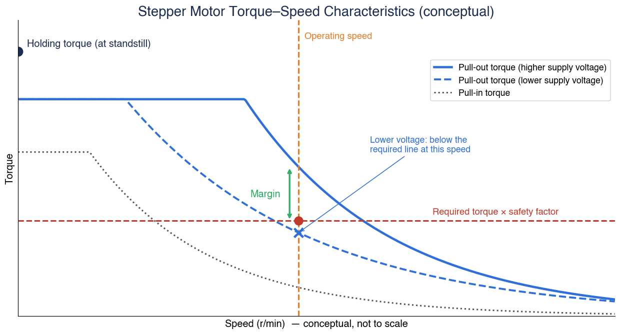
The figure above is a conceptual diagram with no scale. What you want to check in selection is whether, at the operating speed (vertical dashed line), the pull-out torque curve lies above “required torque × safety factor” (horizontal dashed line), and how much margin there is between them. Oriental Motor’s materials also explain that, in selection, you should confirm that the required torque falls inside the pull-out torque curve.
Oriental Motor further writes that the torque-speed characteristics are determined by the combination of motor and driver, and are greatly affected by the type of driver being used. Even with the same motor, the curve changes if the driver or supply voltage changes. The next section looks at why.
Supply Voltage and Driver Change Torque in the High-Speed Range
A stepper motor produces torque by passing current through its windings. As speed rises, the interval between pulses becomes shorter, and the motor switches to the next phase before the winding current has fully risen, so torque falls.
According to Oriental Motor’s technical reference, constant-current chopper drive compensates for this. A DC voltage far higher than the motor’s rated voltage is chopped so that the rated current flows. All of the company’s package products are described as using constant-current drive.
The same reference explains the differences due to supply voltage as follows.
- A driver with 24 VDC input applies 24 VDC to the motor
- A driver with 100-115 VAC / 200-230 VAC input applies about 162 VDC after rectification (with some exceptions)
- The higher the applied voltage, the faster the current rises, which produces differences in torque characteristics in the high-speed range. AC input products perform better over a wide speed range
A mismatch that often occurs in selection is choosing a motor by looking at the catalog curve for an AC input driver, while the actual machine combines it with a 24 VDC input driver. In the high-speed range, this alone can wipe out the margin against pull-out torque.
For this reason, the calculation sheet and the RFP should require that not only the motor model, but also the driver model and the supply voltage are fixed, and the torque-speed characteristics of that specific combination are used as the basis. If a machine builder’s calculation sheet only says “required torque X N·m against holding torque Y N·m,” check which driver and which voltage the curve was for, and the pull-out torque at which speed it was compared against.
Stepper Motor Selection Procedure: From Motion Profile to Required Torque
Oriental Motor’s technical reference sets out the motor selection procedure as follows.
- Determine the drive mechanism, approximate dimensions, travel distance and positioning period
- Confirm the required specifications (stopping accuracy, position holding, speed range, supply voltage, resolution, durability, etc.)
- Calculate the load torque, load inertia and speed converted to the motor shaft
- Select the type of motor (AC, brushless, stepper, etc.)
- Make the final decision after confirming that all requirements, such as mechanical strength, acceleration time and acceleration torque, are met
Applied to stepper motor selection, this becomes the flow shown in the figure below.
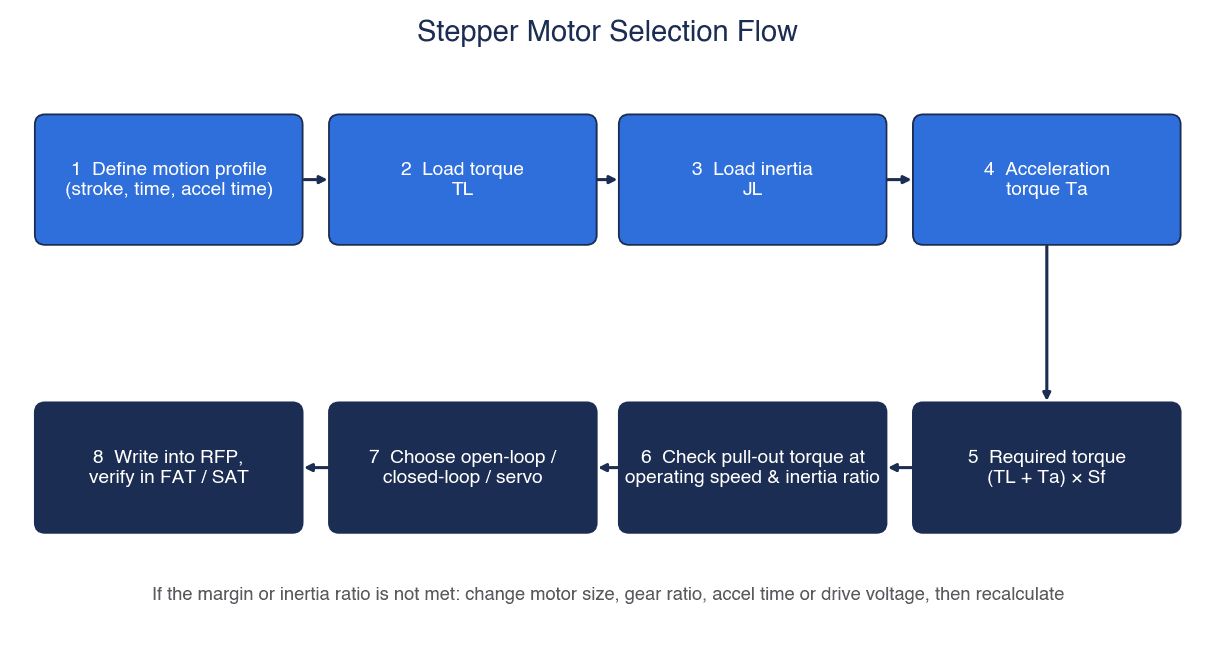
- Define the motion profile: stroke, positioning time, acceleration/deceleration time. In Oriental Motor’s calculation example, an acceleration/deceleration time of “25% of the positioning period is appropriate.” This is a guideline from the company’s worked example, not a specified value.
- Calculate the load torque TL: the torque needed to move the load at constant speed against friction and gravity.
- Calculate the load inertia JL: the moment of inertia of the screw shaft, table, workpiece and so on, converted to the motor shaft.
- Calculate the acceleration torque Ta: the torque needed to raise the speed within the acceleration/deceleration time.
- Obtain the required torque: (TL + Ta) × safety factor Sf.
- Check the pull-out torque at the operating speed and the inertia ratio: judge using the curve for a fixed driver and supply voltage.
- Choose the approach: open-loop, closed-loop or servo.
- Write it into the RFP and verify it in FAT/SAT: keep the calculation conditions and the basis for the decision in writing.
Selection of the drive mechanism itself, such as how to decide the lead and shaft diameter of a ball screw, is covered in our ball screw selection guide, and belt drives are covered in our timing belt selection article. Motor selection starts once the conditions of these mechanisms have been decided.
Stepper Motor Torque Calculation: Load Torque, Moment of Inertia and Acceleration Torque Formulas
Here, the formulas in Oriental Motor’s technical reference are rewritten in SI units (the company’s US materials use oz-in units, but the form of the formulas is the same).
Symbols
| Symbol | Meaning | Unit |
|---|---|---|
| F | Axial load | N |
| FA | External force | N |
| m | Mass of table + workpiece | kg |
| g | Gravitational acceleration | m/s² |
| α | Inclination angle (horizontal 0°, vertical 90°) | ° |
| μ | Friction coefficient of the sliding surface | – |
| PB | Ball screw lead | m |
| η | Efficiency | – |
| μ0 | Internal friction coefficient of the preloaded nut | – |
| F0 | Preload | N |
| D | Diameter of pulley or pinion | m |
| ρ | Density of material | kg/m³ |
| LB, DB | Length and diameter of the screw shaft | m |
| J0 | Rotor moment of inertia | kg·m² |
| JL | Load moment of inertia (converted to motor shaft) | kg·m² |
| θs | Step angle | ° |
| f1, f2 | Starting pulse speed, operating pulse speed | Hz |
| t0, t1 | Positioning time, acceleration/deceleration time | s |
| Sf | Safety factor | – |
Load torque
- Axial load: F = FA + m·g·(sinα + μ·cosα)
- Ball screw load torque: TL = F·PB / (2π·η) + μ0·F0·PB / (2π)
- Belt or rack-and-pinion load torque: TL = F·D / (2·η) (if there is a reduction ratio i, divide further by i)
The second term in the ball screw formula comes from the internal friction of the preloaded nut, and Oriental Motor’s calculation example sets the preload as F0 = F/3. For the details of the symbols in the belt formula, check the figure in the original material before using it.
Moment of inertia
- Cylinder (ball screw shaft): JB = (π/32)·ρ·LB·DB⁴
- Linear-motion table + workpiece converted to the motor shaft: JT = m·(PB/2π)²
- Load inertia: JL = JB + JT (add couplings and other parts if present)
Speed and acceleration torque
- Operating pulse speed: f2 = (A − f1·t1) / (t0 − t1) (A is the number of operating pulses)
- Rotation speed: N = f2 × (θs/360) × 60 [r/min]
- Acceleration torque: Ta = (J0 + JL) × (π·θs/180) × (f2 − f1) / t1
- Required torque: TM = (TL + Ta) × Sf
- Acceleration/deceleration rate: TR = t1 / (f2 − f1) (calculated with the pulse speed converted to full step)
- Inertia ratio: JL / (J0·i²) (with a gear, divide by the square of the reduction ratio i)
- Approximation of the maximum starting frequency with load inertia: f = fs / √(1 + JL/J0)
The inertia of a ball screw shaft varies greatly with the lead, shaft diameter and shaft length, and the coupling inertia is added on top. For how to choose a coupling, see our shaft coupling selection article.
Model Calculation: Horizontal Ball Screw Axis, 20 kg, 10 mm Lead
From here, we use the formulas from the previous section to calculate torque. All of the following numbers are hypothetical values for illustration. As an example motor, we use only the rotor inertia of 90 g·cm² (= 90×10⁻⁷ kg·m²) and the holding torque of 450 mN·m from the specification table of the MinebeaMitsumi H17PMK442BSTDCN (42 mm square, 1.8°, bipolar, 0.90 A). There is no intention to recommend this motor, and its pull-out torque value has not been confirmed in this calculation.
Assumptions (all hypothetical)
| Symbol | Assumed value | Notes |
|---|---|---|
| m | 20 kg | Table + workpiece |
| μ | 0.05 | Friction coefficient of the sliding surface (assumed to be the same value as in Oriental Motor’s calculation example) |
| η | 0.9 | Ball screw efficiency (same as above) |
| μ0 | 0.3 | Internal friction coefficient of the preloaded nut (same as above) |
| F0 | F/3 | Preload (as set in the company’s calculation example) |
| PB | 10 mm | Lead |
| DB | 15 mm | Screw shaft diameter |
| LB | 500 mm | Total screw length |
| ρ | 7.9×10³ kg/m³ | Iron |
| Stroke | 150 mm | – |
| t0 | 1.0 s | Positioning time |
| t1 | 0.25 s | Acceleration/deceleration time (25% of t0) |
| f1 | 0 Hz | Starting pulse speed |
| θs | 1.8° | Full-step equivalent |
| Mechanism | Horizontal, direct drive | Coupling inertia ignored |
Calculation results
| No. | Item | Calculation | Result |
|---|---|---|---|
| 1 | Axial load F | 20 × 9.807 × 0.05 | 9.807 N |
| 2 | Load torque TL | 0.017343 + 0.001561 | 0.0189 N·m |
| 3 | Screw shaft inertia JB | (π/32) × 7,900 × 0.5 × 0.015⁴ | 196.3×10⁻⁷ kg·m² |
| 4 | Converted inertia of table + workpiece JT | 20 × (0.010/2π)² | 506.6×10⁻⁷ kg·m² |
| 5 | Load inertia JL | 196.3 + 506.6 (×10⁻⁷) | 702.9×10⁻⁷ kg·m² |
| 6 | Inertia ratio JL/J0 | 702.9 / 90 | 7.81 |
| 7 | Number of operating pulses A | 150 / 10 × 200 | 3,000 pulses |
| 8 | Operating pulse speed f2 | 3,000 / (1.0 − 0.25) | 4,000 Hz |
| 9 | Rotation speed N | 4,000 × 1.8/360 × 60 | 1,200 r/min |
| 10 | Acceleration torque Ta | (90 + 702.9)×10⁻⁷ × 502.65 | 0.0399 N·m |
| 11 | TL + Ta | 0.0189 + 0.0399 | 0.0588 N·m |
| 12 | Required torque (Sf = 1.5) | 0.0588 × 1.5 | 0.088 N·m |
| 13 | Required torque (Sf = 2) | 0.0588 × 2 | 0.118 N·m |
| 14 | Acceleration/deceleration rate TR | 250 ms / 4 kHz | 62.5 ms/kHz |
| 15 | Reduction factor of starting frequency | 1 / √(1 + 7.81) | 0.337 |
The 502.65 in No. 10 is the angular acceleration (rad/s²), obtained as (π × 1.8/180) × 4,000 / 0.25. Converting 1,200 r/min to angular velocity gives about 125.66 rad/s, and dividing this by 0.25 seconds gives the same value. The table speed is 1,200 / 60 × 10 = 200 mm/s, and the travel distance of the trapezoidal motion, 200 mm/s × 0.75 s = 150 mm, matches the stroke.
What the calculation tells us
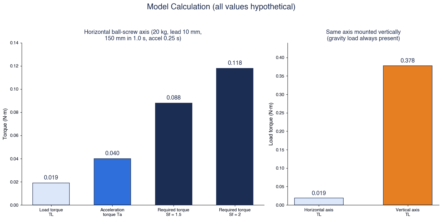
First, on a horizontal axis, the acceleration torque is larger than the load torque. In this calculation, the acceleration torque of 0.040 N·m is about twice the load torque of 0.019 N·m. On a horizontal ball screw axis with low friction, the required torque is determined less by “how heavy the load is” than by “how quickly it accelerates and decelerates” and “how large the inertia is.” If the maximum speed stays the same, shortening the acceleration/deceleration time increases the acceleration torque in inverse proportion.
Second, do not compare against holding torque. The required torque of 0.088 to 0.118 N·m (Sf 1.5 to 2) looks like only about 20 to 30% of the example motor’s holding torque of 0.45 N·m. However, what should be compared is the pull-out torque at 1,200 r/min (4 kHz at full step). That value has to be read from the torque-speed characteristics for the driver and supply voltage conditions you will use. You cannot say it is fine just because it is 20 to 30% of the holding torque.
Third, check the inertia ratio and the starting frequency as well. An inertia ratio of 7.81 can be read as falling within Oriental Motor’s reference values described later (RK series 10, αSTEP 30). However, the inertia ratio recommended by the manufacturer of the example motor was not confirmed in this research. In addition, with load inertia, the calculation shows the maximum starting frequency falling to about 34% of the no-load value (factor 0.337), so the speed at which the motor can start without acceleration drops considerably.
Reference: the same axis mounted vertically. Using the same formulas with α = 90°, F = 20 × 9.807 = 196.14 N and TL = 0.3469 + 0.0312 = 0.378 N·m, about 20 times the horizontal value (the preload F0 = F/3 is an assumption borrowed from how the company’s worked example sets it). On a vertical axis, the gravity load acts at all times, so the way torque is considered and the method of holding both change. This is covered later in the section on vertical axes.
Stepper Motor Inertia Ratio and Safety Factor: How to Read Manufacturer Reference Values
Inertia ratio and safety factor are not “values fixed by the industry,” but reference values that each manufacturer gives for its own products. The following values can be read from a table in Oriental Motor’s technical reference.
| Item | αSTEP (AS series) | RK series (5-phase) | Notes in the source |
|---|---|---|---|
| Safety factor Sf | 1.5 to 2 | 2 | Oriental Motor reference values |
| Inertia ratio | 30 | 10 (when not a geared type) | The company’s Selection Tips also show 30 Max. as the reference value for both Step-Servo and Stepper |
The same reference explains that a large inertia ratio increases overshoot and undershoot at starting and stopping, affects the starting time and settling time, and under some conditions can make operation impossible. When the reference value is exceeded, it recommends a geared motor. Because the inertia ratio formula is JL / (J0·i²), the load-side inertia appears smaller by the square of the reduction ratio i. In a comparison example of positioning a large inertial load in a short time, the company also shows that a geared motor can shorten the positioning time. Types of reducers and how to choose them are organized in our gearbox reducer selection article.
As the party receiving the calculation sheet, there are three points to keep in mind.
- Which company’s, and which series’ reference value is it? Even if the sheet simply says “inertia ratio 10 or less,” it is not a valid basis if that is a value for another manufacturer or another series.
- Where was the safety factor applied? In the form of Oriental Motor’s formula, it is applied to the sum of TL and Ta. Check that it has not been applied only to the load torque with the acceleration torque left out.
- Does it allow for the reduction in starting frequency? In the calculation in the previous section, the factor was 0.337. If the starting pulse speed f1 is set to something other than zero, check whether that value is lower than the starting frequency reduced by the load inertia.
Missed Steps: Causes and Stall Prevention
A missed step (misstep) is a phenomenon in which the motor cannot follow the pulses, so the commanded position and the motor’s actual position diverge. When running open-loop, neither the driver nor the controller knows about that deviation.
Main causes
Here, the causes are organized from Oriental Motor’s technical reference and other sources.
| Cause | Explanation in the source |
|---|---|
| Following delay due to inertia | With instantaneous starting and stopping, the inertia of the rotor and load causes lag and lead at the motor shaft, and beyond a certain point the motor cannot follow the pulses and misses steps (Oriental Motor) |
| Acceleration too steep or insufficient torque | If the required torque exceeds the pull-out torque at the operating speed, the motor cannot run (from Oriental Motor’s definition) |
| Large inertia ratio | Overshoot and undershoot increase, settling time is affected, and operation may become impossible (Oriental Motor) |
| Resonance | For 2-phase stepper motors, the area around 100 to 200 Hz is a resonance area, and 5-phase motors have a lower level of resonance (Oriental Motor’s description of its own products) |
| Load variation | Stepper motors do not handle dynamic load changes well (Parker technical knowledge base) |
| Torque drop in the high-speed range | Torque drops sharply at high speeds, so caution is needed about missed steps due to overload, heat and vibration (MinebeaMitsumi FAQ) |
The resonance area of 100 to 200 Hz is a value Oriental Motor gives for its own 2-phase products, and it is not common to all manufacturers.
Approach to countermeasures
- Review acceleration and deceleration: lengthening the acceleration/deceleration time lowers the acceleration torque. In the acceleration torque formula, if the maximum speed is the same, the acceleration torque is inversely proportional to the acceleration/deceleration time.
- Lower the inertia ratio: use a geared motor, review the lead, or use a motor with larger rotor inertia (in this case the acceleration torque also increases, so recalculate the required torque).
- Avoid or reduce resonance: set speeds so that the motor does not run in the resonance area for long. Oriental Motor describes microstepping as a technology that achieves low resonance and low noise in the low-speed range. A 5-phase motor is also an option.
- Secure margin at the operating speed: review the driver and supply voltage to raise the pull-out torque curve.
- Make it detectable: detect missed steps with an encoder, or use a closed-loop approach. Parker’s knowledge base states that “an encoder can be used for stall detection,” explaining that if the encoder value does not change while a command is being issued, this can indicate a stall.
Items 1 to 4 make missed steps less likely to occur, and item 5 lets you notice when they do occur. The basic approach is to have both in place. How to choose an encoder is explained in our rotary encoder selection article.
Microstepping: Resolution and Accuracy Are Different Things
Microstepping is a technology in which the driver finely controls the winding current to divide the basic step angle into even smaller steps. Oriental Motor explains that its 5-phase drivers can divide 0.72° into 1/1 to 1/250. In Lin Engineering’s example, dividing a 1.8° motor by 256 gives 51,200 microsteps per revolution (about 0.007° per microstep).
What is easily confused here is resolution versus accuracy. Lin Engineering’s technical article puts it clearly: “During microstepping, you are not necessarily increasing the accuracy, but you are increasing the resolution.” Even if the increments of angle you can command become finer, that does not mean the motor will actually stop accurately at that position.
Converted to the screw
Consider a ball screw with the same 10 mm lead as in the model calculation and a 1.8° motor.
| Item | Calculation | Value |
|---|---|---|
| Full-step resolution | 10 mm / 200 | 0.05 mm/step |
| 1/10 microstep resolution | 0.05 mm / 10 | 0.005 mm/step |
| Stopping accuracy of ±0.05° (Oriental Motor’s no-load value) converted to the screw | 0.05 / 360 × 10 mm | about ±1.4 µm |
| About ±5% of one step (Lin Engineering’s error for standard products) converted to the screw | 1.8° × 5% / 360 × 10 mm | about ±2.5 µm |
This conversion translates only the angular error of the motor alone into screw travel, and does not include the lead error of the ball screw, backlash, or the angular displacement caused by frictional load. The positioning accuracy of the machine as a whole is often dominated by errors on the mechanism side, so do not assume that “raising the microstep division will raise the accuracy of the machine.”
Effect on pulse frequency
Raising the resolution with microstepping raises the pulse frequency needed for the same rotation speed. The 1,200 r/min in the model calculation is 4 kHz at full step, but if you were to command it with a division equivalent to 1/100, it would be 400 kHz. As described later, the maximum input pulse frequency of the driver changes with the output method on the PLC side, so the division and the output method should be decided together.
Stopping Accuracy and Unidirectional Positioning
Catalog stopping accuracy is almost always a conditional value. Oriental Motor’s technical reference explains it as follows.
- Under no-load conditions, a stepper motor has an angular accuracy within 3 arc minutes (0.05°)
- The static angle error is a value under no-load conditions; in actual applications there is frictional load, so an angular displacement according to the angle-torque characteristics is added
- In reciprocating operation, that displacement is doubled over the round trip
- If high stopping accuracy is required, positioning from one direction is recommended
The table in the company’s Selection Tips shows stopping accuracy for each product. For example, the AZ series is given as ±0.083° to ±0.05° depending on the model, and the standard PKP 2-phase as ±0.05°, with a footnote stating that “this is the value at full step and no load (this value will vary depending on load).” For 5-phase motors there is also a description of “±3 arc minutes with no load.”
| What to check | Reason |
|---|---|
| Is it a no-load value or a value under load? | Frictional load adds angular displacement |
| Is it a full-step value? | It is not necessarily the value during microstepping |
| Unidirectional positioning or reciprocating? | Displacement doubles when reciprocating |
| Motor alone or the machine as a whole? | Mechanism errors are separate |
In the RFP, do not let the supplier write only “stopping accuracy ±X°”; require them to state the four conditions above alongside it. In acceptance testing as well, there is no point comparing with the catalog value unless the measurement is made under the same conditions.
The Closed-Loop Stepper Motor Option
A closed-loop stepper motor is an approach in which a position sensor such as an encoder is attached to the motor and control is performed while watching the difference between the commanded position and the actual position. The following are “vendor claims” based on the manufacturers’ published materials.
Oriental Motor αSTEP (description of the AS series generation)
According to the company’s technical reference, αSTEP has a built-in rotor position sensor at the rear end of the motor shaft and calculates the deviation between commanded and actual positions with a deviation counter.
- When the deviation is less than 1.8°, the motor runs in open mode
- When the deviation reaches 1.8° or more, it switches to closed mode and is controlled with excitation that produces maximum torque relative to the rotor position
The company explains that this approach does not miss steps, and says it frees the motor from constraints due to starting pulse speed, acceleration/deceleration rate and inertia ratio. However, this is a vendor claim. Because there may be situations in which the motor cannot recover its position if overload continues, TOMAS TECH recommends not reading it as “holds position under any load,” but rather viewing it as a mechanism that stops with an alarm when the deviation becomes large, in other words, one that allows abnormalities to be detected. The company’s AZ series is classified as a “closed loop absolute type” with a battery-free mechanical absolute sensor.
Applied Motion Products StepSERVO
According to the company’s product news published in a trade magazine (2019), StepSERVO integrates a step motor, drive, encoder, controller and closed-loop servo software in one product. It is said to automatically reduce motor current when the load no longer demands torque, consuming less power than conventional step systems and running cooler and more quietly. There is an IP65 version, and it is said to support CANopen, EtherNet/IP and Modbus RTU/TCP.
Confirm the difference in approach in the RFP
Parker’s knowledge base explains that steppers with encoders include “methods that correct at the end of a move” and “methods that apply feedback at all times.” Because the content differs even under the same “closed-loop” label, the RFP should require answers to the following.
- Continuous feedback, or correction after stopping?
- Behavior when the deviation becomes large (alarm stop, correction limit, etc.)
- How the alarm is returned to the PLC
Stepper vs Servo Motor: Decision Criteria
The differences between stepper motors and servo motors are organized below from Parker’s knowledge base and the descriptions in each company’s materials. Prices are not covered.
| Criterion | Open-loop stepper | Closed-loop stepper | Servo |
|---|---|---|---|
| Position confirmation | None (cannot notice missed steps) | Confirmed with a sensor (vendor claim) | Confirmed continuously with an encoder |
| Torque in the high-speed range | Falls greatly with speed (MinebeaMitsumi) | Depends on the approach and product | Check with the product’s rated and maximum torque |
| At standstill | Holds position very well (Parker). Holding only while powered | Depends on the product (only while powered) | Held by control (only while powered) |
| Gain tuning | No tuning necessary (Parker) | Depends on the product | Tuning of torque, speed and position loops required (Parker) |
| Heat | Case temperatures can be hot. Can be reduced at standstill with current reduction (Parker) | Some products lower current according to load (vendor claim) | Depends on the product |
| Values checked in selection | Pull-out torque curve, inertia ratio | Same as left + behavior on deviation | Maximum instantaneous torque, effective (RMS) torque, permissible load inertia (Oriental Motor) |
Parker’s knowledge base also includes an example of high-speed torque comparing specific products, but because it is a comparison of specific products, this article does not cite those figures as general values for steppers and servos. What can be said in general is, as MinebeaMitsumi’s FAQ states, that stepper motor torque drops sharply at high speeds.
The decision guidelines can be organized as follows.
- Low to medium speed, stable load, and holding the stop position is important: an open-loop stepper is a candidate. If missed-step detection is needed, add an encoder.
- Load varies and you do not want missed steps to go unnoticed: a closed-loop stepper is a candidate. Fix the behavior on deviation in the RFP.
- Torque is needed in the high-speed range, load variation is large, or acceleration and deceleration are severe: a servo is a candidate. Allow for the man-hours for gain tuning.
How to choose between servo and inverter is covered in detail in our servo control vs inverter control article, and how to procure servo axes and run acceptance testing in our servo control procurement and FAT/SAT guide.
Vertical Axes, Holding During Power Failure and Electromagnetic Brakes
A stepper motor has holding torque while it is stopped, but only while it is powered. Oriental Motor’s RK series materials show in a diagram that while the All Windings Off (A.W.OFF) input is active, the motor current is cut and there is no holding power, and that with a setting that automatically cuts current on an overheat signal, the result is also “Stop (No holding power).”
In other words, on a vertical axis the load can fall in situations such as the following.
- Power failure
- When the driver power is cut by an emergency stop
- When all windings are switched off (C.OFF) for maintenance
- When the driver cuts current due to overheating or similar
In the model calculation too, making the axis vertical gives a load torque of 0.378 N·m, about 20 times the horizontal value, and that gravity load acts at all times.
Oriental Motor uses a non-excitation type electromagnetic brake that holds automatically in the event of a power failure or similar. For the company’s AS series, the electromagnetic brake power supply is 24 VDC ±5%, 0.3 A or more (0.1 A or more for the AS46), and the company instructs that it be kept independent of the driver’s signal power supply.
An electromagnetic brake is a component for holding position, and is not intended to be used as a braking device to stop a rotating load. In the RFP and FAT, check the following points.
- Is it a non-excitation type?
- The brake power supply circuit (is it independent of the driver’s signal power supply?)
- The timing of brake release and excitation (is the sequence such that the axis does not drop at the moment of switching?)
- Does the axis stay in place during a power failure, an emergency stop and C.OFF?
How to choose brake torque and response time is explained in our electromagnetic brake selection article.
Heat, Case Temperature, Current Reduction at Standstill and Operating Duty
Case surface temperature
Regarding the surface temperature of stepper motors, Oriental Motor’s FAQ explains that the motor can be used if the motor case surface temperature is 100°C or less. The windings have Class B insulation (allowable 130°C), and a temperature difference of about 30°C is assumed between the inside and the case surface, which is why the surface limit is 100°C. The AZ series is to be used with a case surface temperature of 80°C or less, and an overheat alarm is said to occur when the sensor temperature reaches 85°C or more. From the standpoint of bearing life, the company also recommends mounting the motor on a metal plate with good heat conduction and using it at as low a temperature as possible.
These are values for the company’s products. Check the limits for other manufacturers’ products in their own materials. Parker’s knowledge base also notes that with stepper motors, “case temperatures can be hot.” Being hot to the touch does not necessarily mean something is wrong, but there is value in measuring it during acceptance testing and keeping a record. Because measured temperatures depend on the ambient temperature, record the ambient temperature as well.
Current reduction at standstill
A stepper motor keeps current flowing to hold position even while stopped, so it generates heat even at standstill. According to Oriental Motor’s technical reference, the company’s automatic current cutback function reduces motor current to about 50% (about 40% for the 2-phase CSK and UMK series) within about 0.1 seconds after pulse input stops, suppressing heat in the motor and driver. Other companies have functions based on the same idea under names such as “current foldback” (Parker).
A point to note is that lowering the current also lowers the holding torque at standstill. The RK series description states that the holding torque at standstill is proportional to the standstill current set with a switch. On vertical axes and on axes subject to external force while stopped, check whether the holding torque after current reduction is sufficient.
Operating duty
Oriental Motor’s technical reference states: “A stepping motor is not intended to be run continuously with rated current. Lower than 50% running duty cycle is recommended.” For axes that keep moving for most of the cycle, consider approaches other than stepper motors as well.
Connection to PLCs and Host Systems: Pulse Trains and Networks
Pulse train input
When positioning from a PLC with a pulse train, match the PLC output method with the driver input method. On the product page for Oriental Motor’s AZD-CED (AZ series, EtherCAT compatible, AC input), pulse input is 2 photocoupler inputs, and the maximum input pulse frequency is as follows.
| PLC-side output method | Maximum input pulse frequency (AZD-CED value) |
|---|---|
| Line driver output | 1 MHz (50% duty) |
| Open collector output | 250 kHz (50% duty) |
Even with the same driver, the limit differs by a factor of 4 depending on the output method on the PLC side. As seen in the microstepping section, commanding 1,200 r/min with a division equivalent to 1/100 requires 400 kHz; in the case of this product, the 250 kHz of open collector is not enough, while the 1 MHz of line driver is within range. These are values for this one product, so in practice confirm them with the specifications of the driver you adopt and the PLC’s positioning unit. In Oriental Motor’s AS series connection example, a line driver equivalent to 26C31/26C32 and twisted-pair wire are used.
Network connection
Instead of a pulse train, commands can also be issued over a field network. The AZD-CED supports EtherCAT as its field network, with a degree of protection of IP10 and a control power supply of 24 VDC ±5% 0.25 A (0.5 A with electromagnetic brake). As mentioned above, StepSERVO is advertised as supporting CANopen, EtherNet/IP and Modbus RTU/TCP. Degrees of protection vary greatly by product, as with the AZD-CED (driver, IP10) and the IP65 version of StepSERVO (integrated motor), so check them together with the dust and moisture conditions at the installation site.
Homing
How the home position is obtained is another item to decide in the RFP. The AS series is said to be able to use its Timing signal, 50 pulses per motor revolution, for high-precision detection of the home position. The AZ series is said to have a battery-free mechanical absolute sensor.
For the basics on the PLC side, see also our article on what a PLC is and its types.
Automation Investment Trends in Thailand, and Why Now
Investment applications related to automation and robotics continue in Thailand. Because the scope and time period differ from source to source, they are shown side by side below. All BOI figures are application amounts for investment promotion, not actual investment amounts or approved amounts.
| Indicator | Value | Scope and period | Source |
|---|---|---|---|
| BOI investment promotion applications (total) | About 1.47 trillion baht, 1,299 projects, +37% year on year | January to June 2026, application basis | BOI Press Release No. 117/2569 |
| Of which, machinery, automation and robotics sector | About 13.1 billion baht, 82 projects | Same as above | Same as above |
| Smart and Sustainable Industry measure (machinery upgrades, digitalization, automation/robot adoption) | 132 projects, about 17.2 billion baht | Same as above | Same as above |
| FDI applications from Japan | About 32.8 billion baht, 123 projects | Same as above | Same as above |
| BOI investment promotion applications (total) | 1.87 trillion baht, 3,370 projects | Full year 2025, application basis | BOI Press Release No. 124/2569 |
| New industrial robot installations worldwide | 603,307 units (+11%) | World, 2025 | IFR World Robotics 2026 |
| New installations in Asia | 457,315 units (76% of new installations worldwide) | Asia, 2025 | Same as above |
| New installations in China | 354,226 units (+20%) | China, 2025 | Same as above |
In the press release announcing its full-year 2025 results (No. 124/2569, August 4, 2026), the BOI lists “Automation and Robotics” as one of its six strategic sectors. The IFR forecasts 655,000 new installations worldwide in 2026. The IFR Executive Summary and press release do not state unit numbers for Thailand alone.
Why review stepper motor selection now?
As new automation equipment is installed and existing equipment is upgraded, the number of small axes for conveying, positioning and indexing also increases. Stepper motors are used in many of them, but selection is often left entirely to the machine builder, and in many cases the basis for the selection does not remain with the plant. When missed steps occur after startup, or when an upgrade calls for choosing a substitute because “the same model is no longer available,” no judgment can be made without a calculation sheet. There is value in setting up a mechanism to receive the basis for selection in writing now, at the stage of writing the RFP for new equipment.
12 Items to Include in the RFP
We have organized into 12 items what you will want to include in the RFP when ordering machines or units that use stepper motors. At the core is “having the supplier document under what conditions, and against what, the motor was selected.”
| No. | Item | Examples of what to include |
|---|---|---|
| 1 | Operating conditions | Load mass, stroke, positioning time, acceleration/deceleration time, mounting orientation (horizontal, vertical, inclined) |
| 2 | Mechanism conditions | Ball screw lead, shaft diameter and length, belt and pulley diameter, reduction ratio, friction coefficient, efficiency |
| 3 | Calculation sheet | Calculation process for load torque, load inertia, acceleration torque and required torque, and the source of the formulas used |
| 4 | Safety factor and inertia ratio | Safety factor and inertia ratio adopted, and for each, “which company’s and which series’ reference value” |
| 5 | Margin against pull-out torque | Comparison of pull-out torque at the operating speed with required torque, using a curve that states the driver model and supply voltage |
| 6 | Conditions for stopping accuracy | No load or under load, full step or not, unidirectional positioning or not, motor alone or the machine as a whole |
| 7 | Control approach | Open-loop / closed-loop / servo. If closed-loop, continuous feedback or correction after stopping, and behavior on deviation |
| 8 | Command method | Pulse train (line driver / open collector) and maximum input pulse frequency, microstep division, type of network |
| 9 | Current and holding at standstill | Whether standstill current reduction is used and the holding torque after reduction, how All Windings Off is used |
| 10 | Holding on vertical axes | Whether a non-excitation type brake is fitted, the brake power supply circuit, the sequence of release and excitation |
| 11 | Temperature and duty | Case surface temperature limit (manufacturer value), operating duty, ambient temperature conditions |
| 12 | Signals on abnormality and maintenance | Content of alarm outputs and how they are returned to the PLC, homing method, spare parts, supply and support within Thailand |
How detailed the “calculation sheet” and “margin against pull-out torque” can be differs from one machine builder to another. If they are written into the RFP from the start, they can be compared at the quotation stage.
Acceptance Testing (FAT/SAT) Checklist
In acceptance testing, confirm not only that “it ran,” but also the conditional values under the same conditions. The numerical pass/fail criteria should be decided from the manufacturer values and your own company standards and written into the RFP and the test plan in advance.
| Check item | Test method | How to set the pass/fail criteria |
|---|---|---|
| Continuous operation with the motion profile | Run repeatedly with the actual load, stroke and positioning time, and check the deviation between commanded and actual position | Decide the allowable deviation in-house |
| Presence of missed steps | After a specified number of operations, check for position deviation with an external measuring instrument or an encoder | Decide in-house whether to require zero deviation, etc. |
| Margin confirmation | Make conditions more severe, for example by shortening the acceleration/deceleration time below the planned value, and record how much margin there is | Decide the required margin in the RFP |
| Stopping accuracy | Measure under the conditions set in the RFP (with or without load, unidirectional positioning, etc.) | Conditional manufacturer value and in-house standard |
| Case surface temperature | Run at the actual duty and measure once the temperature has stabilized. Also record the ambient temperature | Manufacturer value (e.g., Oriental Motor 100°C or less, AZ series 80°C or less) |
| Holding at standstill | After current reduction, check whether the position shifts under external force applied while stopped | As specified |
| Fall prevention on vertical axes | Simulate power failure, emergency stop and C.OFF, and check that the axis does not fall and the brake sequence | No falling |
| Closed-loop behavior on deviation | Apply load intentionally and check the alarm and correction behavior | As specified |
| Signals with the PLC | Check alarms, homing and operation near the upper limit frequency of the pulse input | As specified |
FAT (factory acceptance test) is carried out at the machine builder’s factory, and SAT (site acceptance test) at your own plant in Thailand. Since ambient temperature and power supply conditions change on site, it is safer to repeat the temperature and margin checks in SAT as well.
Frequently Asked Questions
What value should you look at first in stepper motor selection?
Not holding torque, but pull-out torque at the operating speed. Holding torque is a value at standstill, and once the motor rotates, the torque it can produce falls as speed increases. Because the pull-out torque curve changes with the driver and supply voltage, confirm with the curve for the combination you will adopt that it exceeds required torque × safety factor. Check the inertia ratio as well.
How do you do a stepper motor torque calculation?
Define the motion profile (stroke, positioning time, acceleration/deceleration time), calculate the load torque TL, load inertia JL and acceleration torque Ta in turn, and obtain the required torque as (TL + Ta) × safety factor. The formulas are summarized in the section “Stepper Motor Torque Calculation: Load Torque, Moment of Inertia and Acceleration Torque Formulas” above. In this article’s hypothetical calculation, the acceleration torque on a horizontal ball screw axis came out at about twice the load torque.
What causes missed steps, and how can they be prevented?
The main causes are following delay due to steep acceleration or inertia, insufficient torque at the operating speed, a large inertia ratio, resonance and load variation. Countermeasures include lengthening the acceleration/deceleration time, lowering the inertia ratio with a geared motor or similar, avoiding the resonance area, using microstepping or a 5-phase motor, and reviewing the driver and supply voltage. Because missed steps cannot be noticed in open-loop operation, also consider detection with an encoder or a closed-loop approach.
What is the difference between a stepper motor and a servo motor?
A stepper motor is basically controlled open-loop, with the angle determined by the number of pulses; it needs no gain tuning and is good at holding at standstill. On the other hand, its torque drops greatly at high speed, and it cannot notice by itself when it misses steps. A servo motor continuously confirms its position with an encoder and requires gain tuning. The values checked also differ: for a stepper, the pull-out torque curve and inertia ratio; for a servo, the maximum instantaneous torque, effective torque and permissible load inertia.
Does a closed-loop stepper motor never miss steps?
Some manufacturers describe their products as “not missing steps,” but it is safer not to read this as meaning the motor can hold its position under any load. In practice, it is better to think of it as a mechanism that detects and corrects position deviation, and stops with an alarm if the deviation becomes large, in other words, an approach that “lets you notice missed steps.” Confirm in the RFP whether it uses continuous feedback or correction after stopping, and how it behaves when the deviation is large.
Does microstepping improve accuracy?
Resolution increases, but accuracy does not increase in proportion. Lin Engineering also explains that microstepping does not necessarily increase accuracy, but increases resolution. In addition, the positioning accuracy of the machine as a whole includes the lead error of the ball screw, backlash and displacement due to frictional load. If high stopping accuracy is required, also consider positioning from one direction.
How much does a stepper motor cost?
Costs vary greatly depending on the number of axes, the combination of motor and driver, open-loop or closed-loop, pulse train or network, whether there is a brake, and the scope of calculation sheets and testing, so no general figure can be given. The reliable approach is to fix the operating conditions and check items in the RFP and then obtain and compare quotations from several companies.
Summary
- Stepper motor selection is decided not by holding torque, but by pull-out torque at the operating speed, driver and supply voltage, and by acceleration torque and inertia ratio
- Torque-speed characteristics are determined by the combination of motor and driver. Torque in the high-speed range differs between AC input drivers (about 162 VDC applied, with some exceptions) and 24 VDC input (Oriental Motor)
- In a hypothetical calculation (horizontal ball screw axis, 20 kg, 10 mm lead, 150 mm in 1.0 s), the acceleration torque of 0.040 N·m is about twice the load torque of 0.019 N·m. The required torque is 0.088 to 0.118 N·m (Sf 1.5 to 2), and what it should be compared against is the pull-out torque at 1,200 r/min
- Safety factor and inertia ratio are manufacturer reference values (in Oriental Motor’s example, Sf 1.5 to 2, inertia ratio RK 10 / αSTEP 30). Require the calculation sheet to state which company’s and which series’ values they are
- Microstepping increases resolution, but accuracy does not increase in proportion. Stopping accuracy is a value tied to conditions such as no load, full step and unidirectional positioning
- Open-loop operation cannot notice missed steps. Closed-loop is an option that turns missed steps into detection, correction and alarms; confirm the difference in approach in the RFP
- A vertical axis can hold only while powered. Check the non-excitation type brake, its power supply circuit, and the sequence of release and excitation
- Require the RFP to include the calculation sheet, the margin against pull-out torque, the conditions for stopping accuracy, the command method, the standstill current, and temperature and duty, and verify them in FAT/SAT under the same conditions
TOMAS TECH supports Japanese manufacturers in Thailand with control design and electrical design for automated machines and conveying equipment. You are welcome to consult us even at stages such as reviewing the motor calculation sheets for existing equipment, comparing stepper and servo approaches, or preparing an RFP. Please feel free to get in touch through our contact page.
References
- Oriental Motor U.S.A., Technical Reference (Motor Sizing / Stepping Motors): https://www.orientalmotor.com/products/pdfs/F_TecRef/TecRefAll.pdf
- Oriental Motor, Selection Tips: https://www.orientalmotor.com/support/selectionTips.pdf
- Oriental Motor FAQ, I’m concerned about the heat (surface temperature) of stepping motors: https://faq.orientalmotor.com/im-concerned-about-the-heat-surface-temperature-of-stepping-motors-including-%CE%B1step.-is-this-abnormal
- Oriental Motor U.S.A., AZD-CED product page: https://catalog.orientalmotor.com/pl/printitem/ethercat-compatible-drivers/ries-ethercat-compatible-drivers-ac-input/azd-ced
- Oriental Motor U.S.A., AS Series Connection and Operation: https://www.orientalmotor.com/products/pdfs/connection/AS-RoHS_connection_operation.pdf
- Oriental Motor U.S.A., RK Series Connection and Operation: https://www.orientalmotor.com/products/pdfs/connection/RK-RoHS_connection_operation.pdf
- Lin Engineering, Methods for Increasing Accuracy in Stepper Motors (2020-08-06): https://www.linengineering.com/news/methods-for-increasing-accuracy-in-stepper-motors
- MinebeaMitsumi, Stepping motors: https://product.minebeamitsumi.com/en/product/category/rotary/steppingmotor/
- MinebeaMitsumi, H17PMK specification table: https://product.minebeamitsumi.com/en/product/category/rotary/steppingmotor/hybrid/parts/H17PMK4218.html
- Parker Hannifin, Comparison of Motor TECHNOLOGIES: Servo, Stepper, Stepper with Encoder (updated 2024-06-21): https://parkermotion.atlassian.net/wiki/spaces/EIPKB1/pages/17564385/Comparison+of+Motor+TECHNOLOGIES+Servo+Stepper+Stepper+with+Encoder
- Automation World, Applied Motion Products Closed Loop Integrated Motors for High-Acceleration Applications (2019-11-20): https://www.automationworld.com/products/product/21098077/applied-motion-products-closed-loop-integrated-motors-for-high-acceleration-applications
- BOI Press Release No. 117/2569 (2026-07-23): https://www.boi.go.th/upload/content/PR117_2569EN.pdf
- BOI Press Release No. 124/2569 (2026-08-04): https://www.boi.go.th/upload/content/No.124_2569.pdf
- IFR, Executive Summary World Robotics 2026 – Industrial Robots: https://ifr.org/img/worldrobotics/Executive_Summary_WR_2026_-_Industrial_Robots.pdf
- IFR, Five Million Robots now Operate in Factories Globally (2026-09-24): https://ifr.org/ifr-press-releases/news/five-million-robots-now-operate-in-factories-globally


