



Electronics plants in Thailand that are considering an MSD management system tend to be in a very similar situation. The time a moisture barrier bag was opened is handwritten on a label stuck to the bag or reel, and that time is later copied into Excel. There are several dry cabinets, but the humidity is only read by eye from the display on the door, and no record is kept. Reels move back and forth between the line, the warehouse and the cabinets many times, and at some point nobody knows “how many hours in total has this reel been outside?” Reels whose status is unknown are sent for “baking just in case,” the ovens get congested and changeovers are delayed. Or a reel that may already have expired goes straight onto the placement machine. This is a familiar scene at Japanese-affiliated EMS and PCBA plants in Ayutthaya, Pathum Thani, Chonburi, Rayong and Prachinburi.
This article is a practical guide for plant managers, quality assurance managers, production engineers (SMT), materials and warehouse staff, and IT staff at EMS, PCBA and electronic component plants. It sets out what to decide when turning MSD (Moisture Sensitive Device) control into a system: “what to record, by which method, what to integrate with, how to compare options, what it costs, how to run acceptance tests, and how to proceed.” The overall picture of electronics traceability (4 ledgers: reels, MSDs, individual units and sourcing routes) is covered in our overview of electronics traceability. This article takes the “MSD ledger” from that overview and goes deeper, down to implementation and acceptance testing.
First, here is the argument of this article in brief.
The core of MSD control is not the “storage” but the “exposure clock for each reel.” No matter how many dry cabinets or storage towers you install, if the time a reel left its bag, the time it went back, and the humidity in between are not stacked on the reel ID, nobody can know the remaining floor life. When nobody knows, the shop floor ends up either “baking just in case” or “looking the other way.”
There are 3 typical reasons why MSD control does not take hold.
- (1) The clock is handwritten by people and breaks when reels are returned, re-issued or moved between lines
- (2) The rules for stopping or resetting the clock in dry storage are applied uniformly to all MSLs (the conditions are different for MSL4 and above)
- (3) Cabinet humidity is not recorded, so the clock is treated as “stopped” even while a door is left open or the unit has failed
So, before comparing products, we recommend deciding the following 5 points first.
- (a) The MSL distribution of your MSD part numbers and the number of bags opened per month
- (b) Where to scan the events that start and stop the clock
- (c) How to set the reset and pause rules, and who approves them
- (d) Recording of cabinet humidity and alarms
- (e) Integration with placement machines, MES and WMS (so that expired reels cannot be loaded)
Note that this article does not recommend or rank any specific product. Nor is it legal or standards compliance advice. J-STD-033, Thailand’s Personal Data Protection Act (PDPA) and BOI (Board of Investment of Thailand) incentives are introduced as “points to check,” and final decisions should be confirmed with your customers, certification bodies and specialists. Also, IPC/JEDEC J-STD-033 and J-STD-020 are paid standards, and the original texts of the standards were not read for this article. Figures such as the times for each MSL, the reset conditions and the bake times are based on materials published by component manufacturers (transcriptions of the tables in J-STD-033 Rev D). In the end, check the original standards and the component manufacturer’s datasheets and moisture barrier bag labels. The lot counts, hours, unit prices and costs in the model calculation are all hypothetical figures prepared for this article.
Why Electronics Plants in Thailand Should Review MSD Control Now
A national strategy for semiconductors and advanced electronics has been approved
On September 24, 2026, the Thai government’s National Semiconductor and Advanced Electronics Industry Policy Committee (chaired by Deputy Prime Minister and Finance Minister Ekniti) approved Thailand’s first national strategy for the semiconductor and advanced electronics industry. According to the BOI press release, it targets cumulative investment of about 80 billion US dollars, annual industry revenue of about 150 billion US dollars and more than 230,000 new jobs by 2050 (all of these are strategic targets).
The strategy has 3 phases. By 2030, it aims to strengthen the existing assembly and test base, expand advanced packaging and build a foundation for front-end processes. By 2040, it aims to attract upstream investment such as design and wafer fabrication, and by 2050 it aims for a supply chain that is complete within the country. The 3 priority technologies are photonics, power semiconductors and sensors.
The same release states that from 2023 to the first half of 2026, the BOI received 879 applications for investment promotion related to semiconductors and advanced electronics, worth about 27.2 billion US dollars (909 billion baht). These cover each stage of chip manufacturing, PCBs, HDDs, AI servers, network and power equipment, and electronic components for automotive and office automation applications.
Assembly plants and PCB production are clustering
On October 1, 2026, Infineon Technologies opened its first plant in Thailand (Samut Prakan, Module A). According to the BOI, this is a power semiconductor manufacturing complex worth a total of 1.4 billion US dollars (48 billion baht), and once its 5 modules are complete it is expected to become the company’s largest back-end (assembly and test) site. Module A has a 30,000 m2 cleanroom and a prototyping R&D center, and is designed as a smart factory that uses automated material handling and end-to-end digital production systems.
There is movement on the assembly side as well. According to a September 14, 2026 report in the Thai-language newspaper Naewna, the BOI approved investment promotion for ShuCan (Thailand), part of China’s ShuCan Technology, for a PCBA plant in Nong Lalok Industrial Estate in Rayong Province. The investment is 4,435 million baht, and the plant will make PCBAs by SMT (surface mount technology) and supply them as components for optical transceivers.
PCB clustering is also continuing. An article in The Nation in February 2026, citing BOI data, reported that from 2022 to June 2025, PCB-related applications for investment promotion exceeded 180 projects and 200 billion baht, making Thailand the largest PCB production base in ASEAN. The long-term aim is to enter the global top 5. In BOI applications for the first half of 2026, electrical and electronics came second after digital with 179 projects worth 120.23 billion baht, and applications from Japan numbered 123 projects worth 32.79 billion baht.
As new customers increase, especially automotive and communications equipment customers, there will be more occasions when you are asked, “Please show us your MSD control records,” or “Do you have evidence of handling in line with J-STD-033?” With paper labels and Excel, it is difficult to answer such questions quickly. A system for producing records quickly during customer audits is also discussed in traceability for customer audits.
Outdoors, Thailand is hot and humid
Another reason is the climate. According to the Thai Meteorological Department (TMD) climate normals for 1991-2020, the average relative humidity in Bangkok is 73% for the year, and by month it ranges from 68% in January to 79% in September. The annual average of the mean maximum temperature is 33.7°C. The annual average humidity was 72% at Don Mueang Airport (adjacent to Pathum Thani Province), 74% at Prachinburi, 72% at Chonburi and 78% at Rayong.
In other words, outdoors in central and eastern Thailand, the annual average is 72-78%RH and the mean maximum temperature exceeds 30°C. These are outdoor meteorological observations, not values inside a plant. Air-conditioned SMT lines are likely in many cases to stay within the reference conditions explained later (30°C or below and 60%RH or below). On the other hand, in warehouses with weak air conditioning, receiving areas and transfer routes between buildings, there can be periods when the reference is exceeded. The starting point is to measure and record the temperature and humidity at each location inside your own plant.
What Is an MSD: How Absorbed Moisture Causes Damage in Reflow
Plastic packages absorb moisture
Plastic packages such as ICs gradually absorb moisture from the air. During reflow, the absorbed moisture vaporizes suddenly and creates stress inside the package. As a result, the mold compound can crack. This is the so-called “popcorn” phenomenon. Cracks can lead to internal damage to the die and the ingress of contaminants, reducing reliability (MPS technical material).
A 2000 explanation in SMT magazine (Rowland) describes the failure modes in stages. Milder ones are delamination between the compound and the die or lead frame, wire bond damage, die damage and internal cracks that do not reach the surface. In more severe cases, cracks reach the surface, and in even more severe cases the package swells and bursts. Melexis’s material states that delamination can progress to wire bond or die damage under thermomechanical stress during use, and can ultimately lead to failures in the field.
Broadcom’s material gives the reasons why surface-mount components are prone to popcorn cracking: they are thin and have low fracture strength, they easily absorb and hold moisture, and during assembly the entire mold compound is exposed to the same high temperature as the leads (210-260°C).
There are also research examples. A 1997 study by CALCE at the University of Maryland (abstract) reported that when 225-pin and 256-pin PBGAs were moisture-soaked and subjected to simulated IR reflow, a heating rate of 10°C/second produced considerable delamination and cracking, while lower heating rates produced much less delamination. This is a research result for specific packages and conditions.
The danger is that the damage is “not visible on the spot”
Vendor articles explain that damage caused by moisture absorption may not be visible in initial inspection and may appear as field failures weeks or months later. Delamination and internal cracks are hard to detect by visual inspection, and the parts may even pass electrical tests. That is exactly why it matters to be able to show in records that “before reflow, the component was within its allowed time,” rather than investigating afterwards whether it was damaged.
ESD control and MSD control are different things
Something that sometimes gets mixed up on the shop floor is ESD (electrostatic discharge) control and MSD control. Melexis lists the risks in storage and handling separately: (1) degradation of lead solderability (which determines shelf life), (2) moisture absorption by the mold compound (which determines floor life) and (3) ESD. ESD control is carried out in an EPA (ESD protected area) in line with ANSI/ESD S20.20, and both the mechanism and the countermeasures are different from MSD moisture absorption. Even if ESD control is in place, MSD control is still needed separately. In shop floor training, it is also useful to explain that a moisture barrier bag (MBB) is a bag that keeps out moisture, and its role is different from that of a static shielding bag.
MSL and MSD Floor Life Tracking: How Much Time Each Level Allows
The component manufacturer sets the MSL, and the user follows it
MSL (Moisture Sensitivity Level) is a classification that shows how vulnerable a component is to moisture absorption. In terms of the division of roles between the standards, J-STD-020 is the standard component manufacturers use for classification (deciding the MSL), involving reflow after temperature and humidity exposure, visual inspection, acoustic microscopy, cross-sectioning and electrical testing. J-STD-033 is the standard for handling, packing, shipping and baking at user plants. The latest edition of J-STD-020 is Rev F from 2022, and the latest edition of J-STD-033 is Rev D from 2018.
Floor life is the time allowed from removal from a moisture barrier bag, dry storage or a drying bake until the soldering process. According to TI’s material, many semiconductor products are MSL3 or above (MSL3-6).
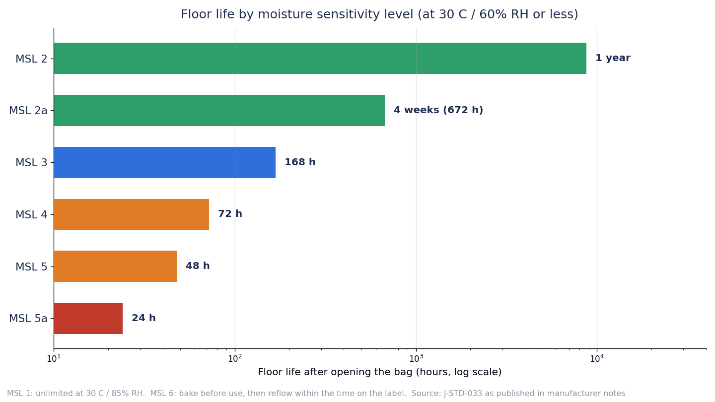
According to materials published by component manufacturers (transcriptions of the table in J-STD-033 Rev D; the values are the same in the MPS, TI and Broadcom materials), floor life is as follows.
| MSL | Floor life | Factory environment conditions |
|---|---|---|
| 1 | Unlimited | 30°C or below, 85%RH or below |
| 2 | 1 year | 30°C or below, 60%RH or below |
| 2a | 4 weeks (672 hours) | 30°C or below, 60%RH or below |
| 3 | 168 hours | 30°C or below, 60%RH or below |
| 4 | 72 hours | 30°C or below, 60%RH or below |
| 5 | 48 hours | 30°C or below, 60%RH or below |
| 5a | 24 hours | 30°C or below, 60%RH or below |
| 6 | Bake before use is mandatory. After baking, reflow within the time stated on the label | 30°C or below, 60%RH or below |
Note that only MSL1 has the condition “30°C/85%RH,” which differs from the “60%RH” of the other levels. If this difference is mixed up when building the system master, MSL1 components may get an unnecessary clock, or conversely the conditions for MSL2 and above may be set too loosely.
The 168 hours of MSL3 is 7 days, and the 72 hours of MSL4 is 3 days. In a plant running 3 shifts, an MSL3 reel reaches its limit 1 week after opening, and an MSL5a reel reaches it in 1 day. The numbers may look generous, but considering that reels go back and forth between the line and the warehouse many times and that time accumulates on each trip, keeping accurate track by hand is not easy.
Correction when the plant differs from 30°C/60%RH (derating)
The floor life values assume “30°C or below and 60%RH or below.” According to TI’s material, moisture absorption is proportional to temperature and humidity, so floor life can be longer in environments below these conditions and shorter in environments above them. J-STD-033 contains a table giving guidelines for equivalent floor life at each temperature and humidity, and TI’s material explains that this table in J-STD-033C gives guidelines by package type and thickness over a range of 20-35°C and 5-95%RH.
Melexis’s material includes an excerpt of equivalent floor life for MSL3 components less than 2.1 mm thick. According to it, the floor life is 7 days at 30°C/60%RH (168 hours, the same as the table above), and the equivalent floor life gets shorter as humidity rises. This article does not transcribe the specific values for conditions above 60%RH; check them in the original J-STD-033 derating table and the component manufacturer’s materials. A 2002 IPC APEX paper states that for thin MSL3 components less than 2.1 mm thick, floor life becomes unlimited below 40%RH.
What this tells us is that reels kept in humid places may reach their limit sooner than the time in the table. Conversely, if records can show that the environment was sufficiently dry, there may be cases where baking is not needed. However, the values in the correction table vary with package type and thickness, and they have not been checked against the table in the original standard for this article. If you build correction into the system, the quality assurance department should decide which value from which table to use, and approve it together with the component manufacturer’s instructions.
Note also that while Melexis states that below 40%RH floor life is unlimited even for MSL3, it recommends a minimum of 40%RH for the working environment because very low humidity makes static electricity more likely (this is a recommendation from the component manufacturer, not a requirement of the standard). A practical approach is to do the drying only inside dry storage and to manage the line environment separately. How to measure temperature and humidity on the line is covered in detail in temperature and humidity monitoring for Thai plants.
Dry Packs, HICs and Shelf Life: What to Check at Receiving
What is inside a dry pack
MSL2-5a components arrive sealed in a moisture barrier bag (MBB) with desiccant and a humidity indicator card (HIC) (for MSL6, pre-drying, the MBB and desiccant are optional, while the labels are mandatory). In the component manufacturers’ materials (the J-STD-033 table transcribed by MPS and Broadcom), MSL2 requires an MBB (with HIC), desiccant, an MSID label and a caution label, and for MSL2a-5a everything, including pre-drying, is mandatory. For MSL1 everything is optional, and no MSID label is needed (however, the caution label is not needed for components classified at 220-225°C, but is needed for components classified at other temperatures).
According to a summary of J-STD-033C compiled by a dehumidifier vendor, a dry pack keeps the inside of the bag below 10%RH at 25°C and provides a shelf life of at least 12 months from the seal date. The HIC has at least 3 spots, at 5%, 10% and 60%RH. In J-STD-033B, the HIC spots changed from the earlier 5, 10 and 15% to 5, 10 and 60%RH.
What to look at during receiving and opening
According to Broadcom’s material, the minimum calculated shelf life is 12 months from the MBB seal date (when stored below 40°C/90%RH), and even beyond 12 months, the components may be reflowed according to their original MSL if the HIC shows that baking is not required. Melexis (for MSL3 products) states that if the HIC is blue at opening (below 10%RH inside the bag), the components may be mounted as they are, and if it is pink (above 10%RH), they should be baked under the conditions on the label before mounting.
Items worth recording at receiving and opening include the following.
- The MSL on the MSID label and caution label, and the bag seal date
- Whether the bag has holes or tears, and whether the heat seal is sound
- Whether the HIC and desiccant are present, and the HIC reading at opening (which spots have changed color)
- The time of opening and the operator
Vendor articles explain that an MBB must be heat-sealed, and that folding it over and taping it gives almost no moisture protection. When returning a partly used reel, “just putting it in a bag and taping it shut” counts as dry storage on paper, but in reality the clock is still running. Broadcom’s material states that the supplied desiccant may be reused if the cumulative exposure is within 30 minutes. If you reuse desiccant, that exposure also needs to be counted.
There are two kinds of shelf life
Two kinds of “shelf life” are easy to confuse. One is the minimum shelf life of a dry pack under J-STD-033, which is 12 months from the seal date. The other is the warranty period for solderability and the like that each component manufacturer specifies individually; for example, MPS gives 5 years from the manufacturing date code for analog ICs, and Melexis gives 4 years from the assembly date code for solderability. When handling long-term stock, we recommend holding these separately in the system as well, so that it is clear which limit is being discussed.
Stopping and Resetting the Clock: Dry Storage Rules
The basic idea
When a partly used reel is returned to a dry cabinet, how should the exposure clock be treated? This is where MSD control is most often misunderstood. Reading the table from J-STD-033 Rev D transcribed by the component manufacturer MPS in a 2024 document (floor life reset and pause at the user side), the rules differ greatly depending on the MSL.
| Applicable MSL | Situation (except for the first row, exposure in an environment of 30°C or below and 60%RH or below) | Treatment |
|---|---|---|
| 2/2a/3/4/5/5a | Placed in an environment of 40°C/85%RH or below (regardless of time) | Reset floor life by baking. If dry-packed after baking, shelf life is also reset |
| 2/2a/3/4/5/5a | Floor life has been exceeded | Reset by baking |
| 2/2a/3 | Exposure exceeded 12 hours | Reset by baking |
| 2/2a/3 | Exposure of 12 hours or less | Reset by placing in dry storage at 10%RH or below for 5 times the exposure time |
| 2/2a/3 | Cumulative exposure is less than floor life | The clock can be paused while kept at 10%RH or below |
| 4/5/5a | Exposure exceeded 8 hours | Reset by baking |
| 4/5/5a | Exposure of 8 hours or less | Reset by placing in dry storage at 5%RH or below for 10 times the exposure time |
Here are some calculation examples. If an MSL3 reel was exposed for 8 hours, 8 hours is 12 hours or less, so it can be reset by placing it in dry storage at 10%RH or below for 8 x 5 = 40 hours. If an MSL4 reel was exposed for 6 hours, 6 hours is 8 hours or less, so it can be reset by placing it in dry storage at 5%RH or below for 6 x 10 = 60 hours. If an MSL4 reel was exposed for 10 hours, it exceeds 8 hours, so it cannot be reset in dry storage and baking is required.
The important point is that in this table, “pause” is written only for MSL2/2a/3. For MSL4/5/5a, there is no row for pausing at 10%RH or below; there is only a conditional reset: “if exposure is 8 hours or less, reset by placing at 5%RH or below for 10 times the time.” An operation that says “once it is in the dry cabinet, the clock stops for any MSL” does not match this table.
Why MSL4-5a cannot be handled simply
Why are highly sensitive components treated so strictly? A paper by researchers at Lucent Technologies (no year is given, but judging from the standards it cites, it appears to be from around 2000) offers a clue. In a model calculation in which an MSL5 PLCC was exposed to 30°C/60%RH for 16 hours and then stored at 30°C/nearly 0%RH, the moisture that had entered near the surface continued to diffuse inward even during storage; about 70 hours after storage began, the moisture concentration at the die surface exceeded the critical value for MSL5, and it did not fall below the critical value until a total of about 210 hours of storage. In a case with 48 hours of exposure, the paper states that the risk of failure was high if reflowed between 35 and 285 hours of storage, and that it took about 640 hours to fall below the critical value.
This is the result of a single analysis case and should not be treated as an industry average or as the basis of the standard. Even so, it is useful material for explaining to the shop floor that “a part does not become safe the moment it is put into a dry cabinet.”
The rules differ by edition of the standard
The rules also differ by edition. A 2002 IPC APEX paper states that if the standard of the time is followed strictly, the exposure clock does not stop even when a part that has once been exposed is returned to dry storage. The short-exposure rule in that paper was “if exposure is 8 hours or less, reset by dry storage for 5 times that time.” The current Rev D (as transcribed by MPS) separates MSL2/2a/3 at 12 hours or less and MSL4/5/5a at 8 hours or less, and allows pausing for MSL2/2a/3.
So when choosing an MSD management system, you need to check “which edition of J-STD-033 the rule engine follows.” Some of the publicly available product materials still refer to older editions, J-STD-033A or J-STD-033B.
Materials describe dry storage humidity differently
Another point to watch is that the humidity conditions for dry storage are described differently in different materials. In MPS’s Rev D transcription, pausing and resetting for MSL2/2a/3 is at 10%RH or below, and resetting for MSL4/5/5a is at 5%RH or below. Broadcom’s material for LED products says that partly used reels should be stored in an MBB resealed with desiccant or in a dry cabinet below 5%RH, and states that this allows pausing but not resetting (the flowchart in the same material also mentions pausing below 10%RH after the first reflow). Some vendor articles state that the clock can be paused below 10%RH, or below 5%RH in a nitrogen atmosphere.
In practice, it is safe to think of it as “dry cabinets at 10%RH or below as the basis, and 5%RH or below if you handle MSL4-5a.” Which value to use should be decided by the component manufacturer’s instructions and your own procedures. It is then important to hold the chosen value as a system setting and keep approval records for any changes.
Baking: Conditions and MSL Component Baking Records
Bake time depends on thickness and MSL
Components that have exceeded their floor life or been outside the conditions are reset by baking (drying by heating). According to the table from J-STD-033 Rev D transcribed by MPS in a 2024 document (bake conditions at the user side; after baking, floor life is counted again from zero), there are 3 bake temperatures, 125°C, 90°C (5%RH or below) and 40°C (5%RH or below), and each is divided into “when the floor life has been exceeded by more than 72 hours” and “when by 72 hours or less.”
Representative values are as follows (when the floor life has been exceeded by more than 72 hours).
| Package thickness and MSL | 125°C | 90°C | 40°C |
|---|---|---|---|
| Over 0.8 mm up to 1.4 mm, MSL3 | 8 hours | 25 hours | 8 days |
| Over 1.4 mm up to 2.0 mm, MSL3 | 27 hours | (omitted in this article) | 37 days |
| Over 2.0 mm up to 4.5 mm, all MSLs | 48 hours | 10 days | 79 days |
Even for over 0.8 mm up to 1.4 mm, if the excess is 72 hours or less, the times are 6 hours at 125°C, 20 hours at 90°C and 7 days at 40°C. For the same thickness, the time increases as the MSL goes up; at 125°C, it is 9 hours for MSL4, 10 hours for MSL5 and 11 hours for MSL5a. BGAs larger than 17 mm x 17 mm and stacked-die packages are given 96 hours at 125°C.
Baking a thick package at 40°C can take more than 2 months. The feeling that “a few days at 40°C on tape and reel will make anything fine” does not match this table.
The notes to the table state, among other things, that the table is based on worst-case lead-frame molded packages, that bake times may be shortened where there is technical justification such as moisture absorption and desorption data, that components exposed to environments above 60%RH may need longer bake times, and that for packages thicker than 4.5 mm the annex of the standard should be referred to.
Heat resistance of packing materials
TI’s material states that devices in tape and reel, trays or tubes must not be baked above 40°C. For trays, it also explains that heat-resistant trays can be baked at 125°C but low-temperature trays only up to 40°C, and Melexis also writes that the maximum bake temperature is marked on trays. There are also conditions specific to individual component manufacturers. For example, Melexis states that for reels of its own MSL3 products, baking at a maximum of 50°C for 48 hours in a low-humidity environment below 1%RH is acceptable (as stated on the MSL label), and that if baking at 125°C, the parts should be removed from the tape and moved to a heat-resistant carrier. This condition applies only to Melexis products and cannot be generalized.
In other words, the bake temperature is determined not only by “the component’s MSL and thickness” but also by “the heat resistance of the packing material” and “the component manufacturer’s specific instructions.” The system master also needs to hold the thickness, packing form and manufacturer instructions for each part number.
Baking also has side effects
Baking is not a cure-all. Rowland (2000) points out that baking can oxidize leads or cause excessive growth of intermetallic compounds, which can reduce solderability, and that components must not be stored in an oven at bake temperature. The 2002 IPC APEX paper stated that under the standard of the time, each component could be baked only once. What limits the current Rev D places on the number of bakes or the cumulative bake time could not be confirmed this time. Confirm the upper limit on the number of bakes with the component manufacturer.
In any case, the system needs to keep a record of “how many times and for how many hours this component has been baked.” We recommend that bake records hold at least the following items.
- The ID and lot of the component (reel or tray), part number, MSL and thickness
- Oven ID, set temperature, start and end times, and record of the actual temperature
- Reason for baking (floor life exceeded, HIC color change, placed in an environment outside the conditions, etc.)
- The number of bakes so far and the cumulative time
- The person who carried it out and the approver
Reflow does not turn the clock back
Broadcom’s material states that floor life is not reset by reflow or rework. Where there are multiple high-temperature processes, as in double-sided assembly or rework, check before the last process that no component has exceeded its floor life. TI also states that for products of MSL2 and above, floor life needs to be considered even after the first reflow, and that because moisture enters while assembled boards are stored, a board bake may be required before additional soldering or rework. This means there are situations where you need not only a “reel clock” but also a “board clock.”
3 Reasons Why MSD Control Does Not Take Hold
With the rules so far in mind, let us look in a little more detail at the 3 reasons given at the start.
Reason (1): The clock is handwritten and breaks along the way
Handwriting the opening time on a label works up to the first opening. The problem comes afterwards. A partly used reel is returned from the line to the warehouse, issued to another line the next day, or put in a cabinet overnight. Each time, someone has to add “what time it went out and what time it came back” and add up the totals. If even one entry is missed at a shift change or by a helper, the cumulative exposure of that reel becomes unknown. Reels whose status is unknown are either sent for “baking just in case” to be on the safe side, or, when things are busy, quietly ignored.
Reason (2): The reset and pause rules are applied uniformly
As we saw in the previous section, the conditions for pausing and resetting in dry storage are different for MSL2/2a/3 and MSL4/5/5a. If the shop floor procedure says only “once it is in the dry cabinet, the clock stops,” a pause that is not in the table ends up being applied to components of MSL4 and above. Conversely, there are probably also plants where unnecessary bakes are increasing because they are not using the pause or the 5x rule allowed for MSL3.
Reason (3): Cabinet humidity is not recorded
The clock can be stopped or reset only while dry storage maintains the required humidity. If a door is left open, a gasket has deteriorated, the dehumidifying unit fails or there is a power cut, conditions are not met during that time. If humidity is not recorded, that time is also treated as “stopped.” If an auditor asks, “What are the cabinet humidity records for this period?”, you cannot answer.
Events That Drive the Clock and Where to Scan
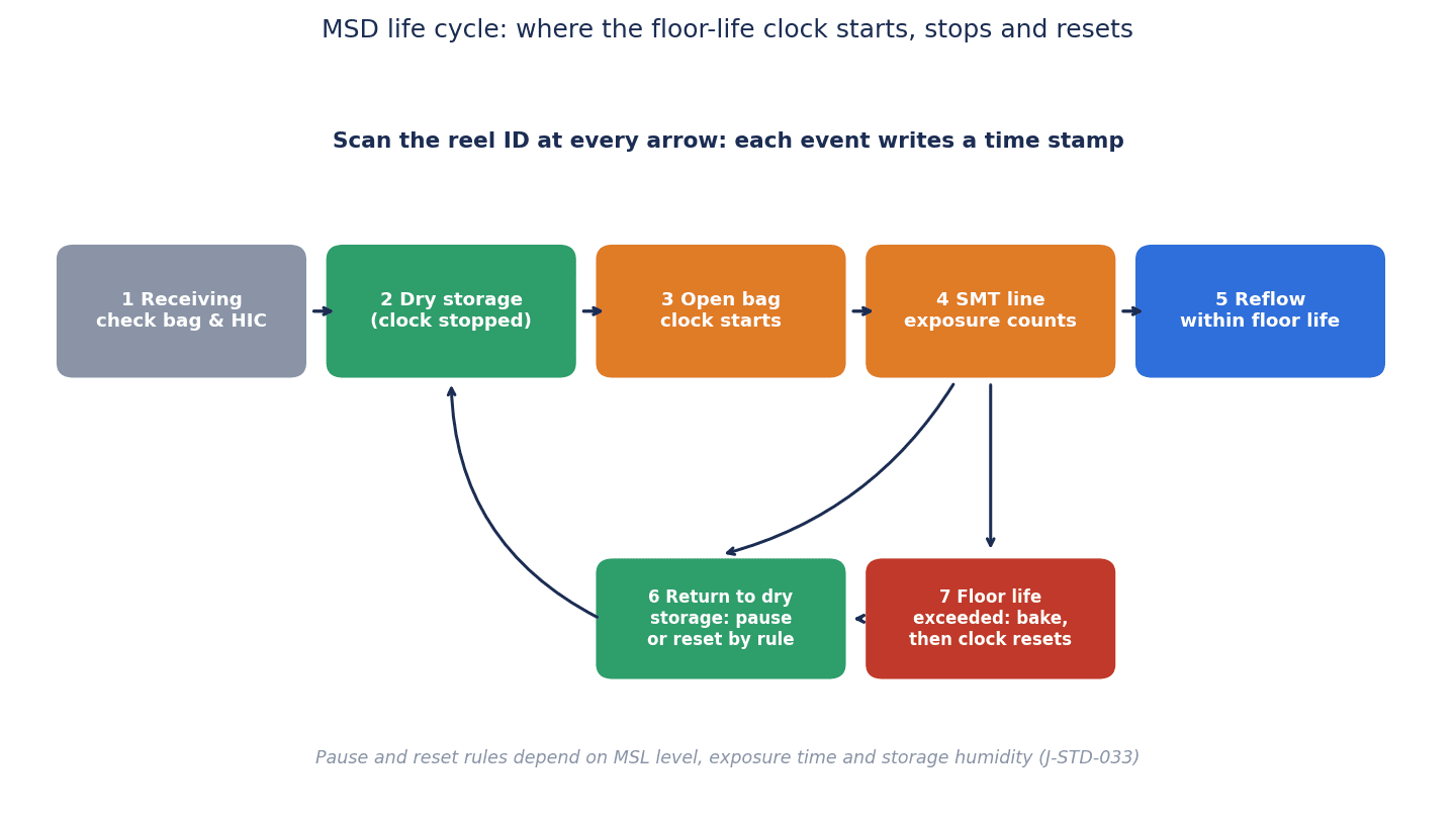
Events drive the clock
The exposure clock moves on “events” that change the state of a reel. As shown in the figure, the main events are receiving, entry into dry storage, opening, issue to the line, loading onto the placement machine, reflow, return from the line to dry storage, floor life exceeded, and bake start and end. If each event records “which reel, when, where, and in what state,” the system can calculate the remaining floor life according to the rules.
| Event | Clock treatment | Main items to record |
|---|---|---|
| Receiving and storage still in dry pack | Does not run (shelf life is managed) | Reel ID, part number, MSL, seal date, bag condition |
| Opening (removal from MBB) | Starts | Opening time, HIC reading, operator |
| Entry into dry storage | Depending on MSL and rules, pause or timing toward reset | Entry time, cabinet ID, cumulative exposure at that point |
| Removal from dry storage | Resumes | Removal time, destination (line or location) |
| Loading onto and unloading from the placement machine | Keeps running | Loading and unloading times, line and machine ID |
| Floor life exceeded | Changes to unusable | Time exceeded, quarantine location |
| Bake start and end | Reset at end | Oven ID, conditions, times, number of bakes |
Reel IDs and scan points
The precondition for reliably capturing events is that each reel or tray has a unique ID. The component manufacturer’s reel label alone may not distinguish between reels of the same part number and the same lot. One possible approach is to attach your own unique ID label at receiving and track by that ID from then on. Issuing IDs and creating labels is covered in label printing systems, and choosing between barcodes, QR codes and RFID in barcode selection for traceability. If a label cannot be read, the clock breaks, so print quality also needs to be checked (introducing a barcode verifier).
Scan points are placed where events happen: the opening bench, in front of the cabinet doors, the component staging area on the line, the setup area for the placement machines, and in front of the bake ovens. As a way of noticing forgotten scans, consistency checks against preceding and following events, such as “warn if a reel with no cabinet entry scan is loaded onto a placement machine,” help you find breaks early.
Align the clocks
The exposure clock is calculated from time differences, so if the clocks of the scanners, terminals, cabinet loggers, placement machines and servers drift, the calculation drifts too. Against the 24 hours of MSL5a, a drift of several tens of minutes cannot be ignored. The approach explained in time synchronization in factories applies directly to deciding which reference to set each device’s time to.
Comparing Moisture Sensitive Device Control Methods: From Paper Labels to MES and Placement Machine Integration
5 methods
MSD control methods can be broadly divided into 5. None of them is the single right answer; the choice depends on the number of part numbers, the MSL distribution, the number of lines and customer requirements.
| Method | Clock accuracy | Humidity records | Prevention of loading | Main fit |
|---|---|---|---|---|
| Paper labels (handwritten) | Depends on what people write. Breaks easily as trips increase | Separate. Usually visual only | Not possible | Works if part numbers are few and mostly below MSL3 |
| Excel or shared sheet | Delays and gaps in transcription. Formulas can be built | Separate | Not possible | Records are easy to search, but not real time |
| MSD management software + existing cabinets | Recorded by scanning and calculated automatically by rules | Linked by adding loggers | Possible if linked with placement machines and MES | Easy to make use of existing equipment |
| Smart tower (automated storage) + software | Entries and removals recorded automatically | Some products hold in-cabinet records | Possible through integration | Plants where storage capacity, picking labor and high-mix changeovers are issues |
| MES and placement machine integration | Recorded automatically down to loading and unloading | Linked with MES and loggers | Can be stopped by interlock | Multiple lines, customers with strict audit requirements |
Examples of published functions
The following are examples of functions written in materials published by each company. All are manufacturer descriptions and do not guarantee effects or compliance. Prices are not published, so they are not covered here.
- Critical Manufacturing MES: According to the manufacturer, “start floor life counter,” “stop,” “reset” and “seal material” can be operated from the material details, process and equipment screens, and the expiry is calculated from the date and time the MSD was opened. The SMT template has a “floor life propagation” function that carries the remaining floor life and expiry from reels to boards and panels, keeping the strictest values (the shortest remaining time and the earliest expiry date).
- Aegis FactoryLogix: According to the manufacturer, opening, consumption, closing and transfer to a bake oven are managed per unique ID, and baking resets the floor life clock. Material that exceeds its MSD clock while loaded changes status automatically and cannot be consumed until it is replaced.
- Siemens (Valor Material Management): A 2020 blog post explains that many material towers have environmental control functions for MSDs, and that the towers and Valor Material Management work together to manage inventory.
- Mycronic MYTower: The 2025 brochure states that an optional dry air unit can bring the inside below 5%RH, that the internal temperature and humidity are recorded as traceability data, and that MSD exposure time is monitored. However, this brochure refers to the older J-STD-033B.
- Neotel SMD BOX: A vendor article states that the inside is always kept below 5%RH, that the clock is stopped while reels are inside, that reels with the shortest remaining floor life are issued first, and that entry, removal and exposure events are recorded with timestamps.
- Inovaxe SMART IMSD2000: A 2022 announcement states that it has built-in MSD tracking and timing software and connects to placement machines and MES. It says that MSD level designations follow the older J-STD-033A.
- Super Dry (Totech): Articles from 2017-2018 claim that floor life can be reset with an ultra-low humidity environment and mild temperatures. Where this method falls within the tables of the standard could not be confirmed from the vendor’s materials.
As for storage capacity, vendor nominal figures have been published, such as up to 1,988 reels (8 mm reels) for the MYTower Series X, up to 640 reels in the 7-inch configuration for the Inovaxe IMSD2000, and 546 reels or 294 trays for the Essemtec Tower (2010). Treat these only as a reference for the order of magnitude.
What this comparison shows is that the function of “counting the clock correctly” lies on the software side, and the tower is just one of its inputs. Even with a tower, if the loading, unloading and return events on the line are not captured, the clock still breaks.
Data exchange standards: IPC-CFX and IPC-1782
There are also standards for exchanging MSD events between equipment and systems. The IPC-CFX (IPC-2591) SDK has a group of messages dedicated to MSD management, defining opening (MaterialsOpened), entry into dry storage (MaterialsPlacedInDryStorage), removal (MaterialsRemovedFromDryStorage), expiry (MaterialsExpired) and return to usable status after reconditioning (MaterialsRestored). The example of the opening message includes items such as unique ID, manufacturer part number, quantity, expiry date and time, first and last exposure date and time, remaining exposure time, MSD level and MSD state. The latest edition of IPC-2591 is Ver 2.0 from 2025.
IPC-1782 (latest is Rev B, 2023) is a standard that defines levels of manufacturing traceability. In an explanatory paper written when IPC-1782 was being developed, material data includes items such as “MSD classification,” and “remaining exposure time for each MSD component” is given as an example of data specific to the SMT placement process. At which level this becomes mandatory was not confirmed this time. In an RFP, “whether MSD events can be exchanged by CFX between cabinets, towers and MES” can be made a check item.
Dry Cabinet Monitoring: Humidity Records and Alarms
From “looking at the display” to “keeping records”
Dry cabinet humidity is the basis for stopping or resetting the clock. Since it is the basis, it needs to be kept as a record. According to vendor articles, typical dry cabinets maintain below 5-10%RH using desiccant, Peltier cooling, membrane separation and similar methods, and a single unit holds about 50-500 reels. However, a standalone cabinet has no tracking function. If you make use of existing cabinets, one possible configuration is to attach a humidity logger to each cabinet and collect the records on a server. The design and cost of plant-wide temperature and humidity monitoring are covered in temperature humidity monitoring system cost and payback.
Humidity sensors need calibration. An example of a vendor’s audit preparation checklist also lists calibration of dry storage equipment and humidity logs (continuous recording is preferable), as well as calibration records for bake ovens.
Recovery after the door is opened
When the door is opened, the humidity inside rises. Vendor articles explain that a good cabinet returns below 10%RH in 5-15 minutes, and that if the door is left open for a long time, it takes 15-30 minutes to return to the target humidity. These are values stated by vendors; the actual recovery time varies with the cabinet, the humidity where it is installed, how long the door was open and the amount of reels inside. Check this in acceptance testing by opening and closing your own cabinets in your own environment.
As a system setting, the basic approach is to treat “time when the humidity exceeds the set value” as time when the clock is not stopped (it runs). For example, while the humidity is above 10%RH, pausing for MSL2/2a/3 is not allowed, and while it is above 5%RH, the time is not counted toward the storage time (10 times the exposure time) required to reset MSL4/5/5a. Alarms are raised when the upper humidity limit is exceeded, when a door stays open for a certain time, and when communication with a logger is lost.
When data is missing, lean toward “not stopped”
Humidity data can be missing because of a dead logger battery, a communication failure or a server outage. The humidity during the missing time is unknown. If unknown time is treated as “stopped,” the records may look safe, but nobody knows whether it was actually safe. In MSD control, we recommend a design that treats missing time as time when “the clock was running.” On top of that, record the fact that data was missing, so that quality assurance can check the affected reels. How to detect and handle missing data is explained in detail in preventing factory sensor data loss. For plants with cleanrooms, there is also the option of putting it on the same platform as cleanroom environmental monitoring.
Integration with Placement Machines, MES and WMS: Keeping Expired Reels off the Line
Records alone do not stop incidents
Even if the exposure clock is counted correctly, it means nothing if a reel past its limit ends up on a placement machine. Integration with placement machines, MES and WMS is what turns a recording system into a “stopping system.” For plants that already have a system to verify feeder and reel IDs at setup (to prevent component mix-ups), the shortest route is to add the MSD state to that verification. At the time of verification, the system judges “expired,” “awaiting bake” or “little time remaining,” and if the reel has expired, loading is not accepted.
Some reels also reach their limit while loaded. As in the FactoryLogix example introduced earlier, the system needs to change the status automatically when the clock is exceeded during loading and prevent consumption until the reel is replaced. Communication methods with equipment include the placement machine manufacturer’s interface, IPC-CFX and, for plants closer to semiconductors, SECS/GEM (SECS/GEM implementation).
Approve and record exceptions
Exceptions will always occur on the shop floor. Examples are “I want to finish just this board with a reel that has 30 minutes left,” or “the component manufacturer has issued a specific instruction that floor life for this part number can be treated as longer.” If the system allows no exceptions at all, the shop floor will start operating outside the system. When exceptions are allowed, you need to record who allowed what, on what basis, for which reel, and design authority so that, for example, approvers are limited to quality assurance. What matters is being able to explain it in an audit afterwards.
The board clock and checks before shipment
In plants with double-sided assembly or rework, the reel clock needs to be carried over to the board. This is the idea, as in the Critical Manufacturing floor life propagation introduced earlier, of giving the board the strictest remaining time of the components built into it. Integration with production management is explained in production management systems for electronics and EMS plants, and the basics of lot linking in how to choose a lot management system. If there is ever a suspicion that expired components have been mounted, the approach of tracing back which boards they were placed on and stopping them before shipment is the same as in preventing defect outflow.
Model Calculation of Costs and Benefits (Hypothetical Figures)
All the figures from here on are hypothetical figures prepared for this article. They are not values from an actual plant, nor industry averages. Read them as an example of the way of thinking and replace them with your own values.
Model assumptions
The assumed plant is a high-mix EMS with 4 SMT lines that handles many MSD part numbers of MSL3 and above. Currently, the opening time is handwritten on the moisture barrier bag and copied into Excel, and dry cabinet humidity is only read by eye from the display. Reels whose cumulative exposure is unknown are sent for “baking just in case.”
The following 2 scenarios are compared.
- Scenario A: Smart tower + MSD management software + MES integration
- Scenario B: MSD management software + labels and scanners + humidity loggers added to existing cabinets
Benefit (1): Fewer bakes
Assume that currently 120 lots a month are baked. By counting exposure time accurately and using resets in line with the rules (such as the 5x rule for MSL3), assume this falls to 50 lots a month. Assume the cost of baking per lot (oven occupancy, electricity and handling) is 300 THB.
- Difference of 70 lots x 300 THB x 12 months = 252,000 THB/year
Because this benefit comes from counting the clock correctly in software, it is assumed to be the same in both Scenario A and B. For reference, the average electricity tariff in Thailand for September-December 2026 is reported as 3.95 baht per kWh (excluding VAT, average unit price), but this differs from the tariff structure for factories, so estimate electricity costs based on your own contract.
Benefit (2): Labor for recording and checking
Assume that currently each of the 3 shifts spends 1.5 hours a day on handwritten records, transcription into Excel and checking remaining time. Labor cost is set at 150 THB per hour.
- 3 shifts x 1.5 hours x 26 days x 12 months = 1,404 hours/year
- 1,404 hours x 150 THB = 210,600 THB/year (Scenario A)
- Scenario B has a narrower scope of automation, so 70% of that = 147,420 THB/year
Replace the labor rate with your actual wages.
Benefit (3): Avoided expected loss from quality incidents
Assume that field failures caused by moisture absorption occur “once every 2 years, at 1,500,000 THB per incident.” The expected loss per year is 750,000 THB. Assuming the management system can prevent 80% of this, the benefit is as follows.
- 750,000 THB x 80% = 600,000 THB/year
This benefit is also assumed to be the same for A and B.
Results for the 2 scenarios
| Item | Scenario A | Scenario B |
|---|---|---|
| Configuration | Smart tower + software + MES integration | Software + labels and scanners + humidity loggers |
| Initial cost | 6,000,000 THB | 1,800,000 THB |
| Annual cost | 450,000 THB | 200,000 THB |
| Benefit (1) fewer bakes | 252,000 THB | 252,000 THB |
| Benefit (2) labor | 210,600 THB | 147,420 THB |
| Benefit (3) avoided quality incidents | 600,000 THB | 600,000 THB |
| Total benefit | 1,062,600 THB | 999,420 THB |
| Net benefit (total benefit – annual cost) | 612,600 THB | 799,420 THB |
| Payback years (initial cost / net benefit) | About 9.8 years | About 2.3 years |
Let us check the arithmetic. For Scenario A, the total benefit is 252,000 + 210,600 + 600,000 = 1,062,600 THB, the net benefit is 1,062,600 – 450,000 = 612,600 THB, and payback is 6,000,000 / 612,600 ≈ 9.8 years. For Scenario B, the total benefit is 252,000 + 147,420 + 600,000 = 999,420 THB, the net benefit is 999,420 – 200,000 = 799,420 THB, and payback is 1,800,000 / 799,420 ≈ 2.3 years.
Sensitivity: assuming no field failures occur
Most of the benefit is (3), avoided quality incidents. So what happens if we assume that field failures would not occur in the first place (benefit (3) set to zero)?
| Item | Scenario A (no field failures) | Scenario B (no field failures) |
|---|---|---|
| Total benefit | 462,600 THB | 399,420 THB |
| Net benefit | 12,600 THB | 199,420 THB |
| Payback years | About 476 years = effectively never pays back | About 9.0 years |
For Scenario A, 252,000 + 210,600 = 462,600 THB minus 450,000 THB gives 12,600 THB, and 6,000,000 / 12,600 ≈ 476 years, so it effectively never pays back. For Scenario B, 252,000 + 147,420 = 399,420 THB minus 200,000 THB gives 199,420 THB, and 1,800,000 / 199,420 ≈ 9.0 years.
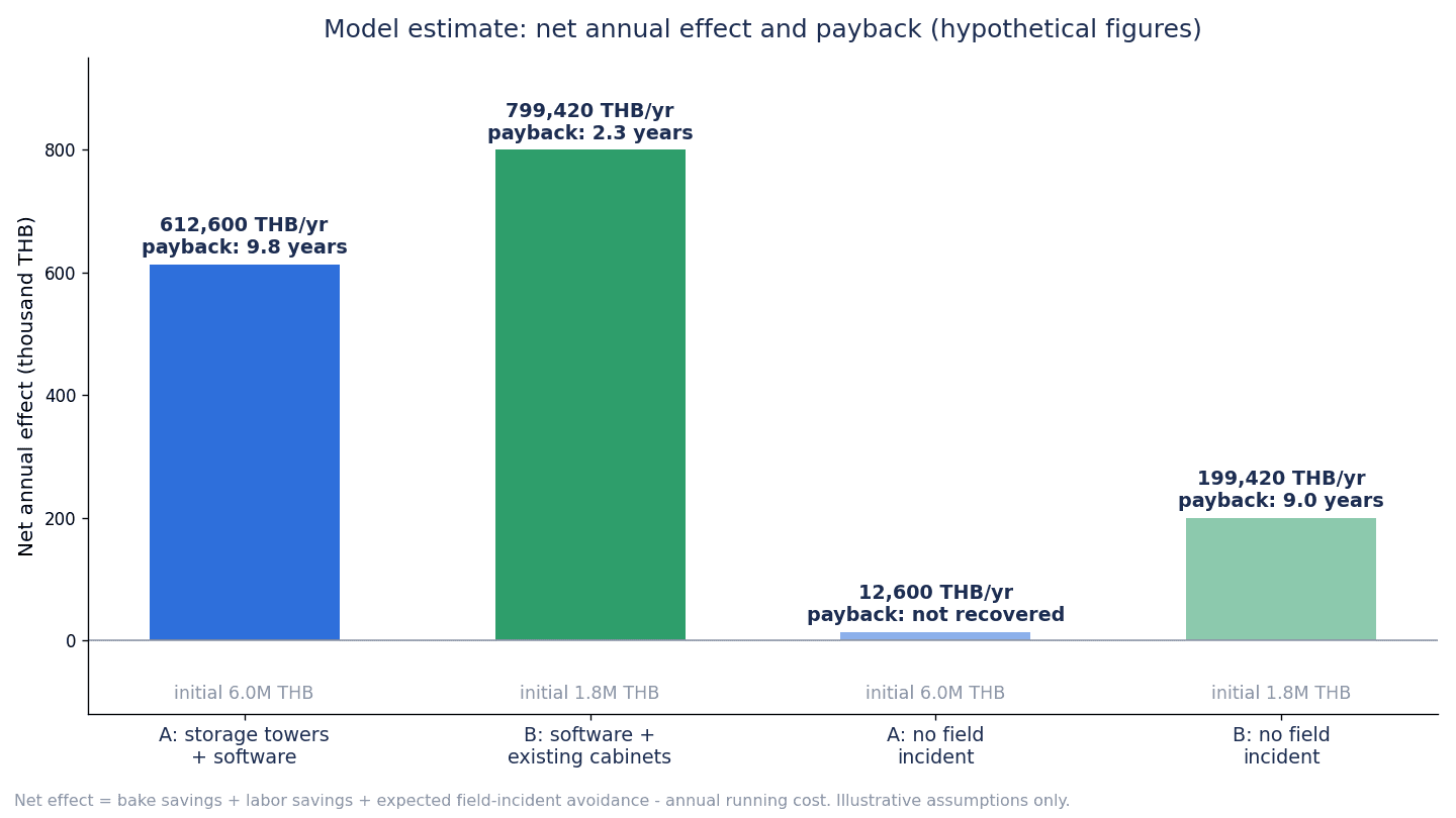
How to read the calculation
There are 3 things this calculation tells us.
First, what determines payback is not the storage equipment but “the accuracy of the exposure clock.” The reductions in baking and labor can be obtained in almost the same amount in A and B just by counting the clock correctly in software.
Second, a storage tower is equipment to be judged on other grounds, such as storage capacity, picking labor and high-mix changeovers. If a tower is installed for MSD control alone, then with these hypothetical figures, A costs 4,200,000 THB more than B initially and 250,000 THB more per year, while the only added benefit is the labor difference of 63,180 THB/year, so the additional investment does not pay back. If you are considering a tower, build up those other benefits using your own values.
Third, most of the benefit comes from avoiding quality incidents, which means it has the character of insurance. If no field failures occur, payback is slow in both scenarios. So it is realistic to judge investment in MSD control not only by “payback years” but also as a response to customer requirements: “can we produce evidence in a customer audit?”
A published case
One of the few published cases is the 2002 IPC APEX paper. It evaluated 1 single-sided SMT line at a Canadian EMS (C-MAC) for about 2 months in 2001, and states that the number of bakes was 13 (average 48 hours) with the manual procedure and 6 (average 19 hours) with the automated system. However, this is an individual case co-authored with the system vendor (Cogiscan), and the estimate was based on the standard of the time (which assumed the clock does not stop in dry storage) and 2001 US dollar unit prices. It cannot be applied directly to plants in Thailand today. Read it as a case showing that “counting the clock accurately tends to reduce bakes.”
What is not included in this calculation
Improvements in placement machine utilization, inventory reduction, tax incentives such as those from the BOI, and the effect of winning new orders are not included. How to look at the cost of the traceability system as a whole is set out in traceability system cost 2026.
What to Check in an RFP and FAT/SAT for J-STD-033 Compliance
Test with your own rules, not catalog functions
Almost every MSD management system tends to be described as “J-STD-033 compliant.” What matters is whether, when your own part numbers and events are run through it under the rules you have decided, it calculates correctly and stops where it should stop. In the RFP (request for proposal) and in the FAT (factory acceptance test) and SAT (site acceptance test), we recommend checking the following items.
| Check item | What to ask in the RFP | How to test in FAT/SAT |
|---|---|---|
| Edition followed | Which edition of J-STD-033 the rule engine follows | Check the differences between editions (the 12-hour and 8-hour split, whether pausing is allowed) with actual data |
| Setting and approval of reset rules | Who can set and change the rules, and whether change history and approvals are kept | Change a setting and check that the history and approver are kept |
| Calculation by MSL | Whether pause and reset can be calculated separately for MSL2/2a/3 and MSL4/5/5a | Run 3 cases: MSL3 exposed 8 hours then stored 40 hours, MSL4 exposed 6 hours then stored 60 hours, and MSL4 exposed 10 hours then stored |
| Derating | Whether it has correction for the factory environment, and who decides which table to use | Compare results with and without correction |
| Missing or excess humidity | How the clock is handled while data is missing or the upper limit is exceeded | Disconnect a logger, leave a door open |
| Time drift | How the times of terminals, equipment and servers are aligned | Deliberately shift a terminal’s time and see whether it is detected |
| Offline operation | Saving scans and sending them later when the network is down | Cut communication, scan, and check whether they are reflected in the correct order after recovery |
| Bake records | Whether temperature, time, number and cumulative totals are recorded and upper limits can be warned | Send the same reel for baking twice |
| Prevention of loading | Whether loading of expired or awaiting-bake reels can be stopped | Put an expired reel on a placement machine |
| Carry-over to boards | Whether boards can hold remaining time in double-sided assembly and rework | Cause an expiry before the second side of double-sided assembly |
| Audit output | Whether the history (opening, storage, humidity, baking) can be listed by reel ID | Assuming an audit, produce the history of an arbitrary reel in a short time |
| Retention period | Retention period of records and archiving method | Check that the design meets the retention period required by customers |
| Multilingual screens | Screens and warning messages in Japanese, Thai and English | Check that operators on the shop floor can understand what the warnings mean |
| Data exchange | IPC-CFX MSD messages and the method of integration with MES and WMS | Check that opening, entry, removal and expiry events arrive |
In acceptance tests, run “abnormal” cases
If you test only normal flows, almost any system will pass. The differences show up in abnormal cases: missed scans, cabinet doors left open, logger communication failures, time drift, loading of expired reels and second bakes. Deliberately cause such abnormalities and check whether the system stops, whether records are kept and whether warnings appear.
How to Introduce It: 90 Days, Starting with 1 Line with Many MSL3-and-above Part Numbers
Rather than introducing it on all lines at once, we recommend trying the exposure clock on 1 line with many part numbers of MSL3 and above, settling the rules and operations, and then expanding.
Days 1-30: Inventory and deciding the rules
- Identify your MSD part numbers and build a master of MSL, thickness, packing form and component manufacturers’ specific instructions
- Count the number of bags opened per month, the number of bakes and their reasons, and the number and condition of dry cabinets
- Measure temperature and humidity in the warehouse, receiving area and lines for several weeks
- Check the pause, reset and bake rules against the component manufacturers’ materials and the original standards, put them into procedures, and have quality assurance approve them
- Decide the 1 target line
Days 31-60: Try the exposure clock on 1 line
- Attach unique IDs to reels on the target line and place scan points at the opening bench, cabinets, line and ovens
- Attach humidity loggers to the target cabinets and collect the records
- Run in parallel with paper records and compare against the remaining time in the system
- Record missed scans and exceptions, and correct the operation
Days 61-90: Integration and acceptance testing
- Add MSD state to the setup verification on the placement machines and stop loading of expired reels
- Run the abnormal cases from the previous section and carry out the SAT
- Assuming an audit, practice producing the history of an arbitrary reel
- Measure changes in the number of bakes and labor, and decide whether to expand to other lines
Points to Check Especially in Thai Plants
Measure temperature and humidity inside the plant
TMD values are outdoor observations. Whether places inside the plant, especially warehouses and receiving areas with weak air conditioning and passages between buildings, exceed 30°C/60%RH cannot be known without measuring. If your operation involves placing reels in locations above the reference, you need to decide how those locations are treated in the clock calculation.
PDPA: recording operator IDs
In an MSD management system, operator IDs remain in the logs of opening, entry and removal, baking and exception approval. Thailand’s Personal Data Protection Act (PDPA, B.E.2562) came fully into force on June 1, 2022. Operators’ names and employee numbers can count as personal data, so one point to consider is stating the purpose (quality traceability), retention period and access rights in the privacy notice for employees. Logging in by fingerprint or facial biometrics can involve sensitive data, so it needs to be considered separately. Confirm the specific response with specialists.
Check the latest conditions for BOI incentives
Under the 2023 guide for the BOI’s “Smart and Sustainable Industry” measure, existing businesses qualify with an investment of 1 million baht or more (land and working capital are not counted in the investment amount), and the adoption of digital technology (1.2) includes items such as introducing software or information systems with 3 or more resource management functions. Whether an investment that integrates MSD control with MES or WMS could qualify is for the BOI to decide. The BOI announced a new set of measures on January 15, 2026, and many of them are said to accept applications from the first business day of 2026 to the last business day of 2027. What is written above is based on the conditions of the 2023 guide, so take the latest announcements and prior confirmation with the BOI as a precondition.
Requirements differ by customer
What each customer requires of MSD control records differs. Automotive customers may require control in line with J-STD-033 through customer-specific requirements (CSR) or audits. List customer requirements such as retention period, record items, handling of exceptions and limits on the number of bakes, and reflect them in the system settings and procedures. Confirm judgments about conformity to standards and customer requirements with your customers and certification bodies.
Multilingual work standards
Procedures for opening, returning and baking assume that operators on the shop floor can understand them in their own language. We recommend preparing Thai work standards, screens and warning messages, and teaching points that are easy to misunderstand, such as “for MSL4/5/5a, there is no provision for pausing even in a dry cabinet (only a conditional reset),” with figures and concrete examples. Training records are also one of the items requested in audits.
Frequently Asked Questions
What is an MSD?
An MSD (Moisture Sensitive Device) is a component that may be damaged by the heat of reflow if it absorbs moisture, which applies to many ICs in plastic packages. The absorbed moisture vaporizes during reflow and causes delamination, internal cracks and, in severe cases, the popcorn phenomenon where the package bursts. A component’s vulnerability is expressed by its MSL (Moisture Sensitivity Level), which the component manufacturer determines according to J-STD-020.
What is the floor life of MSL3?
In materials published by component manufacturers (transcriptions of the table in J-STD-033 Rev D), it is 168 hours (7 days) in an environment of 30°C or below and 60%RH or below. It can be shorter in more humid environments. The specific values need to be checked in the original J-STD-033 derating table and the component manufacturer’s materials. In the end, check the original standard and the component manufacturer’s datasheet and label.
Does the clock stop if I put the reel in a dry cabinet?
It depends on the MSL. In the Rev D table transcribed by MPS, for MSL2/2a/3, if cumulative exposure is less than the floor life, the clock can be paused while the reel is kept at 10%RH or below. If exposure is 12 hours or less, it can also be reset by keeping it for 5 times the exposure time. For MSL4/5/5a, there is no row for pausing, and the condition is that if exposure is 8 hours or less, it can be reset by keeping it at 5%RH or below for 10 times the exposure time. Materials describe the humidity to use differently, so decide by the component manufacturer’s instructions and your own procedures.
What are the bake conditions?
They vary with package thickness and MSL, and with the heat resistance of the packing materials. In the Rev D table transcribed by MPS, for MSL3 components over 0.8 mm up to 1.4 mm thick (floor life exceeded by more than 72 hours), it is 8 hours at 125°C, 25 hours at 90°C and 8 days at 40°C. The thicker the package, the longer it takes; over 2.0 mm up to 4.5 mm, it is 79 days at 40°C. It is important not to bake tape and reel and similar packing above 40°C, and to confirm the upper limit on the number of bakes with the component manufacturer.
Does MSD control need a dedicated system?
It does not necessarily require large dedicated equipment. If part numbers are few and mostly below MSL3, paper or Excel may work. However, in plants with many part numbers of MSL3 and above, where reels go back and forth between the line and cabinets many times, a handwritten clock breaks easily. In this article’s hypothetical calculation, software plus humidity loggers added to existing cabinets gave almost the same reductions in baking and labor as a configuration with a tower.
What is the latest edition of J-STD-033?
In IPC’s document revision table, the latest edition of J-STD-033 is Rev D from May 2018. In the revision table it has the status “No Longer Maintained” (a document for which no revision work is currently planned) (checked in October 2026). There is no Rev E. If product materials refer to older editions (Rev A or Rev B), check the differences from the current edition in the RFP.
What are the introduction cost and period?
It varies greatly with the number of part numbers and lines, whether you make use of existing cabinets or install a tower, and how far you integrate with placement machines and MES, and there are no published prices, so it cannot be stated uniformly. In this article’s hypothetical calculation, we assumed an initial 6,000,000 THB and annual 450,000 THB for tower + software + MES integration, and an initial 1,800,000 THB and annual 200,000 THB for software + scanners + humidity loggers. As for the period, we showed as a guide an approach of trying it for 90 days on 1 line with many part numbers of MSL3 and above, and then expanding to other lines.
Summary
- The core of MSD control is not the storage but the exposure clock for each reel. If the time out, the time back and the humidity in between are not stacked on the reel ID, the remaining floor life cannot be known
- Floor life by MSL, at 30°C or below and 60%RH or below, is 168 hours for MSL3, 72 hours for MSL4 and 24 hours for MSL5a (MSL1 is unlimited at 30°C/85%RH). The figures are based on transcriptions of the Rev D table published by component manufacturers; in the end, check the original standard and datasheets
- Pausing in dry storage applies only to MSL2/2a/3. For MSL4/5/5a, the condition is a reset by keeping the reel at 5%RH or below for 10 times the time if exposure is 8 hours or less. Do not apply a uniform rule to all MSLs
- Bake time is determined by thickness, MSL and the heat resistance of the packing materials. Tape and reel should not exceed 40°C. Record the number of bakes and cumulative time, and confirm the upper limit with the component manufacturer
- Record cabinet humidity, and treat periods of missing data or exceeded limits as time when the clock was running
- To keep expired reels from being loaded, add MSD state to the placement machine setup verification, and approve and record exceptions
- In the hypothetical calculation, the software-centered B pays back in about 2.3 years and A, which includes a tower, in about 9.8 years. Assuming no field failures, A effectively never pays back and B takes about 9.0 years. What determines payback is not the storage equipment but the accuracy of the clock
- Most of the benefit comes from avoiding quality incidents, so judge it as a customer requirement: whether you can produce evidence in a customer audit
- In the RFP, check which edition of J-STD-033 the system follows, and in acceptance tests deliberately cause missed scans, open doors, communication failures, time drift, loading of expired reels and second bakes
- In Thailand, check early on measuring temperature and humidity inside the plant, the PDPA treatment of operator IDs, the latest BOI conditions, requirements of each customer and multilingual work standards
TOMAS TECH helps factories in Thailand with collecting data from equipment and sensors, building part identification and traceability systems, and integrating them with existing systems. You can also consult us before choosing a product, for example at the stage of taking inventory of your MSD part numbers and their MSL distribution, or at the stage of trying the exposure clock on 1 line. Please contact us through this form.
References
- IPC: Document Revision Table (editions of J-STD-033, J-STD-020, IPC-1782 and IPC-2591, viewed October 2026)
- MPS: Moisture Sensitivity Technical Note (April 2024)
- Texas Instruments: SLVA840 (January 2017)
- Texas Instruments: SPRABY1A (December 2018)
- Broadcom: AV02-1298EN (June 2020)
- Melexis: Guidelines for Storage and Handling of Plastic Encapsulated ICs (April 2020)
- Eureka Dry Tech: IPC/JEDEC J-STD-033C
- Robert Rowland: Explanation of moisture sensitive components in SMT magazine (October 2000)
- Neotel Technology: IPC/JEDEC J-STD-033 MSD Storage (October 2025)
- Circuitnet: Experts Q&A (first published February 2015, updated June 2026)
- Lucent Technologies: Handling of Highly Moisture Sensitive Components
- IPC APEX 2002: Paper by C-MAC and Cogiscan
- Circuits Assembly: The Moisture Sensitivity Standard Goes Pb-Free (January 2007)
- Circuits Assembly: Latest MSD Spec Rev Covers Non-IC Parts (February 2012)
- CALCE (University of Maryland): Abstract of a study on the popcorn phenomenon in PBGAs (1997)
- Wikipedia: Humidity indicator card
- Critical Manufacturing: Moisture Sensitive Level Overview
- Critical Manufacturing: Support Floor Life Propagation
- Aegis: FactoryLogix Handling Moisture Sensitive Devices
- Siemens: Automated material management for electronic assemblies (November 2020)
- Mycronic: MYTower Brochure (2025 edition)
- Electronic Specifier: Essemtec Tower (August 2010)
- EPP Europe: Storing and drying of moisture sensitive devices (October 2017)
- EMSNow: Super Dry (April 2018)
- Electronics For You: Inovaxe SMART IMSD2000 (December 2022)
- IPC-CFX SDK: MSDManagement Namespace
- IPC-CFX SDK: MaterialsOpened
- IPC: IPC Releases Version 2.0 of IPC-2591 CFX (April 2025)
- IPC: IPC-1782B Table of Contents (2023)
- Mentor Graphics: Explanatory paper on IPC-1782
- BOI: Press Release No.166/2569, national semiconductor and advanced electronics strategy (September 24, 2026)
- BOI: Press Release No.171/2569, Infineon plant opening (October 1, 2026)
- Naewna: Investment promotion approved for ShuCan (Thailand) PCBA plant (September 14, 2026) (in Thai)
- The Nation: BOI investment promotion applications in the first half of 2026 (July 23, 2026)
- The Nation: PCB clustering in Thailand (February 23, 2026)
- TMD: Climatological Data of Thailand for 30 Year Period 1991-2020
- BOI: Smart and Sustainable Industry (Investment Promotion Guide 2023)
- Alvarez & Marsal (Mondaq): Thailand’s Renewed BOI Incentives 2026-2027 (February 2026)
- The Nation: Electricity tariff for September-December 2026 (July 23, 2026)


