


Introduction — Pressure Sensor Selection Does Not Start with “How Many MPa”
The factory’s compressed-air supply pressure drops, and equipment suffers minor stoppages. A suction failure drops a workpiece. A drop in hydraulic clamp pressure is noticed only at inspection in a downstream process. Pressure is only checked by eye on Bourdon tube gauges on the piping, and no records are kept. Each machine has pressure switches from a different manufacturer, with different threads and outputs, and when one fails, nobody knows what to buy. On liquid lines, sensors break, readings drift, and the PLC analog value does not match the pressure gauge. Discussions about pressure sensors usually start from problems like these.
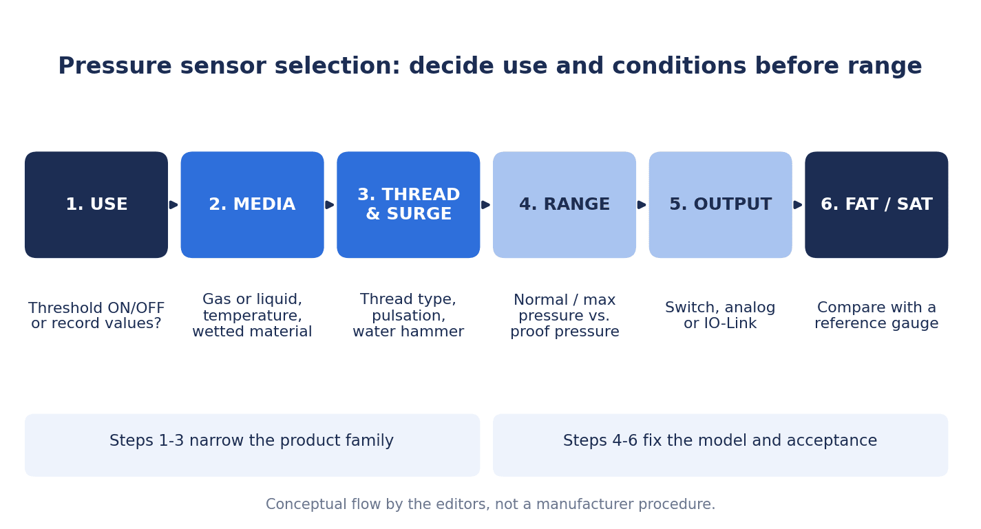
Here is the main point of this article up front. In this article, we take the view that pressure sensor selection is decided by the following two points before “what MPa range the product has”.
- (1) What decision it is used for: switching ON/OFF at a threshold, or recording continuous values to watch trends
- (2) Media, connection and surge conditions: gas or liquid, which thread it is mounted with, and whether there is pulsation or water hammer
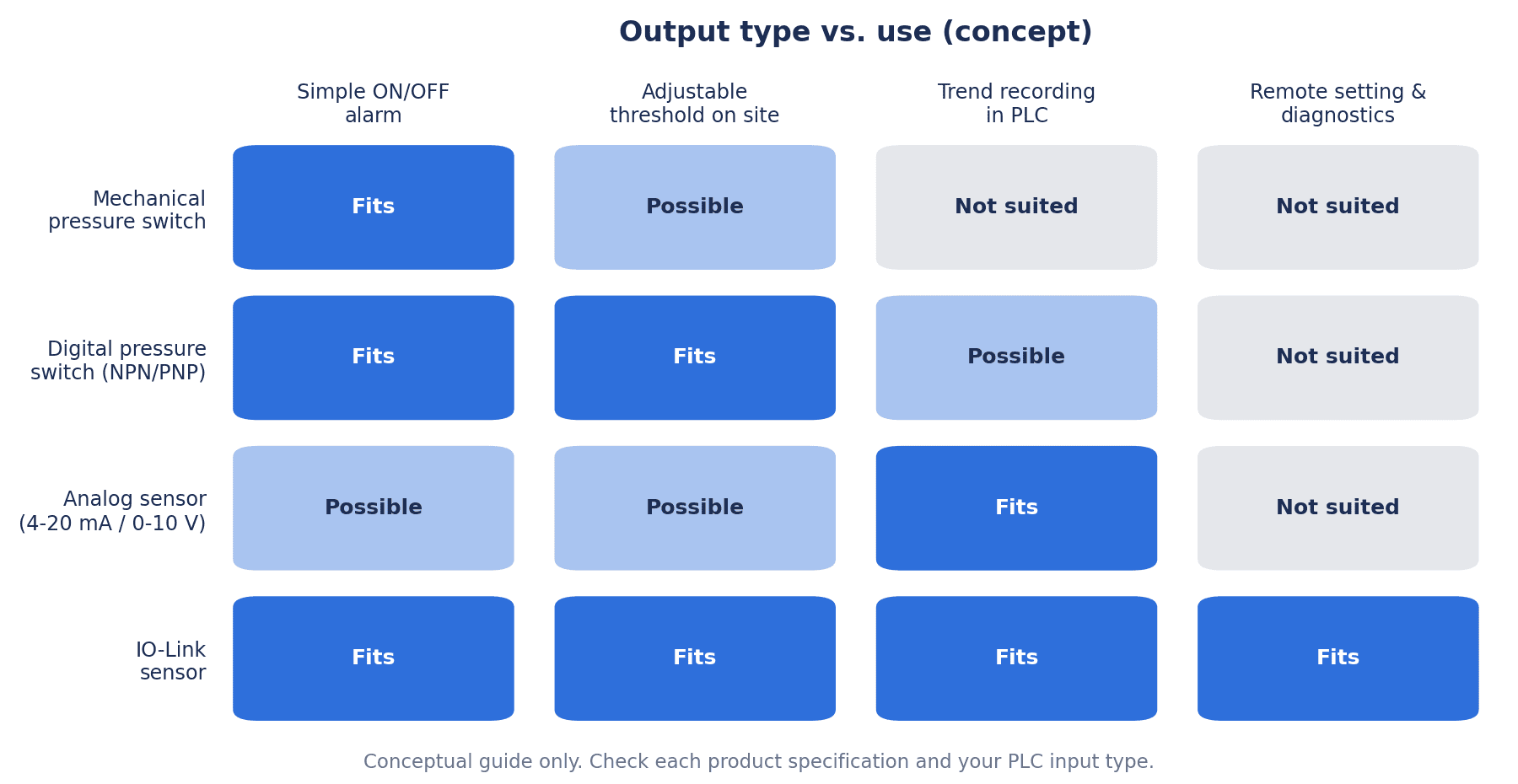
Point (1) determines whether you choose a pressure switch (mechanical or digital pressure switch) or a pressure sensor that outputs values via analog or IO-Link. It also changes how you read accuracy. Point (2) narrows down the usable models even within the same series. The range is decided after that, from the relationship between normal operating pressure, maximum pressure and proof pressure. At acceptance, the displayed value, the output value and the value on the PLC side are compared against a reference pressure gauge, and the threshold and delay settings are recorded.
This article is not a recommendation or ranking of specific products. Manufacturer specifications are based on each company’s published materials and are presented in the form “the company states that…”. The cost estimate in the second half uses hypothetical numbers for this article. Differential pressure monitoring for cleanrooms and dust collectors, flow meters, hydraulic oil condition monitoring, and how to choose vacuum pads and solenoid valves are left to their own articles, and this article links to them where relevant.
Why Thai Factories Are Revisiting Pressure Visibility Now
Investment in automation continues in Thailand. According to the Thailand BOI (Board of Investment), there were 1,299 investment promotion applications in January to June 2026, worth USD 43.6 billion (about THB 1.47 trillion), up 37% year on year. Of these, the machinery, automation and robotics sector accounted for 82 applications worth USD 387.4 million. Applications under the “Smart and Sustainable Industry” measure (machinery upgrades, adoption of digital technology, integration of automation and robotics) numbered 132, worth USD 507.6 million. Investment applications from Japan numbered 123, worth USD 970.1 million. All of these figures are based on applications and differ from approved amounts.
Production figures are mixed. According to a Reuters report, Thailand’s car production in August 2026 was 124,646 units, up 10.93% year on year. On the other hand, the Federation of Thai Industries (FTI) lowered its full-year production outlook from the previous plus 3% to minus 3.33%. The Manufacturing Production Index (MPI) for the same month of August rose 4.44% year on year, with higher electronics production cited among the factors. The S&P Global Thailand Manufacturing PMI was 54.3 in September 2026, up from 53.8 in August and the highest level since December 2025 (according to the aggregator site Trading Economics).
With production volumes moving up and down, efforts to reduce equipment stoppages and defects are a theme that is easy to keep going. Pressure, whether supply pressure, suction, clamping or coolant, is a value that represents the “conditions for normal operation” of many machines. For factories that do not record that value, one option is to start visibility with pressure. However, the statistics above are national figures. For investment decisions at an individual factory, please use your own stoppage and defect records.
Pressure Sensors vs Pressure Switches — Mechanical, Digital Pressure Switches and Pressure Sensors
First, let us sort out the terms. In this article, we divide devices into the following three categories. This is an editorial classification. Product naming is not consistent across companies. For example, SMC uses “digital pressure switch”, while Panasonic and KEYENCE use “digital pressure sensor”.
| Category | Main output | Suitable use |
|---|---|---|
| Mechanical pressure switch | Contact ON/OFF only | Uses where switching at one fixed pressure is enough |
| Digital pressure switch | Display and switching output (many also have analog or IO-Link) | Uses where thresholds are set and judged while viewing values on site |
| Pressure sensor (transmitter) | Continuous values via analog or IO-Link | Uses where values are recorded in a PLC or higher-level system to watch trends |
The WIKA technical blog explains how mechanical pressure switches work as follows. The measuring element is a diaphragm or a piston, with a diaphragm used at low pressure and a piston at high pressure. The switch point is determined by the preload of a spring.
On choosing between mechanical and electronic types, WIKA explains as follows. Mechanical types are often used when the budget is limited and only individual switch points are needed, or for redundancy in safety applications. On the other hand, mechanical wear can lead to signal drift or early failure. Electronic types are chosen when multiple switch points, analog output, a display or changes to settings are needed.
Put in shop-floor terms, it looks like this. A mechanical switch gives only contact ON/OFF, and you cannot tell what the current pressure is. A digital pressure switch lets you see the value on site and set thresholds as numbers. A pressure sensor sends the value itself to the control panel or system. Which one to choose depends on “what you want to judge” and “whether you want to keep the values”.
Types of Pressure Sensors (1) — Gauge, Absolute, Differential and Compound Pressure
When considering the types of pressure sensors, the first thing to check is “what the pressure is referenced to”. NI explains that there are three types of pressure measurement: absolute, gauge and differential.
- Absolute pressure: pressure referenced to a perfect vacuum (WIKA’s explanation)
- Gauge pressure: the difference between absolute pressure and the local atmospheric pressure. WIKA explains that “in most cases, the purpose of measurement is to determine gauge pressure”
- Differential pressure: pressure referenced not to ambient air pressure but to another pressure point in the system (NI’s explanation)
WIKA cites the additional errors when a gauge pressure sensor is used in an application that should measure absolute pressure: ±30 mbar (3 kPa) from weather changes, and up to 200 mbar (20 kPa) from a change in location (such as from 0 m to 2,000 m above sea level). The company explains that this is a large error for pneumatics with a measuring range of 1 bar, while it is almost negligible for hydraulics at 400 bar. Gauge pressure is often sufficient for monitoring factory pneumatics and hydraulics, while in processes that need precise vacuum measurement, this difference starts to matter.
There is also the term “compound pressure”. KEYENCE divides the sensor heads of the AP-V80 series into types such as “compound pressure type”, “negative pressure type” and “positive pressure type”. For example, the compound pressure type AP-10S is rated 100 to −100 kPa, and the negative pressure type AP-11S is 0 to −100 kPa. Panasonic states that for the DP-100, “all models are lined up as compound pressure types”, so there is no need to choose the sensor based on positive or negative pressure. However, in the English specification table for the same product, the pressure type field reads “Gauge pressure”. In other words, compound pressure is used as a term for a range that covers both the positive and negative sides of gauge pressure.
SMC separates them by part number series. In MonotaRO’s listing names, the ISE20 series is for positive pressure, and the ZSE20(F) series is for vacuum and compound pressure.
Some products can monitor differential pressure with a single unit. KEYENCE explains that the AP-V80 differential pressure amplifier attaches two heads to one amplifier to detect the differential pressure between the primary and secondary sides, and can detect differential pressure on output 1 and the primary side (supply pressure) on output 2.
Room-to-room differential pressure in cleanrooms and filter differential pressure in dust collectors follow a different design approach. These are covered in our article on cleanroom differential pressure monitoring, so please refer to it. This article focuses on gauge pressure sensors (positive, negative and compound pressure) mounted on equipment piping.
Types of Pressure Sensors (2) — Sensing Methods
There are also differences in sensing method, that is, how pressure is converted into an electrical signal. NI explains the representative methods as follows.
| Method | Summary of NI’s explanation |
|---|---|
| Bridge-based (strain gauge) | The most common type |
| Foil strain gauge | High-pressure (up to 700 MPa) applications. Operating temperature of 200°C compared with 100°C for silicon strain gauges |
| Silicon strain gauge | High sensitivity, also used in low-pressure (2 kPa or below) applications. Large overload |
| Capacitive | Measures the change in capacitance between a metal diaphragm and a fixed metal plate |
| Piezoelectric | Uses the charge of quartz and needs no external excitation. Susceptible to shock and vibration, suited to fast events |
On the product side, each company explains as follows.
- ifm PN7092: a ceramic-capacitive pressure measuring cell
- Festo SPAN: relative measurement with a piezoresistive measuring cell
- KEYENCE GP-M: a ceramic (alumina) diaphragm with excellent oil resistance. The name of the sensing principle could not be confirmed in the body text of the product page
- Omron E8PC: the page for Thailand contains both a statement that it uses a piezoelectric element and a statement that it detects pressure through the change in resistance of a strain gauge
As this shows, the names of methods are not consistent across companies, and in practice it is difficult to compare products by the method name in the catalog alone. In this article, we take the view that for pressure sensors mounted on equipment, it is more practical to compare by the items covered next, namely media, proof pressure, accuracy and output, rather than by method name. We could not find any primary source this time that generalizes the merits of each method.
The First Decision — Threshold Judgment or Recording Continuous Values
This is where selection really begins. The first thing to decide is what decision the pressure will be used for.
Switching ON/OFF at a threshold
These are uses where ON/OFF is decided by a threshold, such as “stop the equipment if supply pressure drops” or “move to the next operation once suction is achieved”. In this case, a pressure switch with a switching output (NPN/PNP) is enough.
The accuracy to look at here is not limited to measurement accuracy. WIKA explains that “accuracy” and “switch point accuracy” of an electronic pressure switch are different things, and that the switching output logic adds further error. On that basis, the company concludes that switch point accuracy should mainly be used when selecting an electronic pressure switch.
Some datasheets actually list the two as separate items. For the PN7092, ifm lists switch point accuracy as “< ±0.5 % of the span" and characteristic deviation as "< ±0.25 % (BFSL)" separately.
Recording continuous values to watch trends
These are uses where you want to keep the values themselves, such as “we want to know at what times of day supply pressure drops” or “we want to catch signs of clamp pressure gradually declining”. In this case, choose a pressure sensor that can send values to a PLC or higher-level system via analog output (4-20 mA or voltage) or IO-Link. The accuracy to look at is measurement accuracy (linearity, hysteresis, repeatability, temperature characteristics) and the resolution when the value is acquired on the PLC side. How to use the recorded values for equipment maintenance is covered, together with a cost breakdown, in our predictive maintenance system implementation guide.
An example of different initial settings by use case for the same product
Panasonic states that for the DP-100, “the low-pressure type is initially set to the optimum state for suction confirmation, and the high-pressure type for supply pressure confirmation”. This is an example of the manufacturer itself thinking about judgment differently depending on the use case.
Response time is not “the faster the better”
Response time is also considered by use case. Each company’s explanation is as follows.
- KEYENCE GP-M: control output response time selectable from 3 to 5000 ms. For analog output, 2 ms is added to this value (90% response)
- Panasonic DP-100: 10 steps from 2.5 ms to 5,000 ms. The company states that this “prevents chattering and malfunction caused by sudden pressure changes and the like”
- SMC ISE20B: response time 1.5 ms or less
- ifm PN7092: response time < 3 ms. Delay time settable from 0 to 50 s
- Omron E8PC: control output selectable from 3 to 6000 ms
As Panasonic’s explanation indicates, response time is also a function for deliberately setting a slower response to prevent chattering (output flickering). For uses that need speed, such as suction confirmation, and uses where you do not want a momentary dip to stop the equipment, such as supply pressure monitoring, the approach to setting is the opposite. These setting values are among the items to be recorded in acceptance testing.
Media and Wetted Materials — For Gas or for Liquid
The next thing to decide is the media. Even within the same series, there are examples where the usable media differ by model.
For the GP-M series, KEYENCE describes the GP-M001, GP-M010 and GP-M025 as being for “gases and liquids that do not corrode the wetted materials”, and the GP-M100, GP-M250 and GP-M400 as being for “liquids that do not corrode the wetted materials”. If you choose a model by range alone, you could end up choosing a liquid model for a gas line.
Here are each company’s descriptions of compatible media and wetted parts.
| Product | Compatible media (company’s description) | Wetted parts (company’s description) |
|---|---|---|
| KEYENCE GP-M | Gases and liquids, or liquids only, depending on model | Pressure port SUSXM7, diaphragm pressure port alumina, O-ring FKM |
| Omron E8PC | E8PC-010: water, glycol solutions, oil, etc. E8PC-100/400: water, water-soluble coolant, non-water-soluble oil, etc. | Pressure port SUS304, diaphragm pressure port alumina, O-ring FKM |
| ifm PN7092 | Liquids (use with gases is conditional, and the datasheet states that inquiry is required for pressures above 25 bar) | Stainless steel (316L), ceramic, FKM |
| Panasonic DP-100 | Non-corrosive gases | The company states that gas-contact parts are cleaned and assembled on an oil-free line |
| SMC ISE20B | Air, non-corrosive gases, non-flammable gases | Could not be confirmed in published materials |
| SMC ISE20C-X-02-A1 | Liquids and gases that do not corrode SUS630 and SUS304 (specifications listed on an online store) | Could not be confirmed in published materials |
What this table tells us is not to install gas-only products (such as the DP-100 and ISE20B) on coolant, cooling water or hydraulic oil lines. Even pressure switches from the same manufacturer may come in different series for gas and for liquid. When ordering replacement parts, please check the compatible media together with the part number series.
Temperature and condensation also need attention. In a specification note for the GP-M, KEYENCE lists “keep the sensor at least 30 cm away from cold piping using a pressure guide tube” as a measure against condensation. This means that if a sensor is mounted directly on cooling water piping, the sensor body itself may condense. Write this condition into the RFP under “media and temperature”.
Rated Pressure, Proof Pressure, Burst Pressure and How to Decide the Range
Only now do we come to the range. In addition to rated pressure (the range that can be measured), pressure sensor specifications list proof pressure and burst pressure. The English terms are not consistent: Omron writes “Overload pressure”, Panasonic “Pressure withstandability”, and ifm “Pressure rating”. In this article, we call the upper limit of pressure that may be applied per the specification “proof pressure (overload pressure)”, and the value shown as the pressure leading to rupture “burst pressure”, and distinguish between them.
The specification table for the KEYENCE GP-M series is as follows (company’s description; the values are the same for the GP-M□T type and the GP-M□ type).
| Model | Rated pressure range | Proof pressure | Burst pressure |
|---|---|---|---|
| GP-M001(T) | −100 to +100 kPa | 400 kPa | 1.5 MPa |
| GP-M010(T) | −0.1 to +1 MPa | 4 MPa | 15 MPa |
| GP-M025(T) | −0.1 to +2.5 MPa | 10 MPa | 35 MPa |
| GP-M100(T) | 0 to +10 MPa | 30 MPa | 100 MPa |
| GP-M250(T) | 0 to +25 MPa | 50 MPa | 100 MPa |
| GP-M400(T) | 0 to +40 MPa | 50 MPa | 100 MPa |
The specifications for the Omron E8PC are as follows (company’s description).
| Model | Rated pressure range | Proof pressure (Overload) | Burst pressure (Burst) |
|---|---|---|---|
| E8PC-010 | −0.1 to 1 MPa | 4 MPa | 8 MPa |
| E8PC-100 | 0 to 10 MPa | 30 MPa | 60 MPa |
| E8PC-400 | 0 to 40 MPa | 50 MPa | 80 MPa |
In the GP-M table, dividing proof pressure by the upper limit of the rating gives 4 times for the GP-M001, GP-M010 and GP-M025, and the ratio becomes smaller for the higher-pressure models GP-M100, GP-M250 and GP-M400, reaching 1.25 times for the GP-M400. For this series, it can be said that the higher the range, the smaller the proof pressure margin ratio. However, these are values calculated from this series’ table and are not a general rule for pressure sensors.
Let us also look at other companies’ values. Panasonic gives a proof pressure of 500 kPa for the DP-101 (−100.0 to +100.0 kPa) and 1.5 MPa for the DP-102 (−0.100 to +1.000 MPa). For the PN7092 (0 to 10 MPa), ifm lists a Pressure rating of 30 MPa, a minimum bursting pressure of 65 MPa and a minimum of 100 million pressure cycles. WIKA explains that the overload safety factor of a typical sensor is “2 to 4 times”. Looking at each company’s models, the ratio of proof pressure to the upper limit of the rating varies greatly by model.
In a cautionary note in its specifications, Panasonic explains that applying pressure above the proof pressure damages the diaphragm, and correct operation can no longer be maintained.
So how should the range be decided? In this article, we recommend thinking in the following order.
- Write down the normal operating pressure (everyday pressure) and the maximum pressure during operation, from on-site pressure gauges or design values
- Check how large the surge (momentary pressure spike) covered in the next section could be
- Shortlist models in which the normal operating pressure sits at an easy-to-read position within the range, the maximum pressure stays within the rating, and the surge stays within the proof pressure
- If it does not fit, consider whether the surge can be suppressed with a restrictor or snubber before raising the range
A general rule of “choose a range of so many times the rating” was not written in the primary sources we checked this time. Rather than fixing a ratio in advance, please check the relationship between normal operating pressure, maximum pressure, surge and proof pressure for each model.
Countermeasures for Surge, Pulsation and Water Hammer
On liquid lines, sensors can break. WIKA explains that the most common cause of pressure sensors repeatedly failing from excessive pressure on liquid lines is water hammer, which in extreme cases can reach several hundred bar.
In a specification note for the E8PC, Omron requires that momentary pressure fluctuations such as water hammer also be kept within the proof pressure, and that the supplied restrictor (throttle) be used when momentary fluctuations are expected. What matters here is that the judgment is based not on the rated range but on whether the momentary pressure exceeds the proof pressure.
Choosing a product with a larger range as a surge countermeasure has its limits. WIKA gives an example such as using a 300 bar sensor on a 3 bar water supply system and explains that the measurement uncertainty increases accordingly. On that basis, the company lists using a snubber and restricting the pressure channel to less than 1 mm. However, the company also writes that, because of inertia, very fast pressure peaks may not be fully suppressed by a snubber.
WIKA also gives a guide on how fast pressure rises. In a valve opening and closing example, it explains that a pressure rise of about 70% in 30 ms is no problem, while for the company’s sensors, a rise from zero to the upper limit of the nominal pressure should not occur in less than 1 ms. Changes faster than this require measures such as a snubber or a narrow EDM-machined channel, according to the company.
Each company’s product-side measures are as follows.
- Omron E8PC: use the supplied restrictors (E8PC-YS, E8PC-YS-N)
- KEYENCE AP-V80: the high-pressure heads AP-14S to 16S are “with throttle”
- ifm PN7092: no built-in restrictor element, but one can be retrofitted (Restrictor element integrated: no (can be retrofitted))
In this article, we recommend stating in the RFP whether a restrictor or snubber is to be used on hydraulic and water-based piping. Because a general ratio for the size of surges could not be confirmed in primary sources, we do not set any expectation such as “so many times the system pressure”. A realistic approach is to check how much the pressure actually spikes at the timing of valve opening and closing or pump start and stop, by recording peak values during commissioning. Companies describe functions that hold and display peak and bottom values, as in the Panasonic DP-100 and Omron E8PC.
How to Read Accuracy — %F.S., Linearity, Hysteresis and Temperature Characteristics
A comparison table that simply says “accuracy ±1%” needs to be read with care. WIKA explains that the term “accuracy” itself is not defined in any national or international standard, and that in practice it should be looked at through individual items such as non-linearity, hysteresis, non-repeatability and maximum error.
Here are each company’s descriptions.
| Product | Description of accuracy (company’s description) | Repeatability | Temperature characteristics |
|---|---|---|---|
| KEYENCE GP-M | ±1.0% of F.S. or less (value considering linearity, hysteresis and repeatability under a constant 23°C environment) | ±0.3% of F.S. or less | ±0.6% of F.S./10°C |
| Omron E8PC | Pressure monitoring precision ±1.0% of F.S. or less (specified with water at normal temperature) | ±0.3% of F.S. or less | ±0.6% of F.S./10°C (specified by applying pressure at 50% of the maximum rating with oil) |
| Panasonic DP-100 | Linearity of analog output on the high-function type within ±1% F.S. | ±0.1% F.S. (low pressure), ±0.2% F.S. (high pressure) | Within ±0.5% F.S. (low pressure), within ±1% F.S. (high pressure) |
| SMC ISE20B | Could not be confirmed in published materials | ±0.2% F.S. | Could not be confirmed in published materials |
| ifm PN7092 | Switch point accuracy < ±0.5% of the span, characteristic deviation < ±0.25% (BFSL), hysteresis deviation < ±0.25% | < ±0.1% of the span (temperature fluctuation < 10 K) | Temperature coefficient of zero point and span < ±0.2%/10 K |
There are three points to note when reading this.
The first is what has been added together in the value. KEYENCE notes that the GP-M accuracy is a value that takes linearity, hysteresis and repeatability into account. Temperature characteristics are a separate item. In environments where the ambient temperature around the equipment changes, allow for the temperature characteristics separately.
The second is the meaning of “F.S.”. We could not confirm a definition in the body text of the KEYENCE, Omron or Panasonic pages of whether F.S. refers to the upper limit of the range or to the full span including the negative side, as in −0.1 to 1 MPa. ifm explicitly states “% of the span”. When comparing, please confirm the definition with each company.
The third is to look at the items that suit the use case. For threshold judgment, the switch point accuracy and repeatability covered in the previous section matter. For recording continuous values, linearity, temperature characteristics and long-term drift matter. ifm lists the long-term stability of the PN7092 as “< ±0.05% of the span per 6 months".
Here is one calculation example. The ifm PN7092 has a span of 10 MPa, so a switch point accuracy of ±0.5% corresponds to ±0.05 MPa. This calculation is an example limited to the PN7092, which is specified in terms of span, and please do not apply it as is to other companies’ products for which the definition of F.S. could not be confirmed.
Pitfalls in Connection Threads and Units
Symbols for pipe threads
One of the things that tends to cause trouble when replacing pressure sensors is the thread. A technical document from Nagano Keiki classifies parallel pipe threads under JIS B 0202 (ISO 228-1) as G, and taper pipe threads under JIS B 0203 (ISO 7-1) as R. According to a note in the same document, the thread designation refers to the taper male thread, with taper female threads designated Rc and parallel female threads Rp.
OSG explains that taper threads are used when leakage of fluids or gases is to be prevented, and parallel threads when tightness is not required. It also states that for the parallel pipe thread G, the symbol is G for both male and female threads.
However, pressure sensors with G threads are not unusual. The connection ports of the KEYENCE GP-M and Omron E8PC are G3/4, and the ifm PN7092 has a G1/4 female thread, and all of them include an FKM O-ring in their wetted parts. Our understanding in this article is that products with G threads are designed to seal with an O-ring or gasket rather than with the thread itself. It does not mean that “G threads cannot be used for pressure applications”.
Each company’s description of connection ports is as follows.
| Product | Connection port (company’s description) |
|---|---|
| KEYENCE GP-M | G3/4. Converted with optional adapters to R1/8 male, R1/4 male, R3/8 male (some models), G1/4 female, NPT1/8 male, NPT1/4 male |
| Omron E8PC | G3/4 male (converted with optional adapters). Tightening strength 20 N·m |
| ifm PN7092 | G1/4 female thread. Recommended tightening torque 25 to 35 Nm |
| KEYENCE AP-V80 heads | AP-10S to 13S are R(PT)1/8, AP-14S to 16S are R(PT)1/4 (with throttle) |
| Panasonic DP-100 | M5 female thread and R(PT)1/8 male thread for Asia, G1/8 male thread for Europe, NPT1/8 male thread for North America |
| SMC ISE20B-L | Piping options include M5 (female thread), R1/8, NPT1/8 |
As the Panasonic example shows, the thread standard can differ by sales region even for the same model. If you replace a pressure switch on a machine brought in from Japan with the same model procured in Thailand, the threads may not match. When ordering replacements, please specify not just the model name but the full model code, including the suffix that indicates the thread.
Unit conversion
Units also tend to be mixed. Japanese equipment may display MPa or kPa, European equipment bar, and US equipment psi, and kgf/cm² still remains on old drawings. The conversion factors from NIST (the US National Institute of Standards and Technology) are as follows.
| Unit | NIST conversion factor |
|---|---|
| 1 psi | 6.894757 kPa |
| 1 bar | 100 kPa |
| 1 atm (standard atmosphere) | 101.325 kPa |
| 1 kgf/cm² | 98.0665 kPa |
| 1 mmHg | 133.3224 Pa |
Calculating from these, commonly used values are as follows.
| Pressure | kPa | bar | psi |
|---|---|---|---|
| 1 MPa | 1,000 kPa | 10 bar | About 145.04 psi |
| 0.5 MPa | 500 kPa | 5 bar | About 72.52 psi |
| 0.1 MPa | 100 kPa | 1 bar | About 14.50 psi |
1 kgf/cm² is about 0.098 MPa, so replacing it with MPa is an approximation. Keep this difference in mind when converting setting values on old drawings to MPa. Manufacturers’ notation may also be rounded. The measuring range of the ifm PN7092, “0…100 bar / 0…1450 psi / 0…10 MPa”, is consistent, but the psi value for the bursting pressure is a rounded figure.
The unit switching function itself also has a caveat. For the unit selection option of the ISE20B-L, SMC notes that models with a unit switching function cannot be used in Japan under the Measurement Act. The display units may differ between the specification for Japan and the specification procured in Thailand. Specifying the display unit in the RFP helps prevent confusion.
Output Types — NPN/PNP, Analog and IO-Link
Switching output (NPN/PNP)
For threshold judgment, a switching (control) output is used. Choose NPN or PNP to match the specification of the PLC input unit. Each company’s explanation is as follows.
- KEYENCE GP-M: NPN/PNP open collector (switchable), 30 V or less. Non-T types max. 250 mA each, GP-M□T types max. 100 mA each
- Panasonic DP-100: NPN (Asia, North America) or PNP depending on the region, max. 100 mA
- KEYENCE AP-V80: NPN and PNP types are separate models
Whether the output is switchable or split by model differs by product. If you want to standardize spare parts, this point is also a comparison item.
Analog output
If you record continuous values, analog output is a candidate. Each company’s explanation is as follows.
- KEYENCE GP-M: 4-20 mA. Maximum load resistance is 260 Ω for the GP-M□T type, and 500 Ω for the GP-M□ type when the power supply is 20 VDC or higher. The company also shows a calculation formula that depends on the supply voltage
- Panasonic DP-100 high-function type: voltage output 1 to 5 V (low pressure), 0.6 to 5 V (high pressure); current output 4 to 20 mA (low pressure), 2.4 to 20 mA (high pressure). The company describes the addition of current output as being “for long-distance transmission of analog output”
- Omron E8PC: 4 to 20 mA, maximum load resistance 350 Ω or less
What we want to check here is the load resistance. KEYENCE explains that the maximum load resistance of the GP-M 4-20 mA output changes with the supply voltage. Check whether the sum of the input resistance of the PLC analog input unit and the wiring resistance stays within the sensor’s maximum load resistance. If it does not, it can be a cause of values that do not match the pressure gauge.
We could not find any manufacturer primary source this time that gives specific values for wiring noise countermeasures (handling of shields and distance from power lines). Please decide panel and wiring design standards with your own standards or the panel builder. A comparison of placing input units inside the panel versus placing remote I/O near the machine is laid out in our article on remote I/O selection.
IO-Link
IO-Link is a method of exchanging measured values and other data between a sensor and a master via digital communication. Each company explains as follows.
- SMC ISE20B-L: IO-Link version 1.1, COM2. 16-bit process data (2 bits for switch output, 1 bit for diagnostics, 13 bits for the measured value)
- KEYENCE GP-M□T: IO-Link specification v1.1, COM2 (38.4 kbps)
- Omron E8PC: Ver1.1, COM2 (-SD type), COM3 230.4 kbps (-ST type)
- ifm PN7092: IO-Link 1.1, COM2. The SDCI standard is IEC 61131-9
- Panasonic: the IO-Link compatible type is a separate model, the DP-100L (added in May 2018, according to the company). We have not checked the specifications of the DP-100L this time
There are also points to note when using IO-Link. For the E8PC, Omron cautions against connecting CH1 (pin 4) or CH2 (pin 2) to an IO-Link master unit in analog current output mode, explaining that doing so may cause failure. The combination of output mode setting and wiring destination is an item to check in acceptance testing.
The configuration on the IO-Link master side differs by product, and we have not investigated it in this article. For how to choose a master and how to pass data upstream, please see our article on IO-Link implementation.
To summarize this article’s view, a switching output via NPN/PNP is enough for threshold judgment, while analog or IO-Link is for when you want to record values in a PLC or MES and watch trends. Analog is easy to start with if an input unit already exists on the PLC side, and IO-Link suits cases where you also want to handle diagnostic information.
Selection by Application — Pneumatic Supply Pressure, Vacuum Suction, Hydraulic Clamps and Presses, Coolant and Cooling Water
Now let us apply the items so far to each application. Each company’s description of applications is presented with attribution.
Pneumatic supply pressure monitoring
When supply pressure drops, it can affect cylinder thrust and solenoid valve switching. Panasonic explains that the high-pressure type of the DP-100 is initially set for supply pressure confirmation and can provide an alarm output for supply pressure. Festo lists network monitoring, regulator monitoring, leak testing and object detection as applications of the SPAN.
What needs to be decided for supply pressure monitoring is what the threshold should be, whether to stop on a momentary dip (response time and delay settings), and whether to record values. The relationship with the pressure required for solenoid valve operation (pilot pressure) is covered in our article on pneumatic solenoid valve selection.
A word on the relationship with air leaks. Checking whether pressure can be held when equipment is stopped can be a way to catch signs of leaks. However, quantifying the leak volume (how much is leaking) may require separate flow measurement. We could not find any primary source this time stating that leak volume or loss amount can be determined from a pressure sensor alone. For factory-wide air leak countermeasures, please see our article on compressed-air leak control.
Vacuum suction confirmation
Suction confirmation is threshold judgment on the negative pressure side. Panasonic explains that the low-pressure type of the DP-100 is initially set for suction confirmation. SMC separates part number series for vacuum and compound pressure (ZSE series) and for positive pressure (ISE series).
In suction confirmation, response time matters. In equipment where the time from suction to the next operation is short, check both the output response time and how much the negative pressure changes depending on whether a workpiece is present. If the difference in negative pressure becomes small due to pad shape or leakage, it may be quicker to review the suction side before the sensor. How to choose pads is covered in our article on vacuum suction cup selection, and the vacuum generation side in our article on vacuum ejector selection.
Hydraulic clamps and presses
In hydraulics, three things matter at the same time: a high range, a liquid model, and surge countermeasures. For the GP-M, KEYENCE lists a wide range of −0.1 to +40 MPa for hydraulics and monitoring of workpiece clamp pressure as applications. On its page for Thailand, Omron explains, using a press as an example, that the viscosity of hydraulic oil drops as temperature rises, and the drop in hydraulic pressure leads to variation in press quality, and states that signs can be detected by monitoring pressure and temperature at the same time. The same page also introduces an example in which hydraulic oil leakage in a machining center leads to a drop in tool clamping force.
The companies explain that the KEYENCE GP-M□T and the Omron E8PC can monitor pressure and temperature at the same time. Looking at the deterioration and contamination of the hydraulic oil itself is a separate field. It is covered in our article on hydraulic oil condition monitoring.
A word on press-fitting processes as well. Load monitoring in press-fitting is a separate field. We could not find any primary source this time that shows the relationship between hydraulic pressure monitoring and press-fit load monitoring. For load monitoring, please see our article on servo press and press-fit equipment selection.
Coolant and cooling water
For coolant and cooling water, the issues are whether the model is for liquids, the protection rating, and condensation. As applications of the GP-M, KEYENCE lists monitoring of coolant discharge pressure, strainer clogging, and clogging of waste fluid containing chips, and explains that its step flush diaphragm is resistant to clogging. Omron lists water-soluble coolant and glycol solutions as examples of compatible media for the E8PC, and explains that it can notify changes in the condition of cooling water and hydraulic oil.
The protection rating is considered according to the mounting location. According to the IEC, the IP code has two digits, with the first digit indicating protection against solids (0 to 6) and the second digit protection against liquids (0 to 9). According to each company’s descriptions, the KEYENCE GP-M and AP-V80 heads are IP67, the Omron E8PC is IP67, the ifm PN7092 is IP65 and IP67, the SMC ISE20B is IP65, and the Panasonic DP-100 is IP40. The same IEC page directs readers to IEC 60529 for the test conditions of individual ratings. The rating required differs between the area around machine tools splashed with coolant and the inside of a control panel or dry-air piping. Please specify which rating you require yourself, after looking at the mounting location.
With cooling water, it is possible for pressure to be maintained while water is not flowing. If you want to see whether it is flowing, flow measurement is needed. Please see our article on cooling water flow monitoring.
Representative Products from Major Manufacturers — Specifications Confirmable in Published Materials
For representative products from major manufacturers, here are the items we could confirm in each company’s published materials. All are the companies’ own descriptions and do not indicate any recommendation or ranking. Fields that could not be confirmed are marked “Could not be confirmed in published materials”.
| Product | Rated pressure (company’s description) | Proof pressure (company’s description) | Compatible media | Output | Connection | Protection rating |
|---|---|---|---|---|---|---|
| KEYENCE GP-M | −100 kPa to +40 MPa depending on model | 400 kPa to 50 MPa depending on model | Gases and liquids, or liquids only, depending on model | NPN/PNP switchable, 4-20 mA, IO-Link (□T type) | G3/4 (converted with adapters) | IP67 |
| SMC ISE20B | −0.1 to 1 MPa | Could not be confirmed in published materials | Air, non-corrosive gases, non-flammable gases | 2 outputs and analog (series listing on an online store) | Could not be confirmed in published materials | IP65 |
| SMC ISE20B-L | Could not be confirmed in published materials | Could not be confirmed in published materials | Could not be confirmed in published materials | IO-Link 1.1, COM2 | Choice of M5 female thread, R1/8, NPT1/8 | IP65 |
| SMC ISE20C-X-02-A1 | −0.1 to 1 MPa | 2 MPa (specifications listed on an online store) | Liquids and gases | NPN 2 outputs | R1/4 (with M5 female thread) | Could not be confirmed in published materials |
| Panasonic DP-100 | −100.0 to +100.0 kPa (DP-101), −0.100 to +1.000 MPa (DP-102) | 500 kPa (DP-101), 1.5 MPa (DP-102) | Non-corrosive gases | NPN or PNP, analog voltage and current on the high-function type | M5 female thread and R1/8 male thread for Asia | IP40 |
| Omron E8PC | −0.1 to 1 MPa, 0 to 10 MPa, 0 to 40 MPa depending on model | 4 MPa, 30 MPa, 50 MPa depending on model | Water, glycol solutions, oil, water-soluble coolant, etc. | Switching output, 4 to 20 mA, IO-Link | G3/4 male (converted with adapters) | IP67 |
| ifm PN7092 | 0 to 10 MPa | 30 MPa (Pressure rating) | Liquids | IO-Link 1.1, COM2 | G1/4 female thread | IP65, IP67 |
| Festo SPAN | Up to 16 bar | Could not be confirmed in published materials | Compressed air, non-corrosive gases | IO-Link 1.1 | G1/8, M5, 1/8 NPT, ø4 push-in, R1/8, etc. | Could not be confirmed in published materials |
Here are points to note when reading the table.
- Even among products called “digital pressure switches”, the series are split between gas and liquid, and between positive pressure and compound pressure. Each row of the table is a product series, so please check the specifications of individual models model by model
- KEYENCE directs users to the AP-V80 for differential pressure detection, pressures above 40 MPa, or cases where a separate display unit is wanted. The company explains that the AP-V80 has a head with a rated maximum of 50 MPa (AP-16S) and a differential pressure amplifier
- ifm lists the MTTF of the PN7092 as 260 years in its datasheet. The datasheet is the version dated April 13, 2023
- The company explains that the Festo SPAN has a 30 × 30 mm housing and that an inspection report can be provided. We have not checked the accuracy and proof pressure of individual models this time
Availability in Thailand is described within the range we could confirm on each company’s pages. For KEYENCE, there is a Thai-language GP-M product page on the KEYENCE THAILAND site. For SMC, there is the official site of SMC (Thailand) Ltd., and SMC’s ZSE20B(F)/ISE20B-L is also listed on the MISUMI Thailand online store. For Omron, there is an E8PC product page on the OMRON Industrial Automation Thailand site. Panasonic has a list page of pressure sensors for Asia, and the DP-100 specification table clearly states the connection threads and outputs for Asia. For stock, lead times and local support, please check with each company or distributor.
Prices are limited to what we could confirm as published prices. On MonotaRO, a Japanese online store, prices were as follows as of browsing on October 13, 2026. All are prices in Japan, not prices in Thailand.
- SMC ISE20C-X-02-A1: JPY 21,978 incl. tax (JPY 19,980 excl. tax)
- SMC ISE20B series (positive pressure, 2 outputs and analog, IP65): from JPY 9,458 incl. tax (from JPY 8,598 excl. tax)
- SMC ISE20B-L series (IO-Link compatible): from JPY 10,998 incl. tax (from JPY 9,998 excl. tax)
- SMC ISE20 series (1 output): from JPY 8,578 incl. tax (from JPY 7,798 excl. tax)
Prices marked “from” are the lowest price depending on the model configuration. On Thai online stores, we could not confirm published prices at the part number level. We could not confirm published prices for KEYENCE, Omron, ifm and Panasonic, and Festo’s site does not display prices without logging in. For actual comparison, please use quotations that include not only the sensor itself but also cables, adapters, restrictors and modifications on the PLC side.
We have also compiled articles on choosing proximity sensors and photoelectric sensors based on the same approach. If you combine pressure monitoring with workpiece presence detection, please also see our article on proximity sensor selection.
Calibration and Traceability
Requests for advice about a pressure sensor reading that does not match the pressure gauge arise from the lack of a reference for deciding which one is correct. So let us sort out calibration and traceability.
On Japan’s JCSS, NITE explains that it is a measurement traceability system based on the Measurement Act. Registration of calibration providers is a voluntary system, with registration criteria including conformity to the requirements of ISO/IEC 17025, and registration is made for each of 25 registration categories. JCSS signed the mutual recognition arrangements of APLAC in December 1999 and ILAC in November 2000.
ISO/IEC Guide 99:2007, cited by NITE, defines metrological traceability as follows: “property of a measurement result whereby the result can be related to a reference through a documented unbroken chain of calibrations, each contributing to the measurement uncertainty.”
In Thailand, NIMT (the National Institute of Metrology (Thailand)) is a public organization established on June 1, 1998 under the National Metrology System Development Act B.E. 2540. The institute states that its calibration service categories include “Pressure and Vacuum” and that it is accredited to ISO/IEC 17025.
The handling of calibration documents on the manufacturer side differs by product.
- SMC ISE20B-L: there is a model option for choosing whether an instruction manual and calibration certificate are included. The MISUMI Thailand page for the same product also has an option for whether a calibration certificate is included
- Festo SPAN: the company states that an inspection report can be provided
- KEYENCE: the product page has a path for requesting repair and calibration
The calibration interval is something decided by the application and internal quality requirements. WIKA introduces a case at a liquid waste incineration plant where 46 pressure switches were calibrated once a year during scheduled shutdowns. In this case, the company explains that the plant switched to on-site calibration using block-and-bleed instrument valves (checking by approaching the switch point three times). This is the practice in one case and not a recommended interval. The long-term stability specification of ifm is also a drift specification value and not a basis for a calibration interval.
In this article, we recommend handling calibration separately for pressures used for quality records (such as clamp pressure) and pressures used just to decide whether to stop equipment (such as supply pressure). For the former, write whether a calibration certificate is required into the RFP. For the latter, decide with your own quality department whether records of comparison against a reference pressure gauge are sufficient.
Requirements to Write in the RFP and FAT/SAT Acceptance Criteria
In the request for proposal (RFP), write the items covered so far in concrete terms. This is so that each company’s response can be compared under the same conditions.
| Category | What to write in the RFP |
|---|---|
| Use and judgment method | What is to be judged (supply pressure drop, suction confirmation, clamp pressure, etc.). Threshold judgment or recording continuous values |
| Media and temperature | Type of media (air, water, coolant, hydraulic oil, etc.), media temperature, ambient temperature, possibility of condensation |
| Pressure conditions | Normal operating pressure, maximum pressure, expected surge (timing of valve and pump operation) |
| Pressure type | Which of gauge pressure (positive, negative, compound), absolute pressure or differential pressure |
| Connection thread | Thread standard and size of the mounting port, whether adapters are needed, whether restrictors or snubbers are needed |
| Output and PLC-side input specifications | NPN/PNP, analog (current or voltage, input resistance of the PLC input unit), IO-Link (master model) |
| Display, settings and key lock | Display unit, display orientation, whether setting changes can be locked |
| Protection rating | Specified by your company after looking at the mounting location |
| Wiring and connectors | Connector type, cable length, wiring route |
| Calibration certificate | Whether required, scope of traceability |
| Spare parts and replacement procedure | Number of spare parts, method for restoring settings on replacement |
| Record of setting values | Delivery of a list of setting values for threshold, hysteresis, response time and delay |
The record of setting values is an easily overlooked item. With a digital pressure switch, unless the settings are re-entered after replacement, it will not make the same judgment. Also decide in the RFP how settings will be restored on replacement (manual entry or writing back via communication) and who will prepare the procedure document.
Acceptance testing is divided into two stages.
- FAT (factory acceptance test): using a reference pressure gauge, compare the sensor’s displayed value, output value and the value read by the PLC at multiple pressures. Set the threshold, hysteresis and delay, and confirm that the output switches ON/OFF as set. For analog output, also check the combination of output mode and wiring destination
- SAT (site acceptance test): run on the actual line for a set period and compare against readings of the existing pressure gauges and equipment operating records. Check whether alarms match actual abnormalities and whether there are false alarms or missed detections. Also record peak values at valve opening and closing and at pump start
Please decide the numerical acceptance criteria (the allowable difference between the displayed value and the reference instrument, the SAT period, etc.) from your own process and quality requirements. Put your own target values in the RFP “as examples”, and finalize them in discussion with the manufacturer or equipment maker. There is no standard value set by the industry.
Model Cost and Benefit Estimate (Hypothetical Numbers)
All numbers from here on are hypothetical numbers for this article. Actual amounts vary greatly with factory conditions and quotations.
The assumed factory is a Japanese-owned automotive parts factory in Thailand. It has four machining and assembly lines, with a total of 20 monitoring points for pneumatic supply pressure, vacuum suction and hydraulic clamps. Currently there is only visual checking of Bourdon tube gauges and some mechanical pressure switches, and no records.
The current losses (baseline, per year) are set as follows. Stoppages and scrap are counted as separate events and are not double-counted.
| Event | Assumption | Annual amount (THB) |
|---|---|---|
| Minor stoppages and line stops due to supply pressure drops and suction failures | 6 times/year × average 1.5 hours × stoppage loss of 15,000 THB/hour | 135,000 |
| Scrap and sorting due to a drop in hydraulic clamp pressure noticed at downstream inspection | 2 times/year × 40,000 THB (events not involving line stops) | 80,000 |
The second event is a case where the line does not stop, defective products flow on, and the problem is noticed later. Because it is a separate event from the stoppage loss in the first, adding them together does not double-count.
Configuration A replaces the 20 points with digital pressure switches or pressure sensors with analog output, and performs alarms, interlocks and value recording in the PLC.
| Item | Base case | Sensitivity (events at half the assumption) |
|---|---|---|
| Number of stoppages | 6 times/year | 3 times/year |
| Stoppage loss (count × 1.5 hours × 15,000 THB) | 135,000 | 67,500 |
| Number of scrap events | 2 times/year | 1 time/year |
| Scrap and sorting (count × 40,000 THB) | 80,000 | 40,000 |
| Annual benefit (upper limit if all are prevented) | 215,000 | 107,500 |
| Annual operating cost (calibration, spare parts, settings management) | 35,000 | 35,000 |
| Annual net benefit | 180,000 | 72,500 |
| Initial cost | 400,000 | 400,000 |
| Payback period | About 2.2 years | About 5.5 years |
(Unit: THB)
The breakdown of the initial cost of 400,000 THB is 20 sensors × 6,000 THB = 120,000 THB, 180,000 THB for wiring, PLC programming and the recording system, and 100,000 THB for design and FAT/SAT.
The breakdown of the calculation is as follows.
- Base case: 6 × 1.5 × 15,000 = 135,000. 2 × 40,000 = 80,000. 135,000 + 80,000 = 215,000. 215,000 − 35,000 = 180,000. 400,000 ÷ 180,000 ≈ 2.2 years
- Sensitivity: 3 × 1.5 × 15,000 = 67,500. 1 × 40,000 = 40,000. 67,500 + 40,000 = 107,500. 107,500 − 35,000 = 72,500. 400,000 ÷ 72,500 ≈ 5.5 years

Here are three points on how to read the estimate.
The first is that the annual benefit is the upper limit “if all are prevented”. In reality, the benefit depends on whether people have time to respond after an alarm, that is, on the margin between the first signs and the stoppage. For a failure in which supply pressure falls within a few seconds, an alarm may help record the reason for the stoppage but may not prevent the stoppage itself. For a failure in which clamp pressure gradually declines, the chance of stopping at the warning-sign stage and preventing scrap increases.
The second is not to count benefits until false alarms and missed detections have been checked in the SAT. If there are many false alarms, the shop floor will start ignoring alarms, and no benefit will be realized.
The third is that the payback period depends strongly on the frequency of events. If events are half the assumption, the payback extends from about 2.2 years to about 5.5 years. Before implementation, we recommend counting the frequency of pressure-related events from the past year’s stoppage and scrap records. If there are no records, another approach is to start recording values at just a few points first, and decide on the overall investment once you have a grasp of the frequency.
Frequently Asked Questions
What is the difference between a pressure sensor and a pressure switch?
A pressure switch is a device that outputs an ON/OFF signal at a set threshold. In a mechanical type, the switch point is determined by the preload of a spring, while a digital pressure switch displays the value and lets you set the threshold as a number. A pressure sensor (transmitter) outputs the pressure value itself via analog or IO-Link. Product naming is not consistent across companies, so tell them apart by the type of output rather than by the name.
How do you choose among the types of pressure sensors?
First, decide by reference which of gauge pressure, absolute pressure or differential pressure to measure. Monitoring of equipment pneumatics and hydraulics is mostly gauge pressure, and if you need to see both positive and negative pressure, choose a compound pressure range. Next, check by model whether it is for gas or for liquid. Because the names of sensing methods are not consistent across companies, it is more practical to compare by the specifications for media, proof pressure, accuracy and output than by method name.
What should you look at in a pneumatic pressure sensor?
For supply pressure monitoring, look at the threshold and the response time or delay settings that keep a momentary dip from stopping the equipment. For suction confirmation, look at how much the negative pressure changes depending on whether a workpiece is present, and at the response time. Gas products are sufficient in many cases, but connection threads can differ depending on the country of manufacture or the sales region of the equipment, so please check down to the suffix of the model code.
What causes hydraulic pressure sensors to break?
WIKA explains that the most common cause of sensors repeatedly failing from excessive pressure on liquid lines is water hammer. Even if the pressure is within the rated range, the sensor can break if the momentary pressure exceeds the proof pressure. For the E8PC, Omron requires that momentary fluctuations also be kept within the proof pressure, and that the supplied restrictor be used when such fluctuations are expected. Before raising the range, please consider using a restrictor or snubber.
How do you read the accuracy of a digital pressure switch?
If you judge by threshold, look at switch point accuracy and repeatability rather than measurement accuracy. WIKA explains that switch point accuracy should mainly be used when selecting an electronic pressure switch. For some manufacturers, the body text of their pages does not let you confirm whether F.S. in “±1% F.S.” refers to the upper limit of the range or to the full span. Check with each company before comparing, and allow for temperature characteristics separately.
Is IO-Link support necessary?
If you only switch ON/OFF at a threshold, a switching output is enough. If you want to handle value recording and even diagnostic information, IO-Link becomes a candidate. However, an IO-Link master and a higher-level system are also needed. If you already have an analog input unit, another approach is to start recording with analog first. When using IO-Link, please check the manufacturer’s cautions regarding the combination of output mode and wiring destination.
What is the price of a pressure sensor?
Published prices could be confirmed for only some products. On MonotaRO, a Japanese online store, as of browsing on October 13, 2026, the SMC ISE20 series (1 output) was from JPY 8,578 incl. tax, the ISE20B series from JPY 9,458 incl. tax, the ISE20B-L series (IO-Link compatible) from JPY 10,998 incl. tax, and the ISE20C-X-02-A1 JPY 21,978 incl. tax. All are prices in Japan, and “from” refers to the price of the lowest configuration. On Thai online stores, we could not confirm published prices at the part number level, nor could we confirm published prices for KEYENCE, Omron, ifm, Panasonic or Festo.
Summary
- Pressure sensor selection starts, before the range, with deciding (1) threshold judgment or recording continuous values, and (2) the media, connection and surge conditions
- For threshold judgment, look at switch point accuracy and repeatability; for recording continuous values, look at linearity, temperature characteristics and drift
- Response time is not “the faster the better”. It is also a function for setting a slower response to prevent chattering
- Even within the same series, models are split between gas and liquid. Do not install gas-only products on coolant or hydraulic oil
- Decide the range from the relationship between normal operating pressure, maximum pressure, surge and proof pressure. Do not fix it with a general-rule ratio
- On liquid lines, check whether the momentary pressure exceeds the proof pressure. Consider restrictors or snubbers before raising the range
- Connection threads can differ by sales region. Use NIST factors for unit conversion, and keep in mind that converting 1 kgf/cm² to MPa is an approximation
- Write the use, media, pressure conditions, threads, output, calibration certificate and record of setting values into the RFP, compare against a reference instrument at FAT, and compare against actual line records at SAT
- Treat the benefit estimate as an upper limit, and count it only after false alarms and missed detections have been checked in the SAT
Which pressure on which equipment should you start recording first, and where are minor stoppages and defects happening today? You are welcome to consult TOMAS TECH even at that stocktaking stage. We work with Japanese-owned factories in Thailand from organizing requirements through the RFP and FAT/SAT. Please contact us here.
References
- Environment-Resistant Digital Pressure Sensor GP-M Series (KEYENCE Japan, Japanese)
- GP-M Series Specifications (KEYENCE Japan, Japanese)
- GP-M Series Applications (KEYENCE Japan, Japanese)
- Environment-Resistant Digital Pressure Sensor AP-V80 Series Specifications (KEYENCE Japan, Japanese)
- GP-M Series (KEYENCE THAILAND, Thai)
- Dual Display Digital Pressure Sensor for Gas DP-100 Ver.2 (Panasonic Industry, Japanese)
- DP-100 Dual Display Digital Pressure Sensor (Panasonic Industry)
- ISE20B-L, Digital Pressure Sensor, 3 Screen IP65 with IO-Link (SMC Corporation of America)
- High-Precision Digital Pressure Switch ISE20 (SMC Europe)
- PN7092 Pressure sensor with display datasheet (ifm electronic, 2023-04-13)
- E8PC IoT Pressure Sensors Specifications (OMRON Industrial Automation)
- E8PC IoT Pressure Sensors Features (OMRON Industrial Automation Thailand)
- Pressure sensor SPAN (Festo)
- When is a pressure spike too fast? (WIKA blog, 2016-03-30)
- Defeat pressure spikes, prevent damage to pressure measuring instruments (WIKA blog, 2014-08-05)
- Mechanical pressure switches: What principle do they work on? (WIKA blog, 2022-05-09)
- Accuracy of pressure sensors (WIKA blog, 2011-08-23)
- Accuracy vs. switch point accuracy of electronic pressure switches (WIKA blog, 2013-09-06)
- Mechanical vs electronic pressure switches: Application areas (WIKA blog, 2014-03-04)
- Difference between gauge pressure and absolute pressure measurement (WIKA blog, 2019-07-31)
- Advantages of in-situ calibration using the example of pressure switches (WIKA blog, 2023-11-23)
- Overview of JCSS (NITE International Accreditation Japan, Japanese)
- Measuring Pressure with Bridge-Based and Other Pressure Sensors (NI, Japanese)
- NIST Guide to the SI, Appendix B.9 (NIST)
- Ingress Protection (IP) ratings (IEC)
- Technical Document, Parallel Pipe Threads and Taper Pipe Threads (Nagano Keiki, PDF, Japanese)
- Combinations of Pipe Threads (OSG Machining Consultation Navi, Japanese)
- SMC ISE20C-X-02-A1 (MonotaRO, Japanese)
- SMC ISE20C-X-02-A1K (MonotaRO, Japanese)
- About us, National Institute of Metrology (Thailand) (NIMT)
- ZSE20B(F)/ISE20B-L (MISUMI Thailand, Thai)
- PR No.117/2569 Thailand Secures $43.6bn 1H 2026 Investment Surge (Thailand BOI)
- Thailand’s August car production rises 10.9% on year (Capital.com, via Reuters)
- Thai August factory output rises 4.44% y/y, beats forecast (The Star, via Reuters)
- Thailand Manufacturing PMI (Trading Economics)
- Welcome to SMC (Thailand) Ltd. (SMC Thailand)


