


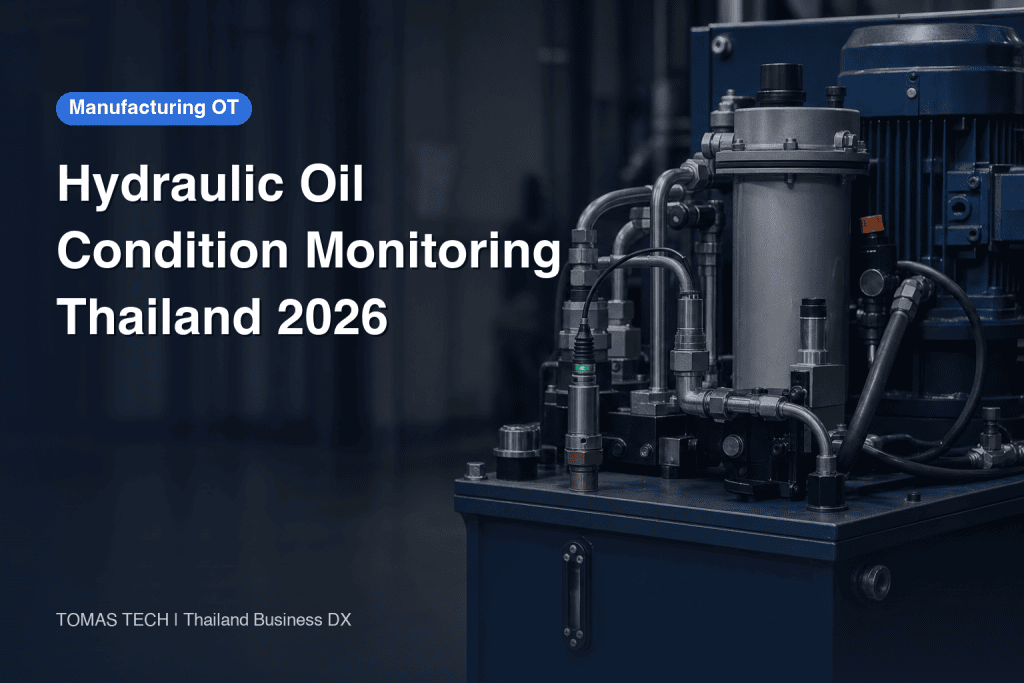
When introducing hydraulic oil condition monitoring, choose the maintenance decision before choosing a sensor model. Particle contamination, water saturation, temperature and oil degradation are different questions. Online readings also depend on where and under what operating conditions the oil is measured. This guide takes a Thai factory’s hydraulic power units, presses and moulding machines as examples. It covers measurement scope, bypass installation, alarms, data integration, the request for proposal (RFP), factory acceptance testing (FAT) and site acceptance testing (SAT). It does not prescribe one cleanliness code or oil-change interval for every machine; targets must follow the component OEM’s requirements and the actual fluid and operating conditions.
Start with the decision the condition monitoring system must support
“Dirty oil” does not tell an operator what to do. Break the issue into questions: Did the particle trend recover after a filter change? Is water entering the reservoir? Does a reading rise only at high operating temperature? How will a flushing operation be judged after pump replacement? For each question, record the measurement point, operating state, comparison period, owner and response. Otherwise an attractive dashboard can produce alarms with no agreed action.
Prioritise assets by production impact, replacement-part lead time, contamination history, previous laboratory results and warranty conditions, not merely reservoir size. A main press running continuously may need a different approach from a standby hydraulic unit. Complete the measurement and response workflow on one circuit before extending it to similar machines. That pilot should establish maintenance responsibility as well as wiring and communications.
Separate particles, water, temperature and laboratory analysis
ISO 4406:2021 specifies a code for expressing the amount of solid particles in a hydraulic fluid. A code describes a contamination level; the standard does not set one universal acceptable target for every hydraulic machine. Obtain the target from the pump, valve and other relevant component OEM documents, warranty requirements and operating specification. Keep the document and measurement point with the target in the asset register.
A water-saturation sensor and a laboratory water-content test do not report the same quantity. Relative saturation changes with fluid type and temperature, so the same display does not necessarily represent the same mass of water. Temperature affects viscosity and sensor interpretation but is not a particle count or water-content result. For viscosity, acid number, additives or wear metals, specify appropriate bottle sampling and laboratory tests. Online monitoring identifies a change; it does not prove the full health of the fluid.
| Question | Typical method | Interpretation condition |
|---|---|---|
| Solid particle trend | Particle counter or contamination monitor | Confirm sensing principle, calibration, flow, bubbles and droplets |
| Water ingress | Saturation sensor followed by sampling where needed | Interpret with fluid type and temperature; confirm water content if needed |
| Thermal change | Temperature sensor | Compare load, cooling and measurement location |
| Fluid degradation or wear cause | Laboratory oil analysis | Keep sample point, container, test panel and history consistent |

Know what ISO 4406, ISO 21018-1 and ISO 11500 each cover
An RFP that merely says “ISO compliant” does not define a measuring instrument. ISO 4406:2021 codes the solid-particle level. ISO 21018-1:2024 discusses techniques for monitoring particulate contamination with monitors that cannot be calibrated under ISO 11171 and the relative merits of selecting them for an application. Its public abstract includes general cleanliness, flushing progress and support equipment or test rigs. Its note also cautions against treating such monitors as particle counters merely because they may use similar physical principles.
ISO 11500:2022 covers automatic light-extinction counting of particles in bottle samples of clear, homogeneous, single-phase hydraulic fluid. A bottle-sample result and a continuously installed monitor each have advantages and limitations. Compare them only with the sampling method, operating state and measuring principle recorded. Ask suppliers to specify the standard edition, calibration or correlation procedure, unit and method of reporting the code. A standard number alone does not guarantee accuracy or agreement between two methods.
Select sensors by measuring principle and operating envelope
An online particle counter and a particulate contamination monitor may show similar screens while relying on different calibration claims. Check whether the fluid, optical characteristics, viscosity, temperature, air entrainment, water droplets, contamination range, flow and pressure fit the proposed instrument. A credible instrument should expose low flow, sensor fouling and invalid measurements separately from an actual high contamination reading. Otherwise a plausible number may be displayed outside the valid range.
The HYDAC contamination-sensor catalogue illustrates available particle, saturation and temperature functions; it is an example of technical options, not an endorsement of a model for a particular machine. Request proof of fluid compatibility, hydraulic connection, maintenance, calibration, output data and local service. If one device reports several variables, assess each variable’s principle and limitations separately.
Choose representative sampling points and design the bypass
A reservoir, pump inlet, return line and points before or after a filter can show different conditions. Draw the reservoir, pump, pressure circuit, return, filter and cooler on the hydraulic drawing. State exactly which oil flow each reading represents. A sensor on a closed branch or stagnant dead leg can show a reassuring number while the circulating fluid deteriorates.
For a bypass or side-stream arrangement, document extraction and return points, the method of maintaining flow, pressure drop, air release, isolation valves, spill containment and relation to the pump and filter. Confirm with the product datasheet whether direct main-line pressure is permitted. Leave space for safe cleaning, checking and replacement. HYDAC’s sensor-module information shows a pump and air-release path as one implementation example; do not import its limits into another machine. At SAT, verify the actual bypass flow under normal operation. A bypass on a drawing is not proof of representative sampling.

Set targets from OEM requirements and the machine’s own baseline
There is no responsible answer to “Which ISO 4406 code should we use?” without identifying the machine, fluid and sensitive components. Gather the OEM fluid and cleanliness requirements, warranty terms and service documents. If different documents appear to conflict, check their scope and measurement location. If no valid target can be found, record it as unresolved and consult the OEM or authorised maintenance owner. Do not label a guessed value as an ISO requirement.
Build a baseline during known normal operation. Keep fluid, asset, operating state, measurement point, flow, temperature, particle trend, saturation and bottle-sample results together. Record oil top-ups, filter changes, pipe openings and pump work. Compare their effects before setting initial alarms. If alarms become frequent, examine measurement validity and the cause before simply relaxing thresholds. This history makes future changes interpretable.
Make an alarm a condition plus an action
An alarm definition needs a condition, persistence rule, clearing rule, owner and first response. A short particle spike may follow an intervention or be influenced by bubbles. Check persistence and supporting signals such as temperature and flow. Critical protection conditions specified by the machine OEM take priority; the monitoring dashboard must not silently replace a safety interlock.
Separate “check,” “plan work” and “operating decision” levels where the equipment risk warrants it. An operator might inspect leaks, filter differential pressure, oil top-up records, water ingress paths and cooling, then request sampling. Record who checked which point, the intervention and the follow-up result. Acknowledging a notification is not proof that the fault has been resolved.
| Alarm pattern | First checks | Possible next step |
|---|---|---|
| Particle rise | Flow, bubbles, work history, filter condition | Repeat measurement, sample and investigate source |
| Saturation rise | Temperature, reservoir breathing, cooler, top-up | Verify by analysis and inspect ingress path |
| Temperature rise | Load, cooling and measurement location | Compare with OEM operating conditions |
| Missing data | Power, communications, flow and device diagnostics | Restore monitoring and mark the gap |
Use bottle samples to corroborate online trends
Take samples near the online measurement point and relevant time wherever practical. Standardise sample-port preparation, container cleanliness, labelling and transport. Send the asset ID, fluid, operating state, sampling location, time and recent maintenance work with each bottle. Even when ISO 11500 is specified, confirm which method the laboratory actually performs and how it reports its results.
A lab can examine more than particle count. Discuss water content, viscosity, acid number and wear metals with the lab according to the fluid and failure hypothesis. A rising saturation signal alone does not automatically require an oil change. Detect the change online, inspect the circuit and maintenance history, order the needed analysis, and then choose the response. Bosch Rexroth’s fluid-management page is an example of fluid management as a maintenance discipline; assess any service against your own asset needs.
Carry measurement context into OT and maintenance systems
Sending one cleanliness code to a PLC is rarely enough for root-cause analysis. Define raw or channel-level particle values where available, the code, temperature, saturation, flow, device status, timestamp, asset ID, sampling point and units as one data contract. Verify whether the proposed analogue, contact, serial or industrial-network interface actually exposes each required field. FAT should exercise the real data path, not only show a dashboard mock-up.
Specify clock synchronisation, communication loss, buffered data, gaps after reconnection, inspection mode, sensor replacement ID and calibration history. Log changes to thresholds and recipients. Connect an oil alarm to the asset and work-order records described in the equipment maintenance management guide. If the machine also needs rotating-equipment diagnosis, use the same asset ID and clock to compare the information in the vibration sensor diagnostics guide. A coherent timeline helps technicians evaluate multiple hypotheses.

Put the Thai plant’s actual constraints into the RFP
Inspect cabinet temperature and humidity, cleaning and oil mist, access for maintenance, power and grounding, network availability, spare-part lead times and working languages at the site. Do not infer conditions solely from regional climate. Compare the measured cabinet environment with the device rating and separately check the hydraulic side for pressure, vibration and leaks. Include the site’s isolation, lockout and used-oil handling rules in the installation plan.
Attach the machine drawing, fluid, measured operating pressure, temperature and flow ranges, possible measurement points, decision use cases, previous lab results and OEM cleanliness requirements. Request a common response format for measuring principle, compatibility, connection drawing, communication fields, calibration and maintenance, consumables, local support, tests and training. A one-line purchase-price comparison can omit pipe modifications, sampling, data collection and recurrent work. Align the scope and exclusions before comparing bids.
Compare offers on capability and operating burden
Check that each measurement principle addresses the intended failure hypothesis. Confirm fluid compatibility and the continuous operating range rather than assuming a catalogue maximum applies throughout operation. Compare validity diagnostics, calibration or correlation method, maintenance frequency, raw data access, alarm-change audit trail and spare availability. Ask the vendor to distinguish normal from temporary operating conditions in writing.
Manufacturer literature such as Parker’s hydraulic filtration reference can help identify filtration and contamination-control options. Do not transfer a product example or recommended value into an unrelated machine without checking its component requirements. Filtration alone may not address water or chemical ageing; particle monitoring alone does not represent the entire fluid condition. Each proposed measure should name the problem it addresses.
Include an acceptance-condition template in the RFP
List the asset number and model, fluid type, reservoir, measured pressure, temperature and flow during normal running and start-up, existing filters, sampling points, wiring route, PLC interfaces, network restrictions and available shutdown window. Mark unknowns for a site survey rather than inventing numbers. Cite the OEM document, edition, sensitive component and measuring point behind the cleanliness target.
Require vendors to respond separately for particle sensing and calibration, fluid compatibility, saturation and temperature, bypass flow, pressure, air-entrainment diagnosis, cleaning, spares, output tags, protocol, local support and installation boundary. Ask for the supporting datasheet and conditional statements, not a bare “compliant.” Check with the machine owner whether hydraulic modifications affect warranty.
For FAT, create columns for test ID, simulated input, expected display, recipient, recorded data and failure-state display. For SAT, record the installed piping, leak check, valve position, flow under operation, start-stop behaviour, sample location and maintenance demonstration. When comparing with a lab, define sample point, time, operating state and measurement method first. Agree actual numerical acceptance values in the contract from the machine and product conditions.
FAT: test the decision chain, not just the wiring
FAT should check panel and software functions, tags, units, timestamps, disconnect and recovery, device faults, threshold-change history, notifications and visualisation. Mark simulated inputs as simulations, not evidence that the real oil has been measured correctly. Verify channel order, rounding, invalid-state displays and trend retention. Keep asset and sample-point identifiers unchanged across PLC, historian and maintenance system.
An acceptance case should trace input, sensor or simulator, PLC, historian, notification and work order with expected result, actual result, evidence and owner. After a communication break, missing values must not be silently filled with zero or normal readings. Test that technicians can record an inspection from a simulated alarm. Safety-control validation remains subject to the machine’s separate approved procedure.
SAT: check real flow, real oil and the people who respond
At site, compare the as-built pipework with the approved drawing. Check leaks, isolation, venting and the actual flow, pressure and temperature against instrument limits during normal operation. Identify periods when start-stop cycles or filter switching interrupt flow and mark the associated values invalid. Compare trends with properly documented bottle samples; do not make perfect agreement with a lab a condition without accounting for the different sampling and measurement methods.
Train local maintenance staff to sample, diagnose an alarm, inspect the sensor, arrange cleaning or calibration, identify spares and read the report. Provide Thai operating instructions, with English technical material where useful to the team. Review early alarms, missed events, missing data and operator actions. Set the review period and machine-specific pass criteria in the contract rather than importing a generic number from an article.
Example: a particle increase on a press return line
If return-line particle values rise, record the time, asset ID, fluid temperature, flow and device state along with the particle data. Inspect load, changeover, top-up, filter and hydraulic repair history. A return-line reading alone cannot prove that the pump is wearing. If several branches feed the return, use targeted inspection or sampling to locate the source.
Confirm valid flow, bubbles, droplets, sensor condition and calibration status. Sample as close as practical to the event and in the specified operating state; check filter pressure and the reservoir as well. A simultaneous saturation rise may point to a water-ingress hypothesis. After a response, compare under comparable conditions. The maintenance record should show the alarm, inspection, lab request, hypothesis, work and repeat measurement. This is a decision workflow, not a universal shutdown particle code.
Establish ownership of data and maintenance actions
Assign ownership of measurement points and alarms to maintenance, time and communications to OT, and laboratory records to the relevant quality or analysis team. Define approval for changes. Link asset, point, sensor serial number, fluid and oil-change date in a register. A sensor replacement can create an apparent step in a trend; retain the model, calibration, method and settings before and after the change.
Choose raw or aggregated long-term storage according to failure horizons, plant retention rules and network capacity. Document aggregation and treatment of gaps. Keep the threshold version that was active when an historical alarm fired. Test whether a network outage is visible, local values can be retained, restored timestamps are ordered and a sensor fault can be distinguished from a fluid abnormality. Include diagnostics, spare identification and calibration requests among deliverables so staff can operate the system after handover.
Roll out in a sequence that preserves learning
First gather assets, failure hypotheses, OEM requirements and sampling history. Then define measurements and locations, verify sensor principles, design bypass, power, communication and service access, and issue a scoped RFP. FAT checks tags, data and alarms; SAT checks actual flow, fluid trends and operator action. Review the baseline and alarms before routine operation. This order reduces redesign after hardware purchase.
Use common asset IDs, timestamps, fields and work records from the first pilot so later units can be added coherently. It is still reasonable to install different sensor combinations on different machines. Review whether alarms led to inspections, causes and completed work, how often sample and online values could be compared, why data was missing and whether notifications were useful. Do not claim a causal reduction in breakdowns or oil use from a short before-and-after comparison that also includes changes in production or maintenance.
Frequently asked questions
What should hydraulic oil condition monitoring measure?
That depends on the asset’s failure hypothesis. Particle monitoring addresses solid contamination; saturation helps flag potential water ingress; temperature provides thermal context. Bottle samples and laboratory analyses are needed for fluid chemistry and wear questions. Even a combined device has separate measurement limits for each output.
Is there a universal ISO 4406 target?
No. ISO 4406 expresses particle contamination as a code; it does not prescribe the best level for every pump, valve and operating condition. Set the target from OEM documents, warranty, fluid and the specified measurement point, and document any later change.
What if online and laboratory results differ?
Compare location, time, operating state, flow, bubbles, droplets, fluid, container condition and methods before declaring one result wrong. Repeat a sample or device diagnostic where necessary. A continuous monitor and a bottle-sample particle counter may not be equivalent measurements.
Does a sensor remove the need for oil analysis?
No. Continuous particle, saturation and temperature trends can identify change early, while viscosity, acid number, additives or wear metals require appropriate tests. Use an online alarm to trigger targeted inspection and analysis before selecting the intervention.
Summary
A reliable hydraulic oil condition monitoring project starts with maintenance decisions and OEM requirements, separates particle, saturation, temperature and lab-analysis questions, and chooses representative, maintainable measurement points. The RFP should specify principle and installation scope. FAT verifies data and alarms; SAT verifies actual fluid, flow and the people who respond. Linking the reading to maintenance evidence is what makes the system useful over time.
For help mapping measurement points or preparing an RFP, contact TOMAS TECH. A discussion can begin with your existing drawings and sampling records, even while some inputs still require site confirmation.


