


Introduction: SMT Mounter Traceability Means Deciding How Finely to Record and Where to Stop Errors
The trigger for revisiting SMT mounter traceability is usually a single email from a customer: “We suspect a problem with this capacitor lot. Please send us the serial numbers of the boards that carry it as soon as possible.” Yet all you have on hand are component issue records per work order and daily production totals. You cannot say which reel was loaded onto which feeder at what time, or which boards it went into, so in the end you report “everything that line built that week” as the affected scope.
At Japanese SMT plants in Ayutthaya and Chonburi, Thailand, the number of product variants has grown, and so has the number of changeovers. During a night-shift changeover, an operator pushes a feeder cart up to the line, reads the label on each component reel with a handheld terminal, checks the screen, and moves on to the next slot. Reels with smudged, unreadable labels are keyed in by hand, and the only record of who confirmed the verification result, and when, is a paper check sheet. This situation is far from unusual.
Here is the argument of this article up front. SMT mounter traceability is not a question of “whether to keep records” but of deciding the following six points.
- Granularity: Do you hold reel IDs per work order, hold the reel loaded at the time for each board, or pin down the exact components used, including the timing of splices and reel changes? This is something to agree on with the customer.
- The record chain: Linking four things without gaps, namely the component reel, the feeder, the mounter slot and the board serial. If any one link breaks, granularity drops a level.
- Mechanisms that stop errors: Verifying at setup and at splicing, and not allowing production to start if there is a mismatch.
- Integration with upper systems: Deciding what to send to the MES over IPC-CFX by capability names and message names, not by the phrase “CFX compatible”.
- How the benefit shows up: The number of boards you have to investigate when a component lot is suspect changes with the granularity of your records (this article runs an estimate with assumed figures).
- Purchasing and acceptance: Writing all of this into the RFP and actually loading wrong reels during FAT/SAT to test it.
This article does not recommend or compare any specific mounter or software. Each vendor’s capabilities are presented as what that vendor describes in its public materials. The estimate in the second half is a model calculation based entirely on assumed figures.
For the overall picture of electronics traceability (the units to trace and the cost layers), see “Electronics Traceability 2026 | Four Units to Trace, Five Cost Layers“. This article narrows that picture down to the mounter process.
What Is SMT Mounter Traceability: Which Records Does It Link?
In a nutshell, SMT mounter traceability is a record that can answer both “Which reel did the component at this position on this board come from?” and the reverse, “Which boards did the components from this reel go onto?”
That record is made up of the following chain.
- Component reel: component manufacturer, manufacturer lot, date code, an in-house reel ID, and moisture sensitivity level (MSL)
- Feeder: the feeder ID, and which reel was loaded onto which feeder
- Mounter slot and table: which feeder was inserted into which position on which machine
- Board serial: the identifier of the board that passed through that machine at that time
- MES and traceability database: where these are linked by time and stored in searchable form
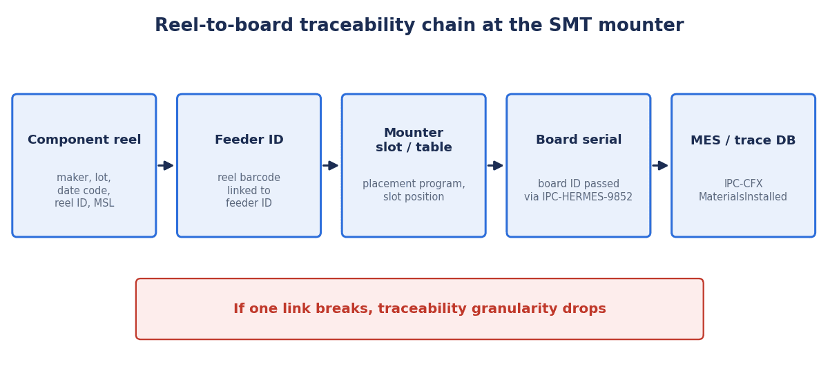
If any link in the chain breaks, granularity drops. For example, even if you record the pairing of reel ID and feeder ID at setup, if reel changes are recorded only on a paper check sheet, you cannot determine board by board whether the reel before or after the change was used. Likewise, if board serials are read at only one point at the head of the line and the machines along the way cannot pass the board ID on, you end up matching mounter records to board serials by timestamp, and adjacent boards get mixed up.
Another important point is that the record chain is not completed “inside the mounter” alone. Reel IDs should ideally be issued when components are received. If the correspondence between the receiving label and the manufacturer’s label is unclear, then no matter how precisely you record at the mounter afterwards, you cannot trace back to the manufacturer lot. How to approach identification and release for use at receiving is covered in “Receiving Inspection System Implementation: From Supplier Rules to Release“.
Thinking About Granularity: IPC-1782 and the M1 to M4 Levels as Explained When It Was Drafted
A common yardstick for discussing granularity is IPC-1782, IPC’s traceability standard.
According to the publicly available table of contents and scope of IPC-1782B, the latest edition is Revision B (September 2023), which supersedes Revision A (November 2020) and the original edition (October 2016). Its full title is “Standard for Manufacturing and Supply Chain Traceability of Electronic Products”. The scope states that it sets minimum requirements for manufacturing and supply chain traceability based on perceived risk, applies to PCBA manufacturing, mechanical assembly and PCB fabrication, and covers both internal traceability within an assembly site and external traceability between sites. The minimum requirements are structured as four levels each for materials and for processes, and are described as mapping to IPC classes and end markets (such as automotive).
The table of contents shows a section on a traceability cell dedicated to SMT placement, alongside chapters on material traceability cells, traceability of individual materials, requirements for computerized systems and external traceability (such as tamper-proof event records). The purpose section also mentions that the standard helps reduce counterfeit components and that it recommends automated data collection. However, you cannot tell exactly which items the SMT placement cell contains without checking the body of the standard (which is paid).
For the content of the levels, a useful reference is a 2016 explanatory paper by Michael Ford (then at Mentor Graphics), who was involved in drafting IPC-1782. That paper dates from the drafting stage, so you need to check the body of the standard to confirm whether the current Revision B says the same thing. According to the paper, there are four levels each for materials (M1 to M4) and processes (P1 to P4), which can be combined freely, for example “M3 and P1”, and are decided by agreement between the user and the supplier.
| Level | Description of material traceability in the 2016 explanatory paper (summary) | How to read it for the mounter process |
|---|---|---|
| M1 | Listed per work order by part number and receiving order | Only as far as “this part number was used on this work order” |
| M2 | Listed per batch or work order by unique material ID | Hold a list of the reel IDs used, per work order |
| M3 | Listed per board (PCB-A) by the unique material IDs that were loaded (within process constraints) | Hold, for each board, the reel IDs that were on the feeders at that time |
| M4 | Exact record of the materials actually used on each board | Pin down the components used on each board, including the position of splices and changes |
The same paper describes Level 4 as a state in which there is no doubt about where materials were changed or replenished during assembly. As example items for the SMT placement cell, it lists material change events, verification events, automatic splice detection, remaining exposure time for each MSD component and the actual nozzle used for each reference designator. For reels, it sets out the idea that when one reel is used across many boards, each board’s record should hold the reel ID, while the information about the reel itself is held only once elsewhere.
The key point here is that the standard does not uniformly dictate which level to aim for. The level is decided by agreement between customer and supplier according to the product’s risk and the customer’s requirements. Before deciding internally that “it has to be M4”, you need to set the customer’s requirements side by side with how much your lines can actually record.
What Granularity Changes: The Scope of a Component Lot Investigation
The difference in granularity matters in practice after a problem occurs. When a component manufacturer notifies you of a lot defect, or a failure is found in the field, granularity determines how narrowly you can identify “which boards are affected”.
It is not about the placement process, but one example of records shaping the affected scope is Honda’s recall report submitted to the US NHTSA (18V-664, 2018). It concerned the risk that, in the manufacturing process of a Denso SRS unit, a bent ground pin at the flash programming station could damage the board’s circuit pattern. The report explains that the recall population was determined based on manufacturing records, and that because there is 100% traceability between suspect units and vehicles (VINs), vehicles of the same model not included in the recall have good units installed. The potential population was 118 vehicles, of which 19 Insight vehicles were produced between August 23 and 30, 2018. The cause was not a mounter, but the example shows that linking manufacturing records to individual units made it possible to narrow the scope to a specific period and specific units.
On the other hand, there are errors that mounter verification cannot prevent. Weldon’s (Akron Brass) recall report (22E-037, 2022) states that in a multiplex communication module, a terminating resistor that should have been fitted only on the harness side was also mounted on the board, lowering the CAN bus resistance and creating a risk of losing communication. The potential population was 860 units, the production period was January 21 to April 29, 2022, and the company stated that it holds serial numbers and shipping data. The cause was an error in the BOM, not a mounter misload.
What this example shows is that setup verification checks whether “the components on the machine match the program and BOM”; it cannot find errors in the program or BOM itself. Even with a verification system in place, you still need separate engineering change control and first-article checks. How to separate the errors that verification can prevent from those it cannot is also covered in “Material Misfeed Prevention 2026: What Works Is Removing the Error Conditions, Not Faster Verification“.
How Setup Verification Works: Offline and Online Setup, and Blocking Production Start
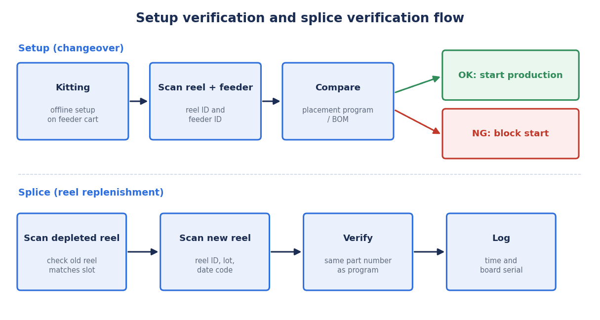
What an SMT component verification system checks comes down, basically, to three matches.
- Is this reel (component part number) loaded on this feeder?
- Is this feeder inserted at the correct slot and table position in the program?
- Does that combination match the placement program and BOM of the product about to run?
There are two kinds of setup: offline setup (also called kitting), where reels are loaded onto feeders away from the line and grouped on a cart, and online setup, where feeders and reels are changed on the machine itself. In both cases the flow is the same: read the barcodes on the reel and the feeder, compare them with the program, and if there is a mismatch, raise a warning and stop production from starting.
Vendors describe this in their public materials as follows.
- Panasonic: The company says the Material Verification module of PanaCIM Gen2 can use a handheld barcode scanner to verify that the correct components are loaded on the feeders during product changeover, setup, splicing and component run-out. Its catalog states that it writes component data into feeder memory, verifies at the equipment level and controls production start to prevent misplacement.
- ASMPT: The company says WORKS Preparation guides operators through setup with light signals and verifies the entire setup on the feeder table, aiming for error-free production from the start.
- Yamaha: The company says the component setup verification function of YSUP prevents incorrect setup states, and that it supports offline setup using an offline setup station and feeder carts.
- FUJI: The company says Nexim supports error-free, efficient changeovers through navigation for component picking and feeder setting.
- JUKI: Parts Verification and traceability are listed among the data functions of the company’s JaNets. In a 2005 document, the company described its SCS (Setup Control System) of that time as using wireless handheld terminals to confirm that the correct component was in the correct position when reels or feeders were changed, and using an interlock to stop production until verification was complete.
As that 2005 document shows, the mechanism of “verify by barcode and stop with an interlock if it does not match” is itself a mature technology that has existed since the 2000s. What is new is less whether you verify than where you record the verification results and how far you connect them to upper systems.
In practice, what you need to decide is “who can release a verification NG, with what authority, and after checking what”. It can happen that a verification NG comes up on the night shift, the line leader is unsure what to do, and production is restarted with a skip operation. Who can release the interlock, and whether the fact of the release and its reason are kept on record, should be decided before implementation, more as an operating rule than as a system function.
One more point: how reliable verification is depends on whether the barcodes can be read. If manual entry increases because reel labels are poorly printed or handheld terminals lack reading performance, verification loses much of its meaning. Label quality is covered in “Barcode Verifier: Print Quality Grades and RFP for Thai Plants“, and choosing fixed-mount readers in “Fixed-Mount Code Reader Selection — Resolution, Lighting, DPM and RFP for Thai Factories“.
Recording Splices and Reel Changes
Even in plants that have introduced setup verification, splicing is easy to overlook. When components run low during production, the tape of a new reel is spliced on without stopping. Separately from changeovers, splicing happens repeatedly during production. If a reel with a different part number is spliced on at this point, the setup verification has already passed correctly, so the error is noticed only at a downstream inspection or, in the worst case, in the field.
Whether you need splice verification ties directly to the granularity discussion. If you want to pin down which reel’s components were used on each board (equivalent to M4 in the explanation from the drafting stage), records of when splices occurred are essential.
Vendors describe mechanisms such as the following.
- Panasonic: The company says it verifies the old material before splicing the new one. The company also says its intelligent feeders with memory remember up to four reels loaded onto a feeder.
- Cogiscan: The company says that during splicing, its TTC Go mobile app has the operator scan both the new reel and the nearly depleted reel to confirm component continuity. This is an example of a third-party solution that does not depend on the mounter manufacturer.
- Yamaha: The company says a threshold for the remaining reel quantity can be set so that replenishment by splicing takes priority.
The shop-floor challenge in putting splice verification into routine use is the extra work. Because splicing is done without stopping production, operators are tempted to skip scanning steps as they increase. You need both system-side measures, such as not treating a splice as complete until both the old and new reels have been read, or raising a warning when a certain number of placements are made without verification, and shop-floor measures, such as attaching labels where they are easy to scan.
For the record, what matters is not only the time of the splice but also being able to tell which board serials were passing through that machine at that time. Because the source of the components changes at the splice point, you need information that lets you decide which reel to attribute the boards near the boundary to.
Managing Feeder, Reel and Nozzle IDs
To link the record chain mechanically, feeders as well as reels need unique IDs. Whether the pairing of reel ID and feeder ID, and of feeder ID and slot position, can be captured automatically changes how many scans operators must do and how reliable the records are.
Mycronic says it gives magazines and Agilis feeders unique IDs so that quantity, position, MSD data and batch codes can be checked at any time during production. Its materials state that a unique barcode identifies a specific reel and links it to a specific feeder, and that the machine automatically detects the reel’s position from the feeder ID. Panasonic’s writing of component data into feeder memory is a mechanism along the same lines.
On the other hand, Thai plants sometimes have mounters and feeders of different generations side by side in the same factory. Newer lines may have intelligent feeders, while older lines have feeders without IDs, and operators scan after visually checking the slot number. In that case, on the older lines the record chain depends on “manually entered slot numbers”. Whether to require the same granularity on every line, or to start with the lines that run products with the strictest customer requirements, needs to be decided together with your equipment replacement plan.
As for nozzles, the 2016 explanatory paper lists “the actual nozzle used for each reference designator” among the example items for the SMT placement cell. However, this is an example from the explanation at the drafting stage, and how much to record is determined by agreement with the customer and by what data the mounter can output. Regarding component recognition images, Yamaha says YSUP can save all of a mounter’s component recognition images. Recognition images and nozzle records serve not only to establish where components came from but also as material when you want to check the placement condition after the fact.
General design of histories that link equipment condition to products is covered in “Production Equipment Traceability: Machine-to-Part RFP and FAT/SAT“.
Integration with MSD Control and the Component Warehouse
Reel records start before the reel is loaded onto the mounter. Moisture-sensitive devices (MSDs) start absorbing moisture once the moisture barrier bag is opened, and if their floor life is exceeded they may be damaged during reflow. In the J-STD-033 table cited in a TI document, the floor life for each MSL is defined under the conditions of 30°C or below and humidity at or below a set level. Time spent on the mounter also consumes floor life, so you need to decide whether the remaining time is held on the mounter side or the MES side. For details of MSD control, see “MSD Management System: Floor Life Tracking, Dry Storage and RFP for Thai SMT Plants“.
On warehouse integration, ASMPT says its Factory Material Manager assigns a unique ID (UID) to each package and container at receiving, links quantity, part number, manufacturer, batch number, receiving date, moisture sensitivity and expiry date to it, and scans the UID every time it moves location. It states that consumption on the line is reported through a standardized interface, and that issuing takes first-in, first-out (FIFO) order and MSD exposure time into account. ASMPT also says WORKS Preparation has MSD and expiry date management functions.
Panasonic says Material Control manages remaining quantity by a unique ID for each component (Reel ID) and provides MSD lifetime management and search for defective components and lots (narrowing down recall candidates). FUJI says Nexim manages component location, remaining quantity and floor life. Yamaha says YSUP monitors the setup time and production time of MSL components. JUKI says the ISM Interface of JaNets extracts the list of required components from the production program and sends it to the storage tower (ISM).
The key design point is to “track the reel ID issued at receiving through the warehouse, setup and line consumption under the same ID”. At plants that relabel reels with in-house labels at receiving, the starting point for tracing back is whether the manufacturer label information (lot, date code) is carried over correctly to the in-house ID. For the basics of lot and inventory management, also see “Lot Management System Guide – Basics, Costs and Rollout 2026“.
Passing Board IDs Along: IPC-HERMES-9852
To link component records to board serials, the mounter needs to know “which board it is placing on right now”. This is the role of IPC-HERMES-9852 (The Hermes Standard), a standard for passing board information from machine to machine.
According to the Hermes specification, the standard replaces the electrical interface of the earlier SMEMA (IPC-SMEMA-9851) and uses TCP/IP and XML to convey the board’s unique ID, the ID of the equipment that first detected the board, the barcode, conveyor speed and product information (product ID, length, width, thickness), among other things. The board ID is a GUID generated by the first machine in a continuous section of Hermes-enabled machines and passed from machine to machine. The official Hermes website says every board in assembly can be tracked without re-reading barcodes or ID tags at each machine.
Version 1.6 in 2024 added fields for top-side and bottom-side barcodes, and its appendix also describes special scenarios such as tracking a board removed from the line. The latest is Version 1.7 (June 2026), whose table of contents shows new messages for exchanging extended board information.
The point that needs the most attention in practice is the following behavior described in the specification. If a machine that does not support Hermes is placed in between, the board ID is lost there, and the next Hermes-enabled machine generates a new ID. If even one of the printer, SPI, mounter, reflow oven and AOI, or a conveyor, does not support Hermes, the same board gets a different ID before and after it. Even if you read the board serial at the head of the line, once the ID is broken partway, linking mounter records to board serials requires matching by timestamp, and granularity drops.
Also, what Hermes handles is the passing of board IDs and board information. It is not a standard that defines component (reel) traceability. The role of sending component records to the MES falls to IPC-CFX, explained next, and to mechanisms on the MES side. It helps to think of it this way: horizontal integration (tracking the same board from machine to machine) is Hermes, and vertical integration (sending from machines to the MES) is CFX. Board-level record integration with print inspection and reflow is covered in “Solder Paste Inspection in Thailand: SPI Selection, MES Integration and FAT/SAT” and “Reflow Profile Management: Continuous Oven Monitoring, Board-Level Records and RFP“.
Integration with the MES: IPC-CFX
IPC-CFX (IPC-2591, Connected Factory Exchange) is an open standard for exchanging information in both directions between manufacturing processes and upper-level host systems. According to IPC’s product page, it covers automated, semi-automated and manual PCBA processes, and the standard document is paid.
The latest version is V2.0, announced in April 2025. According to IPC’s announcement, V2.0 expands the number of supported equipment types to 14 (adding hand soldering and wave soldering) and adds messages for AGVs and AMRs, per-component pick-and-place cycle information in SMT placement, logging of dynamic recipe changes during production, and fields for tracing board variations such as board vendor identification. The V2.0 SDK is described as backward compatible with earlier SDKs.
For what is mandatory and what is optional for a mounter, IPC publishes a table of mandatory and optional capabilities by equipment type. However, the table we were able to confirm is the one as of V1.3 (2021), and we have not confirmed whether V2.0 is the same. The SMT mounter (Pick and Place) column of the V1.3 table reads as follows.
| Capability (name in the V1.3 capability table) | Treatment for SMT mounters (V1.3) | Main corresponding messages |
|---|---|---|
| Exact Material Trace with External Setup | Mandatory (M) | MaterialsInstalled |
| Exact Material Trace with Internal Setup | Mandatory if equipped with a barcode or RFID reader (MR) | MaterialsInstalled |
| Internal Setup Validation | Optional (O) | GetLoadedMaterialsRequest/Response, MaterialsLoaded, MaterialsUnloaded, ValidateStationSetupRequest/Response |
| External Setup Validation | Optional (O) | GetRequiredSetupRequest/Response, SetupRequirementsChanged, LockStationRequest/UnlockStationRequest |
| Offline Setup | Optional (O) | MaterialCarriersLoaded/Unloaded |
| Material Blocking (External/Internal) | Optional (O) | BlockMaterialLocationsRequest, BlockMaterialsRequest |
| Station Locking | Optional (O) | — |
| WIP Tracking | Mandatory (M) | — |
In other words, in the V1.3 capability table, MaterialsInstalled (CFX.Production.Assembly.MaterialsInstalled), which reports “which components were placed”, is mandatory for mounters, but Setup Validation and Station Locking are optional. Writing only “IPC-CFX compatible” in an RFP does not guarantee that setup verification or interlocks linked with the MES will be achieved. It is important to specify the required capability names and message names, and even the target version of IPC-2591.
To check conformance, you can use the IPC-CFX Qualified Products List (QPL). According to IPC, a vendor contracted to the self-validation system self-validates a model and submits it to an automated electronic audit; if it passes, the model is listed on the QPL. In the RFP and FAT, you can make it a check item whether the mounter being introduced is listed on the QPL, and which version of IPC-2591 it was listed under.
Mounter Vendor Software and the MES: Where to Verify and Where to Keep the Records
Setup verification and traceability records can be implemented in mounter manufacturers’ software, in the MES or in third-party solutions. Where to put them is the first design question for the RFP. Lining up what each vendor describes in its public materials gives the following (this does not indicate superiority or a recommendation).
| Company and product | Description in public materials (summary) |
|---|---|
| Panasonic PanaCIM Gen2 | Verification at setup, splicing and component run-out; equipment-level verification via feeder memory and control of production start; remaining quantity management by Reel ID; MSD lifetime management; search for defective components and lots |
| ASMPT WORKS Preparation / Factory Material Manager | Setup guidance by light signals and verification of the entire feeder table; UID assignment at receiving and location management; FIFO issuing and consideration of MSD exposure time |
| Yamaha YSUP | Component setup verification; offline setup; production history search; saving component recognition images; time monitoring of MSL components; MES integration via YSUP-Link |
| FUJI Nexim | Linking and managing panel, component, equipment and inspection data; managing component location, remaining quantity and floor life; navigation for picking and feeder setting |
| JUKI JaNets | Parts verification; traceability; interface to the storage tower (ISM) |
| Mycronic (Agilis feeders) | Unique IDs for magazines and feeders; linking reels to feeders; automatic detection of reel position from the feeder ID |
| Cogiscan (TTC Go) | Having operators scan both the old and new reels at splicing to confirm continuity |
| Aegis FactoryLogix (MES) | Setup verification for SMT assembly machines; MSD management; material receiving and label printing; kitting and issuing; traceability; protocols such as IPC-CFX and OPC UA |
| Siemens Opcenter Execution Electronics (MES) | Full traceability of operations and materials; direct connection to SMT lines and manufacturing equipment; advanced material management |
What this table tells you is that both the mounter manufacturers’ software and the MES products describe setup verification and traceability functions. Where to put them should be considered from the following angles.
- One mounter manufacturer or several: If all your mounters come from one manufacturer, it is easier to complete verification and recording within that manufacturer’s software. If several manufacturers are mixed, putting the functions on the MES or a third-party solution becomes an option for standardizing the verification mechanism and record format.
- Where to keep the master record: Some configurations perform verification in the mounter-side software and send only the results to the MES; others perform verification itself in the MES. Either way, unless you decide which system runs the searches “from board serial to reel” and “from reel to board serial”, you will end up manually cross-checking several systems when a problem occurs.
- Relationship with your existing MES: If you already use an MES, check which messages that MES can receive from the mounters. How to select an MES is covered in “Thailand MES 2026: RFP, 90-Day PoC and Acceptance Guide“.
Model Estimate: Record Granularity and the Number of Boards to Investigate and Quarantine
Let us estimate, with assumed figures, what changes with record granularity. All of the figures below are assumed values for illustration, not actual results from any specific plant. They are also not converted into monetary amounts or defect rates.
Assumptions (all assumed values)
- One SMT line produces 4,800 boards per day over two shifts
- One reel of a certain component (5,000 pieces) is suspected of being defective
- That component is used twice per board, so the boards that used the reel number at most 5,000 pieces ÷ 2 pieces = 2,500 boards
- Issue and return records show that the period in which the suspect reel may have been used is three days
- There was one work order for the relevant product in that period, for 6,000 boards
Number of boards to investigate and quarantine by record granularity
| Record granularity | How the scope is determined | Boards in scope (assumed values) |
|---|---|---|
| Date and line level | Everything that line built during the three days in which the suspect reel may have been used | 4,800 boards × 3 days = 14,400 boards |
| Work-order level (M2-like) | All boards in the work orders on which the suspect reel ID is recorded | 6,000 boards |
| Per-board loaded reel record (M3-like) | Boards whose per-board record contains the suspect reel ID | 5,000 pieces ÷ 2 pieces = up to 2,500 boards |
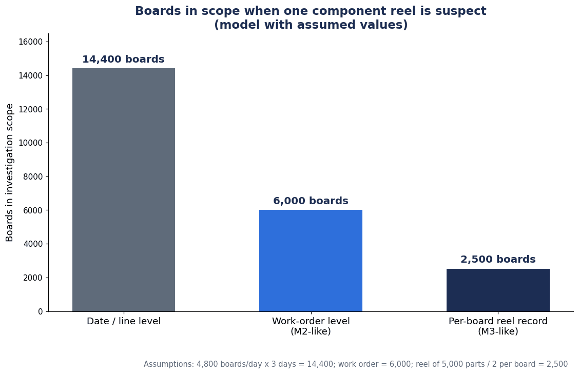
The calculation shows that the scope to investigate is 14,400 boards if you only have date and line level records, and can be narrowed to 6,000 boards if you hold reel IDs per work order, and to at most 2,500 boards if you hold the reels loaded for each board. Whether you can give the customer a list of the affected board serials in your report is also determined by this granularity.
There are four caveats to this estimate.
- All figures are assumed values. Production volume, components per reel, usage per board, the period and work order size vary widely by plant and product.
- The actual number of boards in scope changes with inventory, splices and remaining reel quantities. If a reel was removed partway and returned to the warehouse, or a reel with remaining quantity was reused on another work order, the number of work orders in scope increases.
- It is the customer’s requirements that ultimately determine the scope. Even if your records let you narrow it to 2,500 boards, the customer may ask for a wider scope to be on the safe side. Conversely, if your record granularity is coarse, you cannot show the customer the basis for the scope.
- Even at the M3-like level, if you do not record the timing of splices, the boards just before and after the splice fall into the scope of both the old reel and the new reel. To attribute boundary boards to one reel, you need records of the splice time and the board serials that passed at that time.
Trends in Thailand’s Electronics Industry and Why Now
In Thailand, the electronics sector, and circuit boards in particular, is attracting a large number of investment applications. According to an August 2026 announcement by the Thailand Board of Investment (BOI), over roughly three years from 2023 to mid-2026 there were 880 investment applications in the semiconductor and advanced electronics sector, worth about USD 26.8 billion (about 900 billion baht). Of these, PCBs were the largest, with 224 applications worth about USD 9.85 billion (about 331 billion baht). The BOI says more than half of the world’s major PCB manufacturers have chosen Thailand as a production base. These are investment application amounts, not approved or realized amounts. Also, PCB here refers mainly to bare board fabrication, a process distinct from PCBA, where components are mounted.
On the export side, according to the Trade Policy and Strategy Office (TPSO) of Thailand’s Ministry of Commerce, exports in June 2026 were USD 34,655.9 million, up 20.8% year on year, and by product, circuit boards were up 23.2% year on year. This source does not distinguish whether circuit boards are bare boards or PCBAs. According to a report by The Nation (September 25, 2026), exports in August 2026 were USD 34.62 billion, up 24.3% year on year, the highest growth in 56 months, led by computers and parts, telephones and parts, and ICs.
Krungsri Research’s industry outlook (December 2025) puts the share of PCBs in Thailand’s electronics exports at 2.5%. The same report also projects IC production to grow 3.0% to 4.0% per year in 2026 to 2028. These figures differ in period and definition, so they cannot be added to or compared with the BOI figures.
None of these figures directly calls for mounter traceability. However, as customers in the electronics sector increase and the share of demanding customers such as automotive electronics grows, there will be more situations in which being able to answer inquiries at the component lot level is a precondition for doing business. Plants that handle automotive electronics boards are also subject to IATF 16949 requirements. According to publicly available commentaries and clause quotations, clause 8.5.2.1 of IATF 16949 does not uniformly set traceability granularity; rather, it requires a risk-based traceability plan and a system that can identify and segregate nonconforming and suspect product and meet the response times required by customers and regulations. Identification of individual products by serial number is positioned as a requirement where specified by the customer or by regulations. This is covered in more detail in “IATF 16949 Traceability: Building an Audit-Ready Evidence Chain“.
Implementation Steps: From a Record Inventory to One Line, Upper-System Integration and Rollout
A realistic approach is to proceed in the following four stages. Durations vary widely with plant size and how well existing equipment supports these functions, so read the figures below as rough guides.
Step 1: Take inventory of current records (guide: a few weeks)
First, pick one past lot and actually test how far your current records can produce “the board serials that carry this component lot”. Follow receiving labels, warehouse issue records, setup check sheets, mounter logs and inspection equipment records in order, and find where the chain breaks. At the same time, extract from contracts and quality requirement documents what your main customers require for traceability (granularity, response time, retention period). At this stage, draft the granularity you will aim for (M2-like, M3-like, or including splices).
Step 2: Launch verification and recording on one line (guide: a few months)
Choose one line that runs products with strict requirements, and launch reel ID issuing at receiving, setup verification, splice verification and linking to board serials. Here, firm up operations including the rules for releasing the interlock on a verification NG, the procedure when a label cannot be read, and training for night-shift operators. Providing shop-floor operators with Thai-language procedures and screen displays, and adjusting the scanning steps to the actual flow of work, is what decides whether the system takes root.
Step 3: Upper-system integration (guide: a few months)
Send mounter records to the MES or traceability database so that reverse lookup from board serial and forward lookup from reel can be done on a single screen. At this stage, confirm whether board IDs are continuous within the line via Hermes and which CFX messages to use.
Step 4: Rollout
Extend the operations and RFP format established on one line to other lines. On lines where older mounters remain, decide the scope of support in line with the timing of equipment replacement.
12 Items to Write in the RFP
In the RFP, rather than phrases such as “traceability support” or “CFX compatible”, write the following 12 items concretely.
| No. | Item | Examples of what to write in the RFP |
|---|---|---|
| 1 | Target granularity | Which level to aim for in terms of the IPC-1782 approach (as agreed with the customer); per work order, per-board loaded reels, or including splice timing |
| 2 | Record chain | Which of reel ID, feeder ID, slot and table, and board serial is recorded, at what point, and by which device |
| 3 | Reel ID issuing | Who issues the ID at receiving, and how the manufacturer’s lot and date code are carried over |
| 4 | Setup verification | What is verified against what, for offline setup and online setup respectively |
| 5 | How to stop on a verification NG | Whether production start is blocked (interlock), who has authority to release it, and the record of release |
| 6 | Splice verification | Scanning both old and new reels, verifying the old reel beforehand, recording splice time and board serials |
| 7 | Feeder and nozzle management | Whether feeders have IDs, automatic pairing with reels, scope of recording for nozzles and recognition images |
| 8 | MSD and warehouse integration | Whether remaining MSD time is held in the mounter or the MES, integration with warehouse locations and FIFO |
| 9 | Board ID passing | IPC-HERMES-9852 support status of every machine on the line, and how to keep board IDs connected if some machines do not support it |
| 10 | Upper-system integration | IPC-2591 version, required capability names (Exact Material Trace, Setup Validation, Station Locking, etc.) and message names, whether listed on the QPL |
| 11 | Retention and search | Record retention period (decided in-house to match customer requirements), search in both directions from serial to reel and from reel to serial, response time target |
| 12 | Operation and training | Thai-language screens and procedures, training including the night shift, procedure when labels cannot be read, support and maintenance arrangements |
Item 10 is especially important. As noted above, in the V1.3 capability table, setup verification and station locking are optional capabilities for mounters. If you place an order having written only “CFX compatible”, it can happen that MaterialsInstalled is sent but setup verification linked with the MES turns out not to be included.
The response time in item 11 is the time you can take from receiving an inquiry from the customer to producing a list of the affected board serials. Confirm the customer’s requirement, and make it a condition in the RFP that searches can be completed within that time.
Acceptance Test (FAT/SAT) Check Items
Verification and traceability systems cannot be validated by a test that only runs a correct setup. Deliberately introduce errors and check whether the system stops and whether records are kept. The following are example check items proposed by TOMAS TECH, not tests defined by any standard. Set the numerical pass/fail criteria according to your customers’ requirements and your own operations.
| Check item | Test method | Judgment points (set criteria in-house) |
|---|---|---|
| Simulated wrong reel | Load a reel with a different part number onto a feeder and run setup verification | Is a warning raised and production start blocked? |
| Simulated wrong slot | Insert the correct feeder into a different slot | Is the position mismatch detected and the machine stopped? |
| Interlock release | Perform a release operation from a verification NG state | Can only authorized persons release it, and is a record of the release kept? |
| Simulated splice (normal) | Splice on a new reel of the same part number and scan both old and new reels | Are the splice time and the board serials before and after it recorded? |
| Simulated splice (error) | Attempt to splice on a reel with a different part number | Is a warning raised, and what happens if work continues without verification? |
| Reel change and run-out | Remove a reel during production and load a different reel | Are the change recorded and verification performed? |
| Board ID continuity | Run boards from the printer to AOI and compare the board ID at each machine | Is the same ID passed along within the Hermes section, and what happens before and after a non-supporting machine? |
| CFX messages | Check the messages received on the MES side | Do the messages specified in the RFP arrive with the specified content? |
| Reverse lookup | Search from a board serial for the placed reel IDs, lots and date codes | Are the results correct, and is the time taken within the target? |
| Forward lookup | Produce a list of matching board serials from a reel ID or manufacturer lot | Are all boards listed without omission, and is the time taken within the target? |
| MSD remaining time | Use a reel with little floor life remaining in a setup | Do warnings or usage restrictions take effect? |
| Power or network loss | Disconnect the network during production and then restore it | Are there no missing or duplicate records, and is consistency restored after recovery? |
At FAT, check the behavior of the machines and software on their own; at SAT, check the behavior on the actual line when night-shift operators work with real labels and handheld terminals. In particular, it is reassuring to check search times assuming several months of accumulated records, not the small data sets used for testing.
Frequently Asked Questions
What is SMT mounter traceability?
It is a record-keeping system that links component reels, feeders, mounter slots and board serials by time so that you can answer both “Which reel’s components went onto this board?” and “Which boards did this reel’s components go onto?” The core of it is deciding the granularity of recording (per work order, per board, or down to splice timing).
What does an SMT component verification system verify?
Mainly, it verifies whether the pairing of reel (component part number) and feeder, and the pairing of feeder and slot position, match the placement program and BOM of the product about to run. As a rule, verification is done not only at changeovers but also at splices and reel changes. However, verification cannot find errors in the program or BOM itself.
Is splice verification necessary?
It is necessary if you want to pin down which reel’s components were used on each board. Setup verification alone cannot prevent the error of splicing on a reel with a different part number during production. Vendors’ materials also describe mechanisms such as verifying the old reel before splicing and having operators scan both the old and new reels.
If a machine is IPC-CFX compatible, will component verification also be linked to the MES?
Not necessarily. In the capability table published by IPC as of V1.3 (2021), MaterialsInstalled, which reports the placed components, is mandatory for mounters, but Setup Validation and station locking are optional capabilities. In the RFP, rather than writing “CFX compatible”, specify the IPC-2591 version and the required capability names and message names.
What level does IPC-1782 require?
It does not require a uniform level. According to the publicly available table of contents and scope, IPC-1782 (latest is Revision B, September 2023) is a framework that sets four levels each for materials and processes according to risk. According to the explanatory paper from the drafting stage, which level to adopt is decided by agreement between the user and the supplier.
Does IATF 16949 require traceability at the board serial level?
Not uniformly. According to publicly available commentaries and clause quotations, 8.5.2.1 requires a risk-based traceability plan and a system that can meet the response times required by customers and regulations, and identification of individual products by serial number is treated as a requirement where specified by the customer or by regulations. Checking your customer’s quality requirement documents is the starting point.
How much does implementation cost?
We could not find any published prices for setup verification or traceability software (as of October 2026). Costs vary widely with the number of lines and mounters, whether existing feeders are intelligent or older types, and how far the integration with the MES goes. A realistic approach is to fix the scope in the RFP and then obtain quotations from several candidates.
Summary
- SMT mounter traceability is not about “whether to keep records” but about deciding “at what granularity, where, and how to stop errors”.
- Granularity comes in stages, namely per work order (M2-like), per-board loaded reels (M3-like) and exact identification down to splice timing (M4-like) (the classification follows the 2016 explanatory paper from the drafting stage), and is decided by agreement with the customer.
- The record chain has four links: component reel, feeder, slot and board serial. If any one of them breaks, granularity drops.
- Mechanisms to stop errors require both setup verification and splice verification. Also decide the rules for releasing the interlock on a verification NG.
- Hermes handles horizontal integration of board IDs, and CFX handles vertical integration with the MES. Placing a machine that does not support Hermes in between breaks the board ID.
- In the V1.3 CFX capability table, MaterialsInstalled is mandatory, while setup verification and station locking are optional. Write capability names and message names in the RFP.
- In the estimate with assumed figures, the scope to investigate changed with record granularity from 14,400 boards to 6,000 boards to up to 2,500 boards.
- Write the 12 items concretely in the RFP, and at FAT/SAT actually test simulated wrong reels, simulated splices, board ID continuity and search times.
As an IT/OT/FA integrator for Japanese manufacturers in Thailand, TOMAS TECH helps build recording systems for SMT lines. We are happy to talk even at the early stages of your planning, such as taking inventory of how far your current records can trace back from a component lot, sorting out the granularity you want to aim for, or preparing an RFP. Please contact us here.
References
- IPC-1782B Table of Contents (IPC)
- IPC-1782 Standard for Traceability Supporting Counterfeit Components (Michael Ford, Mentor Graphics, 2016)
- IPC-CFX Mandatory and Optional Capabilities by Equipment Type, IPC-2591 V1.3 (IPC, 2021)
- IPC-2591 Connected Factory Exchange (CFX) (IPC)
- IPC Releases Version 2.0 of IPC-2591 Connected Factory Exchange (IPC, 2025-04-22)
- IPC-CFX 2591 Qualified Products List (QPL) (IPC)
- The Hermes Standard Version 1.0.4
- IPC-HERMES-9852 Version 1.6
- IPC-HERMES-9852 Version 1.7 Table of Contents (IPC)
- The Hermes Standard
- IATF 8.5.2.1 Identification and Traceability (Elsmar Cove forum, clause quotation)
- Identification and Traceability (16949store, commentary)
- Power Module MSL Ratings and Reflow Profiles, SLVA840 (Texas Instruments)
- PanaCIM Gen2 Material Verification (Panasonic)
- PanaCIM-EE Gen2 catalog (Panasonic, January 2026 edition)
- WORKS Preparation (ASMPT)
- Maximum uptime with 100 percent transparency (ASMPT, 2025-07-15)
- Intelligent Factory / YSUP (Yamaha)
- Nexim (FUJI)
- JaNets (JUKI Americas)
- SCS Ver. 1.20 (JUKI, 2005-09-09)
- Smart Feeder brochure (Mycronic, December 2021)
- Cogiscan blog: Material Control (2024-08-07)
- FactoryLogix brochure (Aegis)
- Opcenter Execution Electronics fact sheet (Siemens)
- Part 573 Safety Recall Report 18V-664 (NHTSA)
- Part 573 Safety Recall Report 22E-037 (NHTSA)
- Thailand Attracts 26.8 Billion Investment Surge in High-Tech (Thailand BOI, 2026-08-03)
- Thai International Trade in June 2026 (TPSO)
- Report on Thailand’s August 2026 exports (The Nation, 2026-09-25)
- Industry Outlook 2026-2028: Electronics (Krungsri Research, 2025-12-17)


