


When an electronics or EMS plant in Thailand asks how to implement solder paste inspection (SPI), the first question is not which machine has the finest advertised resolution. The decision is which print defects to stop before component placement, which trends to send back to the printer, and which evidence to retain against each board ID. SPI inspects paste deposited through a stencil after printing and before placement. It has a different purpose and timing from post-reflow AOI, X-ray inspection of hidden joints, and moisture-sensitive device (MSD) control. A purchase that ignores disposition rules, repeatability and data ownership can add false stops without improving the process.
This guide is for production engineering, quality, procurement and IT/OT teams planning a new or upgraded SMT line. It covers machine evaluation, print-process control, the SPI-to-MES event model, questions for a request for proposal (RFP), and factory/site acceptance tests (FAT/SAT). The example checks are methods for setting plant-specific acceptance criteria, not universal numerical limits or promises of yield.
Locate SPI in the line and define the problem
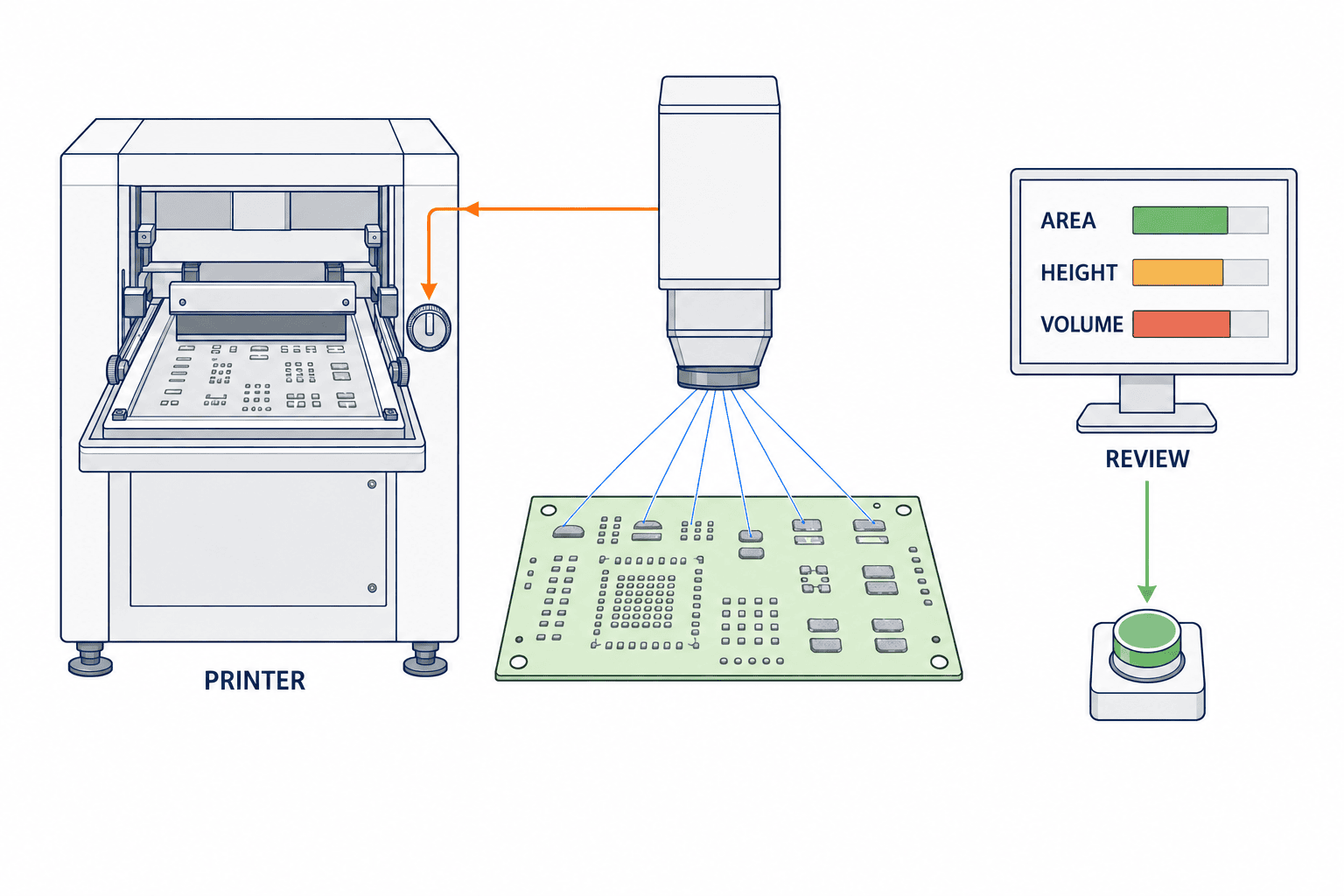
A typical route is board-ID read → paste printer → SPI → placer → reflow → AOI → AXI where needed. SPI sees paste deposits before parts obscure them. Depending on the equipment, it can assess area, height, volume, offset and bridging. Yamaha describes a YSi-SP implementation that combines 2D contour extraction with 3D height measurement and calculates volume; it also describes feedback for printer offset and cleaning. Those are capabilities of the stated compatible system, not a guarantee for every mixed-vendor line. Optical method, shadow handling, board-warp compensation, coverage and output granularity all need a demonstration with your own boards.
IPC-7527 supports visual acceptance assessment of solder paste printing. Its published scope distinguishes printed-paste appearance from paste-material evaluation under J-STD-005 and stencil design under IPC-7525. It explicitly says designed volume cannot be visually inspected. An RFP line reading only “IPC compliant” therefore cannot supply a universal 3D volume threshold. Agree product- and pad-group-specific measurement and disposition rules with the customer and validate them on the line. A single plant-wide percentage can miss critical features or reject good boards.
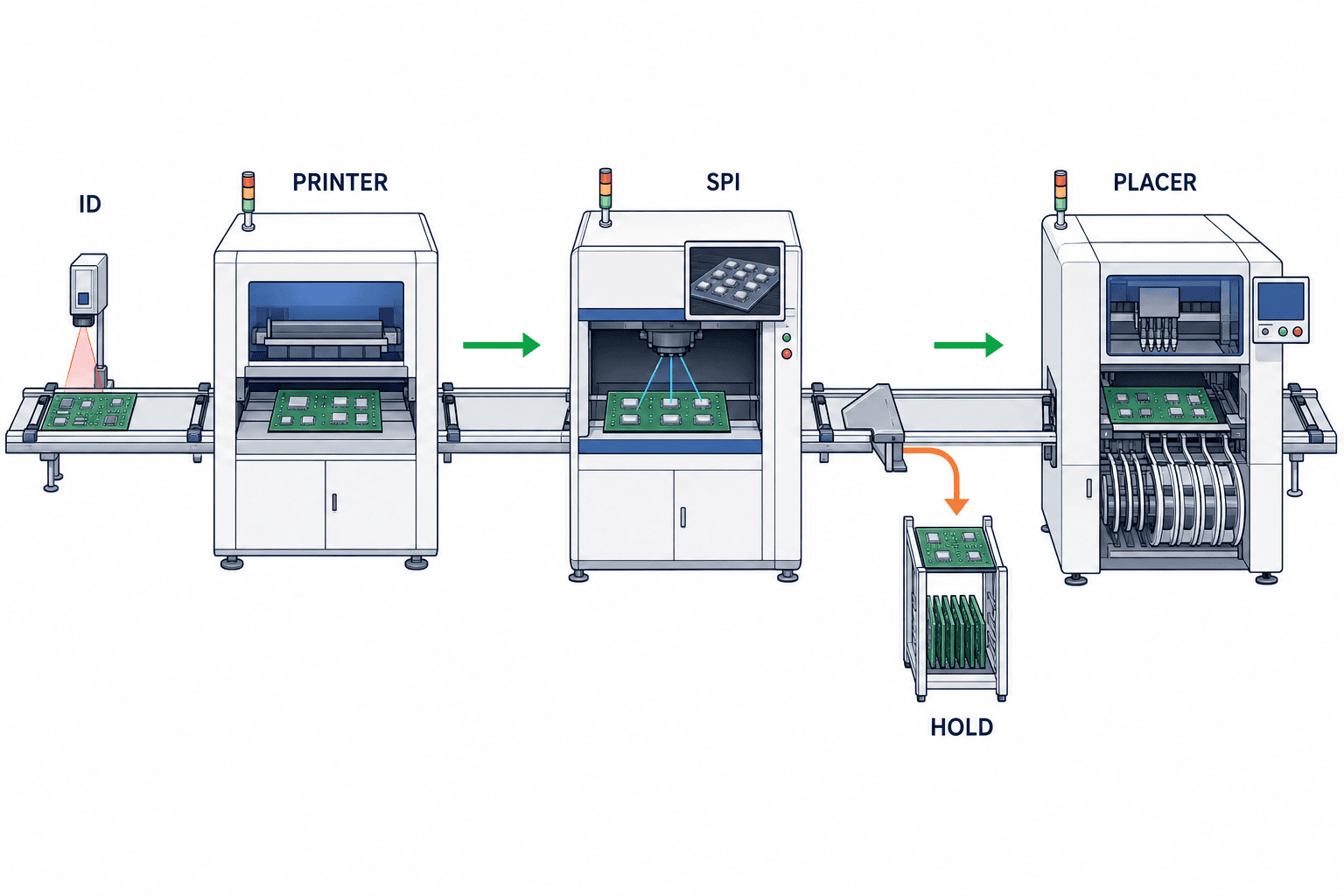
The first diagram shows verification of the previously read board ID at print exit, SPI before placement, and separate routes for permitted and held boards. Decide who may review a reject and when a washed/reprinted board can return. A repeat pass must be linked to the earlier attempt; otherwise the history falsely suggests one flawless print.
Four boundaries to settle before buying
Defect boundary. Name the print failures to reduce: bridging, insufficient or excess deposit, missing area, displacement or local shape problems. Classify by pad geometry and product criticality. A print anomaly is a process signal, not automatic proof that a final solder joint has failed. Correlation with downstream defects needs testing.
Measurement boundary. Choose the unit of record: panel, board, pad or individual deposit. A board-level PASS/FAIL may suffice for a simple gate but is inadequate for pad-level trend analysis or a customer root-cause report. Link board ID, product and recipe revision, stencil ID, material lot and event time where they are needed. Uncaptured historical images cannot be reconstructed later.
Control boundary. Distinguish an alert, an operator-approved recommendation and an automatic printer action. ASMPT documents closed-loop control using its printer, Process Lens SPI and optimization software. For another combination, test the exact vendor, model, software release and interface. “Connectable” does not prove that offset, underside cleaning, stop commands and acknowledgements all work in both directions.
Responsibility boundary. Assign recipe creation to a named owner, pad-group acceptance to engineering, final disposition to quality, ID/time alignment to IT/OT, and threshold-change approval to the product owner. Record old and new limits, reason, approver and the first affected board. Allowing undocumented on-shift relaxation may make the dashboard look better while erasing audit evidence.
Compare SPI equipment on eight practical dimensions
| Dimension | Ask the supplier | Evidence to observe |
|---|---|---|
| Measurement | How are 2D contours and 3D height/volume acquired? How are warp, shadow and reflection handled? | Repeat readings and images of the same board |
| Board range | Limits for size, thickness, warp, panel and double-sided work? | Transport and full coverage of the hardest in-house board |
| Programming | CAD/Gerber input, pad groups, versioning and changeover time? | An operator creates a new recipe |
| Decision logic | Pad-group limits, masks, review and reject classes? | Mixed good and known-bad samples |
| Cycle time | Transfer, measurement, ID check, MES exchange and reject handling included? | Continuous run at target line rate |
| Printer interface | Which offset, cleaning and stop actions are supported? | Handshake with the actual printer |
| Data | Board ID, coordinates, values, judgement, images and recipe revision accessible? | Real CSV/API/event sample |
| Service | Local Thai spares, calibration, recovery and upgrade support? | Contract and recovery exercise |
Use the same test board, paste, stencil, print conditions and defect definition for every vendor. Compare coverage and image storage as well as nominal resolution. A faster measurement mode may alter repeatability; retaining fewer images may make troubleshooting harder. Record any change to the demonstration conditions.
Separate measurement repeatability from operational consistency
Measure the same board repeatedly to see the variation of height or volume for a particular pad. Then test a different question: whether reviewers classify the same images consistently across shifts, and whether a recipe gives stable decisions on another day. Decide whether the reference is designed pad volume or an approved-good population before using measurement-system analysis. Advertised accuracy alone cannot establish a stable product decision. Rotate device order in comparative tests so changing paste conditions do not systematically favor one supplier.
Count the entire cycle, not the camera exposure
A camera cycle can be shorter than printer takt while board transfer, ID lookup, recipe load, MES acknowledgement or reject routing still create a bottleneck. Test the board with the most deposits, the busiest changeover period and restart after a communication fault. State which raw measurements and images are retained; solving a speed problem by silently turning off evidence collection defeats later root-cause work.
Design the proof-of-concept sample before the demo
A frequently produced standard board alone hides the hardest conditions. Include fine-pitch pads, broad ground pads, board edges, a thin board prone to warp, center and edge cavities of a panel, and a product with many deposits. Treat BGA and small passive pads as separate groups. In a high-mix plant, frequent changeover is itself a test condition. Prepare approved-good samples alongside known incomplete deposits, bridges, deliberately shifted prints and samples before and after stencil cleaning. Quality should label the expected condition before vendors see the set. Quarantine deliberately defective samples so they cannot enter customer production.
Record why each sample was selected, board revision, stencil ID, paste type/lot, printer settings, room conditions and test order. Paste can change while suppliers take turns, creating an apparent machine difference that is really sample drift. Where possible, prepare multiple boards printed under the same conditions and rotate device order. Report mistakes by pad group rather than only an overall machine score. A machine with the highest total score can still miss the plant’s most critical product.
Use gauge R&R for a defined measurement, not as a shortcut verdict
Area, peak height, average height and volume have different variability. Repeatedly passing the same board through a machine measures instrument repeatability; measuring separately reprinted boards mixes in process variation. Keep these studies separate. If human review is part of the decision, randomize images and measure agreement across reviewers without showing the previous verdict. Set acceptable variability from pad geometry, product use, customer acceptance and actual process spread. The published IPC-7527 scope does not provide one universal SPI volume limit. Report missed defects and false calls separately, including the effort to review each false call. Check whether measurements near a decision boundary alternate between PASS and FAIL, because that instability can pressure operators to loosen limits.
Test printer and MES together on one board
After stand-alone measurement works, follow one board through printing, an SPI anomaly, review, an approved cleaning request to the printer, and the response of later boards. Search the same board ID in MES: can a reviewer reconstruct the original value, revised decision and corrective action? A machine screen may show success while MES receives only PASS/FAIL. Inject a network outage, a paused MES and a printer that rejects a cleaning request. Test the hold rule, queued replay and whether manual and automatic actions create duplicate records. End the PoC with a list of unmeasurable regions, pad groups requiring tuning, review workload, unresolved interface fields and products not yet tested. Include recipe ownership and backup format in handover. Record approval as a defined product and operating scope, rather than an unqualified machine purchase.
Turn paste-print quality management into a controlled feedback loop
The value of SPI is the ability to investigate how a measurement change relates to an upstream change, not simply the number of red cells on a screen. A gradual shift in pad volume or offset may lead the team to check stencil contamination, alignment, paste condition and cleaning. A localized missing deposit may point to an aperture, support, board warp or cleaning issue. SPI data does not prove the cause alone. Align it by time with printer logs, paste and stencil IDs, ambient conditions and maintenance records.
For a first deployment, observe alerts and require a person to approve printer actions. Automate only actions whose benefit and side effects have been demonstrated. Automatic offset adjustment needs a limit, maximum repeated corrections and a stop on persistent same-direction drift. Decide what a lost connection does: retain the last setting, revert to manual or stop. The appropriate fail-safe behavior depends on product risk and line design, and belongs in SAT.
Avoid a generic “halve defects” claim. A before/after comparison needs the same defect definitions, product mix and follow-up method. Track print-related defect frequency, SPI detection and false-call rates, review time, printer downtime and downstream related defects. Agree the observation period and included products before a pilot; a small-lot fluctuation is not proof of improvement.
Define the SPI-to-MES data contract
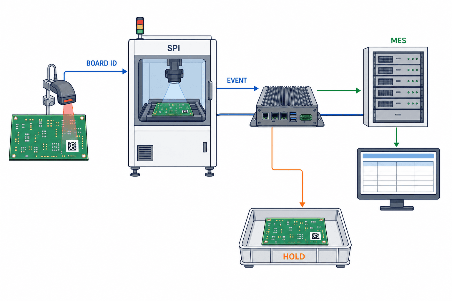
“Send inspection results” is not a workable interface specification. Set the board identity and event semantics first. A panelized line may need parent panel ID, cavity position and child-board ID. If the label cannot be applied before printing, a temporary fixture or transport identity must be mapped to the final ID under a documented exception rule. Handle unread labels, duplicate scans, manual re-entry, scrap and reprinting. The system must show which inspection event represents the final disposition without deleting the earlier attempt.
| Field | Meaning to agree |
|---|---|
| board_id / panel_id | Uniqueness scope, characters, reuse and missing IDs |
| product_code / revision | The design change and recipe revision applicable to this board |
| event_time / receive_time | Equipment time versus MES receipt; synchronization and time zone |
| machine_id / recipe_revision | Equipment and approved program in force |
| inspection_result | Exact meanings of PASS, FAIL, REVIEW, ERROR and BYPASS |
| pad_id / xy / measured_value | Coordinate system, unit, calculation and excluded pads |
| limit_version | Acceptance limits used at the time of decision |
| image_reference | Original-image location, retention and access rights |
MES need not contain every raw pad image. A practical design can store originals on an equipment/image server while MES receives board disposition, a measurement summary and a stable image reference. Document source of truth, retention, backup and deletion. Specify queue capacity during network loss, replay order, duplicate-event key and clock-skew checks. If an ACK is lost, a retry must not create a second board; if a human reclassifies the board, that new decision must not be discarded as a duplicate.
Interfaces may be file exports, vendor APIs or line-management software. A named industry standard or protocol does not show that the purchased model exposes every needed field. Ask for a sample payload, data dictionary, send trigger, error codes and a test environment. Decide whether a review overwrites an earlier result or creates another event; the latter preserves the chain of decisions more clearly.
For broader scheduling, BOM and changeover requirements, see our electronics and EMS production management guide. For the broader genealogy of reels, lots and individual boards, see electronics traceability design. This article deals specifically with the post-print inspection event.
IPC-2591 Connected Factory Exchange (CFX) provides a framework for exchanging information among equipment, processes and host systems. A “CFX-ready” label does not prove that this purchased model and option set exports every field above. Verify implemented messages and fields against sample data.
For the next process stage, see reflow temperature-profile management; for visible post-solder inspection, see AI-supported solder-joint inspection. Keeping the print, thermal and joint-inspection decisions separate prevents overlapping specifications.
Twelve questions for a useful SPI RFP
Ask each bidder to mark every response standard, paid option, custom work or unsupported, with a live screen, log or data sample where possible.
- Which areas of our smallest, largest, warped and panelized boards cannot be measured?
- How are area, height, volume, offset and bridges measured, calculated and expressed in units?
- How are unstable pad readings identified, calibrated or excluded?
- How long does first-article recipe creation, CAD/Gerber import, changeover and approval take?
- Can limits vary by pad group, with restricted review, hold and override permissions?
- With our printer model and software release, which offsets, cleaning and stop commands work both ways?
- What correction limits, communication-failure behavior and wrong-recipe protection are provided?
- Can real board, cavity, time, recipe, decision, measured value and image-reference data be exported?
- How are delayed, missing or duplicated MES events detected, replayed and reconciled?
- What capacity, retention, backup, search and export costs apply to images and raw data?
- Who in Thailand installs, calibrates, trains, services and supplies spare parts, and in which languages?
- What sample boards, known defects, evidence and unresolved-issue procedure does the FAT/SAT plan include?
Quote equipment, conveyors, readers, printer interface licenses, MES connection, image storage, commissioning, training, service and spares separately. A low purchase price can hide recurring recipe support or storage charges. Use the same cost categories and your actual product-change frequency to compare proposals.
FAT and SAT: test failures and recovery, not just a good board
FAT tests core behavior in the supplier’s controlled environment. SAT repeats the needed functions on the Thai plant’s actual printer, network, MES, shift pattern and products. Record precondition, input, expected result, actual result, log location, owner and retest date. Do not replace a failed test with a new pass without preserving what changed.
| Test | FAT | SAT |
|---|---|---|
| Known good/bad boards | Measure agreed samples and classification | Continuous run and review on live print conditions |
| Recipe revision | Wrong-version alarm, approval and rollback | Real changeover and first-article sign-off |
| Identification | Inject unread, duplicate and wrong-cavity IDs | Use actual scanner and transport exceptions |
| Printer feedback | Simulate limits, stops, cleaning and link loss | Exercise only approved actions on actual printer |
| MES events | Send normal, duplicate, delayed and replayed events | Reconcile counts and missing records in live MES |
| Images and logs | Search/export by board ID | Restore and search with plant user rights |
| Recovery | Power/application restart and low-disk condition | Restart across shifts and settle in-flight boards |
Set thresholds from product design, customer risk and baseline process capability, not a brochure. A “three days without stoppage” rule is weak if only a few boards are produced. If not all high-mix products fit a short SAT, agree representative products and conditional follow-up. Define board count, pad groups, defect sample types, allowed missing data and retest rules before sign-off.
Eight exceptions that deserve explicit test scripts
Reprinted board. Preserve the first FAIL and add a second print/inspection event after cleaning. A final PASS alone hides how often the board was reworked. Agree allowed re-entry with the customer.
Wrong board ID. Inject a label-read failure, another panel’s ID and manual entry. An unidentifiable board should be held for an authorized correction, not recorded as a provisional PASS.
Changed pad group. Use a design revision whose apertures or pad shapes differ while the old recipe is selected. Require a version mismatch alarm and first-article approval before release.
Duplicate transmission. Drop the MES ACK and replay an SPI event. Deduplicate on event ID while retaining a genuinely new review event. Reconcile board and event counts after recovery.
Runaway correction. Simulate repeated offset errors in one direction. The automatic adjustment must hit its approved limit and demand investigation. Validate this only for the actual printer/software combination.
Masked region. Verify that excluded pads are visible as excluded, not silently accepted. Reapprove masks after a design change.
Clock mismatch. Cross midnight on a night shift with equipment and MES clocks out of step. Keep both event and receipt time, monitor drift, and do not use timestamp alone as the unique join key.
Review across shifts. One shift holds a board and another reclassifies it. Preserve who decided, why, the image and before/after states, with role-based permissions.
KPIs and a staged rollout
Do not use the SPI reject percentage alone as the success measure; it can rise initially because of false calls. Trace print anomaly → detection → disposition → downstream outcome on the same board. Candidate measures are print-related defects per defined unit, false and missed calls, reprint frequency, printer stop/cleaning time, recipe changeover time, downstream related defects and evidence-retrieval time. Specify the denominator—boards, panels, deposits or shifts—before comparing products with very different pad counts.
A controlled rollout proceeds through priority products and defects, comparison on common samples, stable manual review and alerts, MES identity/result connection, then carefully tested automatic printer feedback. Gate each stage with agreed evidence and open issues. Starting all lines at once can overwhelm recipe creation and training while obscuring which change improved the outcome. Build exception and maintenance procedures on one line before expansion.
In Thailand, bring production engineering, quality, procurement and IT/OT into the RFP review together. Confirm local service language, spare availability, network ownership and customer approval early. Buying the camera first and specifying the data connection later can reveal that critical exports or licenses were optional.
Frequently asked questions
Does SPI replace AOI or AXI?
No. SPI measures paste before placement. AOI commonly inspects visible post-assembly conditions; AXI uses X-rays where joints are hidden. Combine them according to board design and customer requirements, and correlate results by board ID to refine print limits.
Should we choose 2D or 3D SPI?
2D may suffice for area and position checks. If controlling height or volume variation and printer feedback matters, evaluate 3D. Test shadow, reflection, board warp, takt and maintenance with your own samples. “3D always raises yield” is not a valid general claim.
Can SPI come before MES?
Yes, provided the contract preserves export of board identity, recipe revision, measurements, decisions and image references. Confirm file/API format and licenses now, and specify temporary storage and backup. Otherwise a future integration may be costly or lose historical evidence.
What should we bring to an initial discussion?
Bring the line flow, printer model/software release, board sizes and warp, product count, representative good and bad boards, takt, ID scheme, defect categories and current MES status. An explicit list of unknowns is also useful: it shows which assumptions must be fixed before pricing.
Discuss SPI implementation and MES integration in Thailand
TOMAS TECH supports the connection of equipment, production data and business systems at Thai manufacturing sites. Before choosing a machine, put the target defects, board identity, printer feedback, MES evidence and FAT/SAT acceptance rules on one page. Share the number of lines, printer model, MES status and defect concern through our contact form to start with the right scope.
Sources and limits of this guide
- IPC-7525C, Stencil Design Guidelines: the published scope notes that printing depends on many variables and no single design-rule set applies.
- IPC-2591 Connected Factory Exchange: information exchange among equipment, processes and hosts; verify each product implementation.
- IPC-7527, Requirements for Solder Paste Printing: published scope for visual print acceptability and boundaries against paste-material and stencil-design documents.
- IPC J-STD-005A, Requirements for Soldering Pastes: scope of paste-material characterization; check IPC’s revision table for the current revision.
- IPC document revision table: distinguishes IPC-7525, IPC-7527 and J-STD-005 and lists revisions.
- Yamaha Motor YSi-SP features: one product example of contour, height, volume, warp handling and compatible printer feedback.
- ASMPT Process Lens: vendor description of post-print SPI process feedback.
- ASMPT on closed-loop print control: example using its printer, SPI and optimization software; validate applicability on your line.
This guide uses publicly accessible material, not paid standards text or a customer’s acceptance specification. Confirm final limits, inter-machine communication and retention for the specific product and contract.


