



Introduction: Decide How to Light the Part and How to Judge It Before Choosing the AI
Inspectors check every sealing surface, sliding surface and plated finish by eye. The same scratch is passed by one person and rejected by another. You once installed rule-based machine vision, but gloss and machining marks kept causing over-detection, and the line went back to visual checks. Now the head office in Japan or your customer is asking for “AI visual inspection.” This article is for Japanese-affiliated factories in Thailand that are considering metal surface defect inspection AI in exactly this situation.
The target readers work at automotive parts, motorcycle parts and metalworking (machining, stamping, die casting, plating) plants in Chonburi, Rayong, Ayutthaya, Prachinburi and similar areas. We have quality assurance, production engineering and plant managers in mind.
Here is the conclusion first. Whether metal surface defect inspection AI succeeds is largely decided by the following two points, even before the choice of AI model.
- How to light the part (imaging method): whether to diffuse the light, use specular reflection, create shadows from multiple directions, or look at distortions in reflected patterns
- How to judge it (boundary samples): which defects, on which surface, become rejects from what size
On metal, halation caused by gloss and surface textures such as cast skin and machining marks make the judgment rules complicated. On near-mirror surfaces, inspection methods that assume diffuse reflection cannot be used as they are. Once imaging and criteria are settled, you choose the AI approach. At sites with few defect samples, start with anomaly detection trained only on good parts. When you reach the stage of recording defects by type and linking them to countermeasures, add supervised learning with labeled defects. There are also cases that combine both.
Acceptance criteria are not decided by metrics from research papers. For each of your own parts and defect types, count “misses (judging a defect as good)” and “over-detections (judging a good part as defective)” separately. Also define the procedure for sending images that are hard to judge (gray judgments) back to people. Set the tolerance for misses more strictly than the tolerance for over-detection. This applies especially to safety-critical parts. Make it a requirement that judgment results are stored together with the image, lot and equipment conditions, and passed on to quality data and traceability.
This article is not a recommendation or ranking of specific products. Product functions and figures are introduced as the manufacturers’ descriptions. The cost-benefit section later is a model calculation built on hypothetical numbers for this article. General procedures, including lighting, cameras and annotation, are covered in our AI visual inspection implementation guide. This article focuses on scratches, dents, porosity and chipping on metal surfaces.
Why Metal Parts Plants in Thailand Are Reviewing Visual Inspection Now
First, let us check the current state of Thai manufacturing and the automotive industry. Figures are given with their source and scope as published. We do not add them together or apply them to any individual company.
- Vehicle production is above last year, but the full-year outlook was cut: According to a Reuters report, vehicle production in August 2026 announced by the Federation of Thai Industries (FTI) was 124,646 units, up 10.93% year on year. In the same month of August, exports were down 2.04% year on year. The FTI has revised its full-year 2026 production outlook down to a 3.33% decline from the previous year, citing lower exports due to the conflict in the Middle East
- Industrial output grew: According to a Reuters report carried by The Star, the Manufacturing Production Index (MPI) for August 2026 announced by the Office of Industrial Economics of the Thai Ministry of Industry was up 4.44% year on year
- Orders and output expanded, while employment fell through natural attrition: The S&P Global Thailand Manufacturing PMI reported by Trading Economics was 54.3 in September 2026. The same release said employment edged lower, with firms citing natural attrition
- Business sentiment is weak, and demand for automotive parts is unsteady: According to Trading Economics data, Thailand’s business sentiment index was 48.1 in September 2026. The same article said that in the automotive sector, rising EV imports reduced demand for domestically produced parts
- Investment applications for automation: According to the Thailand Board of Investment (BOI) press release of July 23, 2026, among investment promotion applications filed in January to June 2026, the automotive sector accounted for 122 projects worth USD 759.2 million. Applications under the “Smart and Sustainable Industry” measure (machinery upgrades, adoption of digital technology, integration of automation and robotics) numbered 132, worth USD 507.6 million. Both figures are based on applications, not approvals
Orders and output are recovering, yet headcount is slowly shrinking through natural attrition. For automotive parts, both exports and demand for domestically produced parts are unsteady. In this environment, it becomes harder to keep supporting visual inspection of every part with headcount alone. In addition, the more demand fluctuates, the more strictly customers watch quality stability. Reviewing visual inspection is not only about saving labor. It is also about reducing variation in judgments and keeping inspection results as records.
Metal Surface Defects and Why They Are Hard to Inspect
There are several typical surface defects on metal parts. The following is a general editorial overview.
| Defect | Main source process | Visual characteristics |
|---|---|---|
| Scratches (scuffs, line scratches) | Machining, handling, assembly | Thin and long. Visibility changes with orientation |
| Dents | Handling, stamping, dropping | Shallow depressions. Hard to see from straight on |
| Porosity (casting voids, pinholes) | Die casting, casting | Small holes. Easily confused with the cast skin pattern |
| Chipping, burrs | Machining, stamping, trimming | Irregular edge shape |
| Press marks, galling | Stamping, press-fitting | Part of the surface reflects light differently |
| Plating unevenness, stains | Plating, washing | Uneven color tone or gloss. Hard to distinguish from scratches |
Why are metal surfaces difficult? A report by the Hyogo Prefectural Institute of Technology points out, for metal parts, that halation caused by surface gloss and the influence of surface textures such as cast skin and machining marks make the judgment criteria complicated, so that setting, managing and revising rules becomes cumbersome. The experience of earlier rule-based inspection stalling because of over-detection closely matches this description.
Near-mirror surfaces bring a different difficulty. A Fraunhofer IOSB document explains that surfaces where specular reflection matters pose special challenges for inspection, and that many established surface inspection methods rely on diffuse reflection, so they cannot be used as they are to evaluate specular surfaces. On polished sliding surfaces, ground surfaces and bright plated surfaces, depending on how the light is applied, scratches can disappear, or things that are not scratches can look like scratches.
Here we draw two lines. The first is dimensions. Pass/fail judgments for hole diameters, flatness, step heights and so on are handled by a measurement system separate from surface scratches. Dimensional automation is covered in our article on dimensional inspection automation. The second is material. Plastic molded parts have different defect types, such as sink marks, short shots and weld lines, and reflect light differently. For plastic molded parts, please see our article on AI visual inspection for injection-molded parts.
Choosing the Imaging Method: Diffuse, Specular, Multi-Direction and Deflectometry
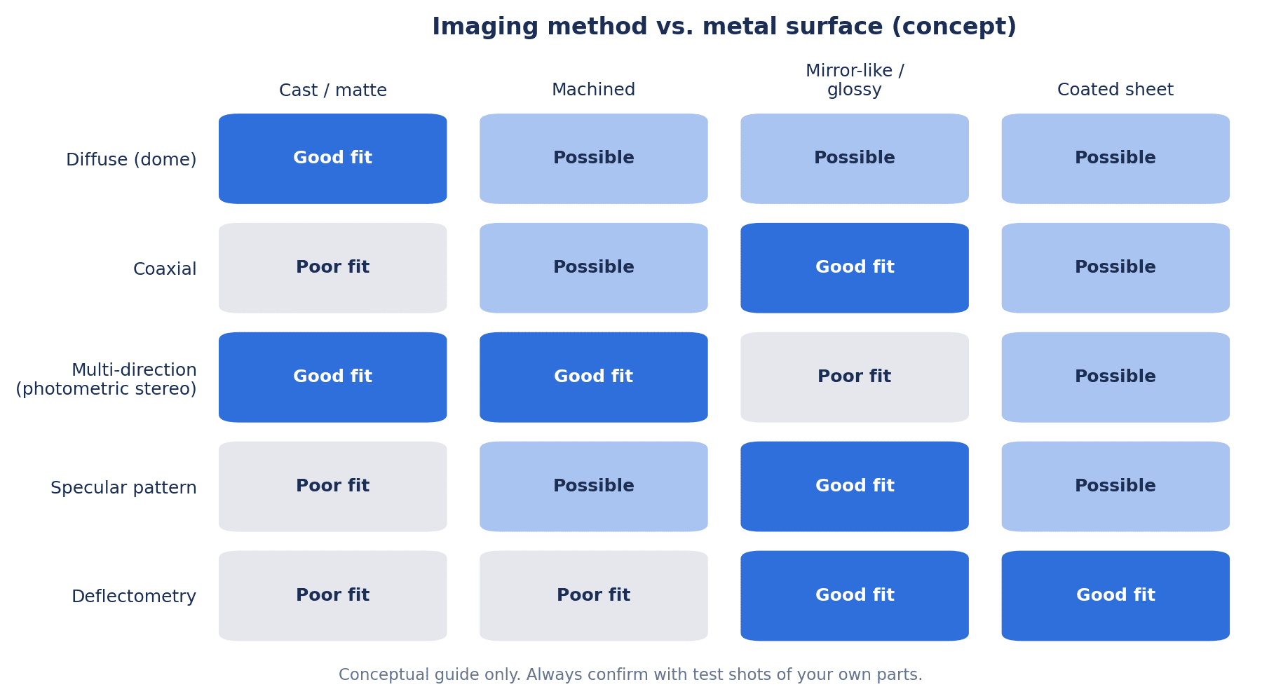
In metal surface scratch inspection, the imaging method is the first fork in the road. AI cannot find defects that do not appear in the image. Conversely, if imaging makes a defect clearly visible, it becomes easier for both AI and people to judge. We summarized the fit between surface properties and imaging methods in a conceptual diagram.
| Method | Defects that show up easily | Suitable surfaces | Cautions | Representative examples (per each company’s description) |
|---|---|---|---|---|
| Diffuse lighting (dome lighting, etc.) | Color unevenness, stains, dirt | Cast skin, matte finish, curved surfaces | Contrast of shallow scratches and dents may drop | General configuration (editorial description) |
| Coaxial lighting | Scratches on flat surfaces | Flat, near-mirror surfaces | May be weak on curved or tilted surfaces | General configuration (editorial description) |
| Multi-direction lighting with image analysis (photometric stereo type) | Shallow unevenness (scratches, dents) | Cast skin, machined surfaces, surfaces with markings | Requires multiple images. Assumptions tend to break down on strongly mirror-like surfaces | Keyence LumiTrax, MVTec HALCON operators |
| Imaging that uses specular reflection | Pinholes, unevenness, streaks, wear | Cylindrical metal surfaces, glossy surfaces | Requires a dedicated setup, such as synchronization with lighting patterns | Keyence LumiTrax specular reflection mode |
| Deflectometry | Shape irregularities that appear as distortions in reflections | Mirror-like surfaces such as painted metal sheets | Requires arrangement and calibration of the screen and camera | Fraunhofer IOSB document |
Here we keep the effects of dome and coaxial lighting at the level of general statements. Dome lighting is commonly used as a configuration that diffuses light to suppress specular glare, and coaxial lighting as a configuration that shows scratches on flat mirror surfaces as differences in brightness. However, whether they work depends on the shape and surface of the part. Compare them by imaging the actual parts.
On multi-direction lighting, Keyence describes its LumiTrax as follows. It synchronizes the CMOS sensor with the lighting direction at high speed, analyzes multiple images illuminated from different directions, and generates a “shape (unevenness) image” and a “texture (pattern) image.” As an example application, it cites emphasizing markings on a cast skin surface. The company also explains that creating shadows with directional lighting allows detection of defects in the height direction, and that it can remove glare from glossy objects.
On the specular reflection mode in the same family, Keyence explains that it synchronizes a striped, changing lighting pattern with the CMOS sensor and generates a normal image, a specular reflection image, a diffuse reflection image, a gloss ratio image and a shape image from a single capture. It shows examples of making pinholes, unevenness, streaks and wear visible on cylindrical metal surfaces such as bearings.
For photometric stereo as a technique, MVTec’s HALCON documentation lists the preconditions. At least 3 images of the same object with different lighting directions are needed, taken with a stationary camera. Fine surface features such as dents, wrinkles and scratches can be extracted. On the other hand, it usually cannot be used to measure the overall shape of an object. For best results, diffuse (Lambertian) reflection without inter-reflections or shadows is desirable. Because it assumes orthographic projection, a telecentric lens or a long-focal-length lens is required. In other words, multi-direction lighting is a method that brings out shallow unevenness, but on strongly mirror-like surfaces its assumptions break down if used as is. For mirror surfaces, there are other methods, such as imaging that uses specular reflection and deflectometry.
On deflectometry, the Fraunhofer IOSB document defines it as a general term for methods that obtain shape information of mirror surfaces by automatically analyzing the reflection of a known pattern. The document explains that it is particularly suited to inspecting painted metal sheets quickly and reliably. It does not necessarily apply as is to small surfaces on machined parts.
Types of lighting and how to proceed with their selection are covered in detail in our article on AI visual inspection lighting selection, and how to choose cameras and lenses in our article on industrial camera selection.
Imaging Curved, Cylindrical and Large Parts
For a flat surface, one camera and one lighting set may be enough. However, many metal parts are cylinders, stepped shafts, housing interiors or parts with multiple sealing surfaces. A single image from one direction makes it easy to miss defects.
Here are commonly used configurations, as an editorial overview.
- Rotate and capture: Rotate a cylindrical part and capture the circumference with a line scan camera or continuous shooting
- Capture from multiple viewpoints: Install multiple cameras, or flip the part, and capture each surface
- Move the imaging position with a robot: Have a robot hold the camera and lighting, and change the imaging position for each surface
Public documents also show examples of such configurations. The Fraunhofer IOSB document shows a configuration in which a large, complex-shaped part is divided into patches, and a sensor head combining a screen and a camera is moved by an industrial robot to inspect the entire surface. deevio’s case study page describes imaging the sealing surface of a throttle body from 3 directions using a robot, at a die-cast parts supplier in Germany.
As the number of surfaces to capture increases, the design of fixtures, robots and cycle time becomes heavier. First, narrow down the surfaces that need inspection using boundary samples, and decide which surface to capture from which direction. Not making full-surface capture the goal is a shortcut to keeping costs down.
AI Approach 1: Anomaly Detection Trained Only on Good Parts
In metal parts plants, defect samples are hard to collect. The lower the defect rate, the fewer defect images are available for training. This is where anomaly detection AI trained on good parts only comes in. It learns what “normal” looks like from good parts and flags images or regions that deviate from it as anomalies.
MVTec explains that for HALCON’s anomaly detection, the training data consists only of images without anomalies. The outputs are an Anomaly Score, which indicates how anomalous the whole image is, and an Anomaly Image, which indicates the degree of anomaly for each pixel. The company explains that in addition to structural anomalies such as scratches, cracks and dirt, Global Context Anomaly Detection also targets logical anomalies such as wrong counts or wrong positions.
LandingAI’s LandingLens documentation positions anomaly detection for “cases with few images of anomalies.” The training set consists only of Normal images, and the classes are fixed at two, Normal and Abnormal. The company’s documentation recommends 50 or more Normal images and at least 1 Abnormal image (ideally 10 or more) in the Dev set used for evaluation. This is a recommendation for the company’s product and does not mean that this number of images is enough for every part.
In research, a method called PatchCore is well known. The paper published in 2021 addresses the problem setting of building a model from good-part images only (the cold-start problem), and uses a memory bank that collects representative patch features of good parts. The paper reports image-level AUROC of up to 99.6% on the research dataset MVTec AD (15 categories). AUROC is a threshold-independent ranking metric, and this figure is a value on a research dataset. It is not a detection rate or miss rate in a factory.
MVTec AD is a research dataset consisting of 15 object and texture categories. According to the PatchCore paper, it contains 5,354 images in total, of which 1,725 are for testing. The categories include metal nut (metal_nut) and screw (screw). However, according to MVTec’s official page, the license is CC BY-NC-SA 4.0, and use for commercial purposes is not permitted. It can be used for research comparisons, but not as training data for your own inspection system.
The strength of anomaly detection is that training can start without any defect samples. On the other hand, there are two cautions. First, evaluation requires defect samples. The only way to count misses is to actually run defective parts through the system. Second, “anomaly” and “defect” are not the same. Variations in plating color tone, cast skin patterns and differences in the direction of machining marks will also be flagged as anomalies if they differ from the learned good parts. The key is how much acceptable variation you include in the good-part images.
AI Approach 2: Supervised Learning with Labeled Defects (Classification and Segmentation)
In supervised learning, you label defect images, such as “this is a scratch” or “this is a dent,” and train the model on them. Approaches include classification, which sorts images into good and defective; object detection, which encloses defect locations in boxes; and segmentation, which marks defect regions pixel by pixel.
A study by the Hyogo Prefectural Institute of Technology detects scratches on metal M6 nuts with a segmentation model based on U-Net with Residual Blocks built in. Under laboratory conditions, 70 good nuts and 50 defective nuts with intentional scratches were photographed, and the images were augmented by rotation and flipping for training. The judgment method rates a part NG when the area of the detected defect exceeds a threshold. The report contains no accuracy figures such as detection rates, and stays at a qualitative statement that scratches could be detected accurately.
A case study page of Germany’s deevio targets delamination, porosity, dents caused by delamination and press marks on aluminum die-cast throttle bodies. It is a supervised approach in which defect samples provided by the customer are photographed and the defects are marked jointly with the supplier for training.
The strength of supervised learning is that it can separate defect types. If you can count by type, such as “porosity increased” or “press marks increased,” it becomes easier to trace whether the cause lies in the die, the cutting tool or handling. The weakness is that each defect type requires enough images and labels. If labeling criteria differ from person to person, the AI will also waver. Labeling procedures and how to think about acceptance are covered in our article on annotation. As a way to compensate when defect samples are insufficient, the approach of synthetic data is summarized in our article on synthetic data for manufacturing.
Combining Approaches, and Using AI Alongside Rule-Based Inspection
Anomaly detection and supervised learning are not an either-or choice. There are cases that combine them.
According to the results report (FY2021) of a Shiga Prefecture subsidy program, Takahashi Kinzoku of Japan (Shiga Prefecture) developed an AI image inspection system for visual inspection of safety-critical automotive parts that combines a VAE trained on good parts with images from supervised training. The VAE produces a reconstructed good-part image, and scratch candidates are extracted from the difference with the original image. On top of this, the configuration passes a part only when all 3 AIs with different characteristics judge it OK. The report states that training on good samples rather than defect samples made it possible to train on a large number of samples and also improved judgment accuracy. At the same time, it adds that training on defect samples is also necessary.
What can be read from this configuration is the idea of “catching anomalies broadly with good parts, distinguishing type and degree with supervised learning, and issuing a pass conservatively.” It can be called a design suited to safety-critical parts, where misses are to be avoided.
There is also no need to discard rule-based image processing. Items that rules can judge stably, such as dimensions, positions and obvious chipping, can be left to rules. Keyence explains that its VS series can use AI tools (AI Segmentation, AI Detection, AI Classification, AI OCR) and rule-based tools such as Scratches on the same image. It is a good idea to decide, for each defect type, which items to leave to AI and which to judge by rules.
Examples of Products and Services
Below are examples of products and services relevant to metal surface inspection. All are manufacturers’ descriptions, not recommendations or rankings.
| Product or service | Approach (per each company’s description) | Images used for training (per each company’s description) | Public pricing |
|---|---|---|---|
| Keyence LumiTrax | Multi-direction lighting with image analysis, specular reflection mode | Not applicable, as it is an imaging method | Could not be confirmed |
| Keyence VS series | AI tools and rule-based tools used together on the same image | Training with a general-purpose PC and dozens of images | Could not be confirmed |
| MVTec HALCON | Anomaly detection, Global Context Anomaly Detection, photometric stereo operators | Good-part images only for anomaly detection | Could not be confirmed |
| Omron FH series (announced 2020) | Defect detection AI that reproduces the skills of experienced inspectors, AI Fine Matching | No training samples needed for defect detection AI; good-part images for AI Fine Matching | Could not be confirmed |
| LandingAI LandingLens | Object detection, classification, segmentation, anomaly detection | Normal images only for anomaly detection | Partly available (see below) |
| Basler Pylon AI Platform | MLOps web application that optimizes AI models and compares performance on various processors | Not applicable | Listed by a distributor (see below) |
In a European announcement on September 1, 2020, Omron explained that the FH series is equipped with defect detection AI that reproduces the skills of experienced inspectors and can detect scratches and stains without training samples or adjustment. It also states that AI Fine Matching learns from good-part image data, memorizes acceptable variation and reduces over-detection. Because this is a 2020 announcement, the current lineup needs to be checked individually.
Few products publish their prices. According to LandingLens’s “Plans” documentation (as viewed in October 2026), the Free plan is USD 0 with 1,000 credits per month (no overage), and downloading active projects is limited to Noncommercial Use. Enterprise is quoted individually (Contact sales). It is natural to assume that production use in a factory would require an individually quoted contract rather than the free tier. The Basler Pylon AI Platform is listed by distributor Graftek (as viewed in October 2026) at USD 8,000 for a license covering 5 users for 365 days. This is the price of an MLOps web application, not the price of the inspection software itself. We could not confirm public pricing for Keyence, MVTec HALCON or Omron.
Cognex is also named as a representative vendor. In Japan, there are also companies such as COSM that offer solutions combining in-house developed AI models with cameras.
What the Case Studies Tell Us
Here we organize the published case studies together with their scope.
Takahashi Kinzoku (Japan, Shiga Prefecture): This is the FY2021 subsidy results report of one company that had been shipping safety-critical automotive parts after visually inspecting every one of them. The challenges were that variations in plating color tone kept the old AI’s judgment accuracy from improving, scratches did not appear clearly, and preparing large numbers of defect samples was difficult. According to the results table in the report, the new AI made 0 misjudgments among 1,500 good parts (0.0%), judged 70 of 1,500 defective parts as good (4.6%), and had an accuracy rate of 97.7%. The old AI’s accuracy rate was 80.3%. The report states that the VAE training period was extended to 3 months. While misjudgments of good parts as defective were eliminated, the miss side, judging defects as good, fell short of the target and is described as not achieved.
Hyogo Prefectural Institute of Technology (Japan): A study of one type of M6 nut, with 70 good and 50 defective parts, under laboratory conditions. Training was done on a PC with a GPU, and the study showed that inference also runs on a small PC without a GPU. No accuracy figures are reported.
Ito Kinzoku Kogyo (Japan, Aichi Prefecture) and COSM: According to an ASCII.jp article dated February 14, 2025, the target is a bolt union, a fitting that connects an engine and a pipe. The challenges before introduction were cited as the burden of visual inspection caused by excessive detection, aging inspection equipment used for about 15 years, and an increase in gray zones as defect judgment criteria became stricter. What is being introduced is “COSM AI VISION,” which combines in-house developed AI models, high-resolution cameras, polarization cameras, infrared sensors and more. The effects are described as “expected effects,” aiming to improve inspection accuracy and consolidate inspection machines, and there are no actual result figures.
A die-cast parts supplier in Germany (anonymous) and deevio: A case in which the sealing surface of a throttle body is captured from 3 directions with a robot. The customer’s development engineer stated, in effect, that the AI was able to detect defects that conventional image processing could not. No figures are given.
Three points can be read from these. First, “variations in gloss and color tone,” “excessive detection” and “gray zones” appear repeatedly as starting points. Second, there are cases that combine good-part learning with supervised learning, and there are products that can use AI and rule-based tools together. Third, the figures in published cases come from one specific company or from laboratory conditions. They should not be assumed to apply as is to your own parts. Note also that in this research, we did not find any published case of surface inspection AI for metal parts at a site in Thailand where the company name, part and conditions could be confirmed.
Fix Boundary Samples and Inspection Criteria Before the AI
An AI’s pass/fail mirrors the criteria it was trained on. If human criteria are vague, the AI’s judgments will also be vague. J-Net21 of the Organization for Small and Medium Enterprises and Regional Innovation, Japan (SMRJ) explains that sensory inspection (a method of judging quality with the human senses) evaluates things such as plating gloss, color tone and surface scratches by feel, and that judgments vary depending on the inspector and the inspection environment. As key points for improving accuracy, it cites preparing boundary samples, preparing the inspection environment such as lighting brightness and direction, and standardization through unified procedures and training. This applies just as well before introducing AI.
For boundary samples, write the pass/fail criteria for each defect type using the following items.
- Size: from what length, width or diameter a defect becomes a reject
- Depth and height: whether it is a step you can feel with a finger, or something visible only under certain lighting
- Location: whether it is on a functional surface such as a sealing surface, sliding surface or fitting area, or on a non-functional surface not visible from outside
- Number and density: for example, one small pore is acceptable, but a cluster is not
- Viewing conditions: lighting, angle, distance and viewing time
Also decide how to handle gray zones. Will an image that looks “about the same as the boundary sample” be passed, or sent for human re-judgment? If there are criteria agreed with the customer, use them as the starting point. Review old boundary samples to see whether they still match current products. If you photograph the boundary samples and keep the images together with the lighting conditions, they can later serve as evaluation data for the AI as well.
IATF 16949, the quality management standard for the automotive industry, also requires control of evaluation conditions for appearance items. When replacing visual inspection with AI, it is important to keep evaluation conditions and judgment records in a form that can be explained in audits. Evidence design is covered in our article on IATF 16949 traceability.
Setting Acceptance Criteria: Count Misses and Over-Detections Separately
If you set the acceptance criteria for a PoC or acceptance test as a single number such as “accuracy of X%,” you will misjudge. This is because visual inspection errors come in 2 types with different natures.
- Miss: judging a defect as good. Defects flow out and lead to customer complaints
- Over-detection: judging a good part as defective. Human re-inspection and scrapping of good parts increase
The Takahashi Kinzoku report mentioned above is an example that shows this difference well. In the FY2021 subsidy program results report by one company in Japan (Shiga Prefecture) on safety-critical automotive parts, the accuracy rate was 97.7%, but the breakdown was 0 misjudgments on the good side (0.0%) and 70 misses out of 1,500 on the defective side (4.6%). In the same report, the accuracy rate reached its target, while the miss side did not reach its target. It is a result for one company and one type of part, but it shows why acceptance criteria should be split in two.
We made a conceptual diagram of the judgment flow.

The AI outputs an anomaly score or defect type for each image. If the score is clearly low, the part is OK; if clearly high, NG; anything in between is gray and is re-judged by a person. NG parts are recorded with their image and lot and passed on to quality data. Moving the threshold creates a trade-off between misses and over-detections. Trying to reduce misses increases over-detections and gray judgments, which increases human re-judgment workload.
The PoC evaluation table takes the following form. Target values are for your company to decide, and the table is only an example.
| Metric | Definition | Evaluation data | How to judge |
|---|---|---|---|
| Miss count | Number of defects judged as good (per defect type) | Actual defective parts and the reject side of boundary samples | Set most strictly. Especially for safety-critical parts |
| Over-detection rate | Share of good parts judged defective or gray | Good parts from normal production | Decide the acceptable range based on re-judgment workload |
| Gray rate | Share sent for human re-judgment | All parts from normal production | Whether it fits within re-judgment staffing and time |
| Repeatability | Agreement of judgments when the same part is run repeatedly | Selected good and defective parts | Whether judgments waver |
| Processing time | Time from imaging to judgment per part | Normal production | Whether it fits within the line cycle time |
Set the tolerance for misses more strictly than for over-detection. This is because misses lead to outflow, while over-detection often only increases workload. Write the procedure for sending gray judgments back to people as part of the acceptance criteria. How to set thresholds and how to reduce over-detection are covered in detail in our article on reducing false rejects in AI visual inspection.
Collecting and Managing Training Data: Changes in Lighting, Part Lots and Process Conditions
Whether you use good-part anomaly detection or supervised learning, bias in the training data becomes bias in judgments. Do not collect good-part images from only one lot on one day. Collect them so that they include differences such as the following.
- Part lots and materials: raw material lots, plating lots
- Dies, cutting tools, fixtures: die numbers, before and after tool changes, fixture differences
- Process conditions: cutting conditions, die casting conditions, plating bath condition
- Time of day and season: ambient light, temperature, how much oil or cutting fluid remains
- Imaging conditions: aging of lighting, dirt on the camera, deviations in part placement
Build a mechanism for saving defect images each time they occur, together with their boundary sample category. Keep defect samples for evaluation separate from those used for training.
When conditions change, AI judgments change too. Die renewals, changes of cutting tool manufacturer, changes in plating conditions, and replacement of lighting or cameras should all trigger re-evaluation. The FY2021 subsidy results report by Takahashi Kinzoku of Japan (Shiga Prefecture) also states that the VAE training period was extended to 3 months for safety-critical automotive parts, which suggests that it takes time to teach the model the variation in good parts.
After going live, monitor the distribution of anomaly scores and trends in the gray rate. A sudden rise in the gray rate may be a sign that something in the parts or the imaging has changed. Approaches to monitoring, retraining and rollback are summarized in our article on factory AI model monitoring.
System Architecture: Edge PCs, Line Integration and Data Storage
Because metal surface scratch inspection must be judged within the line cycle time, inference is in many cases run on a PC placed near the line.
The study by the Hyogo Prefectural Institute of Technology shows an example of inference running even on a terminal without a GPU. Under laboratory conditions with M6 nuts, training was done on a PC with a GPU (RTX 3090), and inference on the LattePanda V1, a small PC with an Atom x5-Z8350. Inference time per image was reported as 3.56 seconds with NNabla and 0.38 seconds with OpenVINO. On a desktop PC (Core i5-12500) it was 0.02 seconds with OpenVINO, and on a laptop PC (Core i3-1115G4) 0.06 seconds. These are values for a single part and a single model, so whether it fits within your own cycle time has to be checked with actual parts. The same report also states that high license fees for commercial deep learning software and equipment costs for high-performance GPU-equipped PCs are obstacles to adoption.
Here are the items to check when deciding the architecture.
- Line integration: signal exchange with the PLC, ejection of NG parts, conditions for stopping the line
- Inference PC: with or without GPU, industrial PC or general PC, spare unit and replacement procedure
- Image storage: whether to store all images or only NG and gray ones. Your company decides the retention period and capacity
- Network: whether images are sent to an on-site server or to the cloud, and whether this complies with customer contracts and internal rules
- Model updates: who installs a new model, by what procedure, on which PC
Deployment of AI at the edge and how to proceed with acceptance are covered in our edge AI factory deployment guide.
Linking Judgment Results to Quality Data and Traceability
Ending an AI judgment at “OK or NG” is a wasted opportunity. Metal surface defects have process causes. Porosity is related to die casting conditions and die condition, line scratches to handling and fixtures, and press marks to stamping conditions. Linking judgment results with process data makes causes easier to trace.
At a minimum, link and store the following items.
- Part identification (serial, lot, marking)
- Date and time of imaging, line, equipment, imaging conditions
- The image, and the AI’s score and judgment (defect type, location)
- Results of human re-judgment and who made the judgment
- Process conditions (die number, cutting tool, shot, plating lot, etc.)
Results of human re-judgment are especially important. Images on which the AI and people disagreed become material for the next round of training and for revising boundary samples.
How to hold quality data so that it leads to identifying causes is covered in our article on quality data management systems and our article on defect root cause identification systems. If you want to trace porosity or cast skin defects on die-cast parts back to the shot level, our article on die casting traceability is a useful reference. Disposition of NG parts and recording of reason codes are covered in our article on scrap management systems.
Requirements to Write in the RFP and FAT/SAT Acceptance Criteria
When outsourcing metal surface defect inspection AI, write the following items in the RFP (request for proposal). Numerical targets are for your company to decide, and the table is only an example.
| Item | What to write in the RFP |
|---|---|
| Scope | Parts, surfaces (sealing surfaces, sliding surfaces, etc.), defect types and boundary samples |
| Cycle time | Allowable time per part, line speed |
| Imaging method and lighting | Range of proposals requested (diffuse, specular, multi-direction, multiple viewpoints, robot) and execution of tests with actual parts |
| Learning approach | Proposals for good-part anomaly detection, supervised learning, a combination, or use alongside rule-based tools |
| Evaluation data | Numbers of good and defective parts, collection period, range of lots and dies |
| Acceptance criteria | Miss count, over-detection rate and gray rate per defect type |
| Gray judgments | Procedure for sending back to people, display method, records of re-judgment |
| Image storage | What to store, retention period, capacity, search method |
| MES integration | Method of passing part identification, judgments and image references |
| Retraining | Procedure, who decides to carry it out, cost classification (included in maintenance or charged separately) |
| Training and maintenance | Training for operators and maintenance staff, response time for failures, spare parts |
| Quotation breakdown | Hardware (cameras, lighting, fixtures, PCs), software licenses, training and tuning work, maintenance |
Asking for the quotation to be split into these 4 parts makes comparison easier. Hardware is a one-time investment, but licenses and maintenance recur every year. Training and tuning work arises each time the number of target parts or defect types increases.
Acceptance testing is done in 2 stages.
- FAT (factory acceptance test before shipment): On the vendor’s side, reproduce the judgments using your own past boundary samples and actual defect samples. Check, for each defect type, whether the acceptance criteria in the RFP are met
- SAT (site acceptance test): On your own line, run the system in parallel with visual inspection and cross-check the judgments. Count misses, over-detections and gray judgments for each defect type. Include changeovers of lots, dies and cutting tools in the parallel-run period
If a miss is found in the SAT, compare the image of that defect with the boundary samples and isolate whether it is an imaging problem, a learning problem or a criteria problem.
Cost and Benefit Model Calculation (Hypothetical Numbers)
From here on is a model calculation built on hypothetical numbers for this article. These are not actual product prices or labor hours. Because official prices for many products could not be confirmed, all costs are placeholders.
The assumed plant is a Japanese-affiliated automotive parts plant in Thailand. It visually inspects the sealing surfaces of every machined and die-cast part and runs 2 shifts.
Current state (baseline, annual)
| Item | Calculation | Annual amount (THB) |
|---|---|---|
| Visual inspectors | 8 people × 300,000 | 2,400,000 |
| Handling of escaped defects (customer complaint handling, sorting, re-inspection, transport) | Placeholder | 900,000 |
Configuration A: an AI inspection station for one line (including cameras, lighting, PC, software, fixtures, training and tuning, MES integration)
We assume an operation in which parts the AI judges as good are checked by sampling, and gray judgments are re-judged by a person.
| Item | Calculation | Amount (THB) |
|---|---|---|
| Initial cost | Placeholder | 3,000,000 |
| Annual operating cost (licenses, retraining, maintenance) | Placeholder | 300,000 |
| Replacement of inspector workload | 8 people → 4 people, 4 people × 300,000 | 1,200,000 |
| Reduction in escaped defect handling | 900,000 × 30% | 270,000 |
| Total annual benefit | 1,200,000 + 270,000 | 1,470,000 |
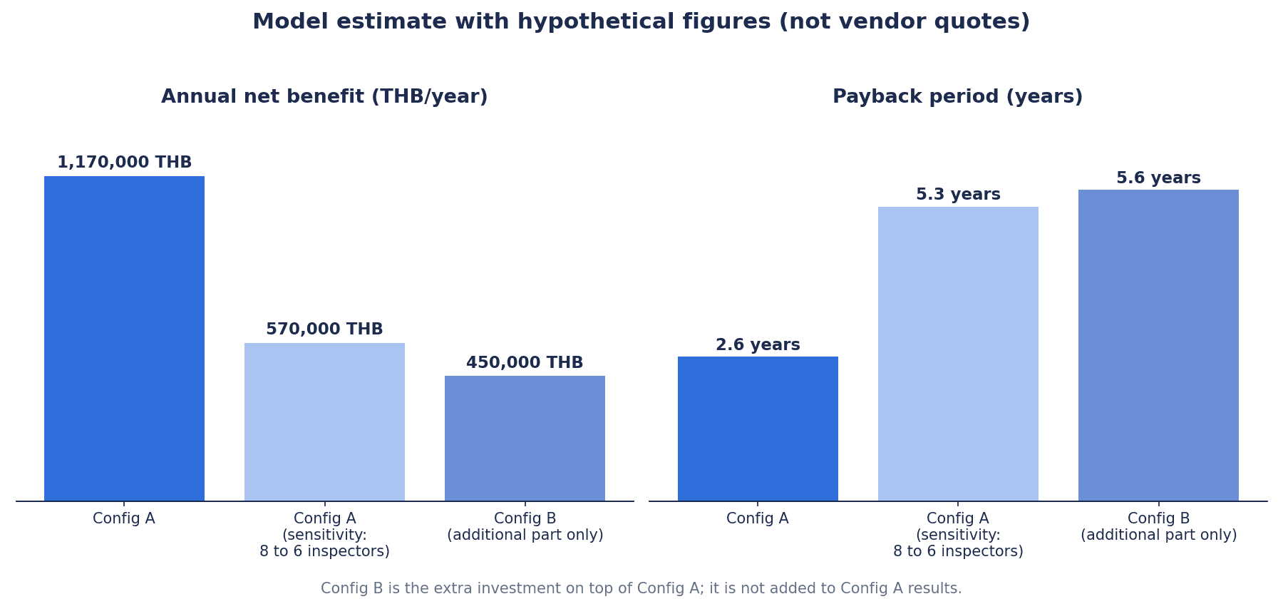
| Annual net benefit | 1,470,000 − 300,000 | 1,170,000 |
| Payback period | 3,000,000 ÷ 1,170,000 | About 2.6 years |
Sensitivity: Configuration A when inspectors are reduced only from 8 to 6
| Item | Calculation | Amount (THB) |
|---|---|---|
| Total annual benefit | 2 people × 300,000 = 600,000, + 270,000 | 870,000 |
| Annual net benefit | 870,000 − 300,000 | 570,000 |
| Payback period | 3,000,000 ÷ 570,000 | About 5.3 years |
Configuration B: the additional portion when multi-direction lighting and 3-surface robotic imaging are added after Configuration A is installed
| Item | Calculation | Amount (THB) |
|---|---|---|
| Additional initial cost | Placeholder | 2,500,000 |
| Additional annual operating cost | Placeholder | 150,000 |
| Additional benefit | Inspectors remaining after Configuration A, 4 people → 2 people, 2 people × 300,000 | 600,000 |
| Additional net benefit | 600,000 − 150,000 | 450,000 |
| Payback period of the additional portion | 2,500,000 ÷ 450,000 | About 5.6 years |
How to read the calculation
- The payback period of Configuration A varies greatly depending on how much inspector workload can be replaced. With 8 people → 4 people it is about 2.6 years, but if it stays at 8 people → 6 people it extends to about 5.3 years. If the gray rate is high and much human re-judgment remains, the result moves closer to the latter
- Configuration B is the difference in the world after Configuration A has been installed. It counts only the benefit of reducing the 4 people remaining after Configuration A to 2, and does not double count the benefit of Configuration A. The more surfaces are inspected, the more the cost of fixtures and robots weighs. The payback of the additional portion is about 5.6 years, longer than Configuration A alone
- The “30% reduction in escaped defect handling” assumes that misses are checked through parallel running and that the procedure for sending gray judgments back to people is working. Do not count this benefit until the number of misses can be confirmed through parallel running
- The reduction in inspectors is considered as replacement of workload, including redeployment. The calculation does not assume dismissals. The freed-up workload can also be used for re-judging gray cases, maintaining boundary samples and countermeasures against defect causes
Frequently Asked Questions
What is AI visual inspection for metal parts, and how does it differ from rule-based machine vision?
Rule-based machine vision judges defects using rules set by people, such as brightness thresholds and areas. On metal surfaces, halation from gloss and the influence of cast skin and machining marks make the rules complicated, and over-detection tends to increase. AI-based visual inspection learns judgment criteria from images of good parts and defects. While it makes it easier to learn surface variation, what it was taught determines the results. Rather than choosing one or the other, there is also the approach of using each for different items.
Can AI be used even with few defect samples?
With anomaly detection trained only on good-part images, training can start without any defect samples. However, evaluation requires defect samples. This is because the only way to count misses is to run actual defective parts and check. If you first set up a mechanism to save the image and the physical part each time a defect occurs, later evaluation becomes easier.
Can scratches on mirror-finished or plated parts also be detected?
It depends on the imaging method. On near-mirror surfaces, methods that assume diffuse reflection cannot be used as they are. Other methods, such as imaging that uses specular reflection or deflectometry, which looks at distortions in reflections, become candidates. On plated parts, distinguishing color tone variations from scratches can be difficult. First, run an imaging test with your own parts and check whether defects appear clearly in the images.
Can scratch inspection automation bring the number of inspectors to zero?
It is realistic to assume that inspectors’ roles will remain. Re-judging gray cases, monitoring misses, updating boundary samples and checking images on which AI and people disagree all require human judgment. The benefit of automation comes from replacing the workload of visually inspecting every part with these judgment tasks.
How much does AI visual inspection cost?
Few products have public prices, and most are quoted individually. Asking for quotations split into hardware (cameras, lighting, fixtures, PCs), software licenses, training and tuning work, and maintenance makes comparison easier. The calculation in this article uses hypothetical numbers for this article. Start by measuring your own inspector workload and escaped-defect handling costs as the baseline.
How many images are needed for training?
It varies by product, defect type and AI approach. Vendor documents sometimes give guidelines. For example, LandingLens’s documentation recommends 50 or more Normal images for anomaly detection. Keyence explains that its VS series can be trained with a general-purpose PC and dozens of images. However, these are descriptions of each company’s products, not numbers that apply to every part. Collecting images that include differences in lots and dies can matter more than the number of images.
How long does implementation take?
It depends on the number of target parts and defect types, and on how well boundary samples are prepared. If boundary samples are in place and there is one target surface, it is shorter; if there are many parts or surfaces and the criteria need to be rebuilt, it is longer. A realistic approach is to expand the scope while confirming acceptance for each defect type at each stage of PoC, FAT and SAT.
Summary
- Whether metal surface defect inspection AI succeeds is largely decided by the imaging method (how to light the part) and boundary samples (judgment criteria), before the choice of AI model
- On metal, halation from gloss, cast skin and machining marks make rules complicated. On near-mirror surfaces, methods that assume diffuse reflection cannot be used as they are
- Choose the imaging method from diffuse, coaxial, multi-direction, specular and deflectometry by testing actual parts, matching it to surface properties and defects
- At sites with few defect samples, start with good-part anomaly detection, and add supervised learning when you want to separate defect types. Combining them or using them alongside rule-based tools are also options
- Figures from research datasets are not factory detection rates. Decide acceptance criteria by counting misses and over-detections separately for each defect type, and set the tolerance for misses strictly
- Send gray judgments back to people, and pass judgment results, linked with image, lot and equipment conditions, on to quality data and traceability
- In the RFP, ask for quotations split into hardware, licenses, training and tuning, and maintenance; reproduce boundary samples and actual defects in FAT; and run in parallel with visual inspection and cross-check in SAT
Whether you are deciding which surface of which part to start with, working out how to reorganize old boundary samples, or would like to try an imaging test with actual parts, TOMAS TECH is happy to help at any of these stages. Please contact us through this form.
References
- Visual inspection of metal parts using deep learning (Hyogo Prefectural Institute of Technology, 2023-07-25) https://www.hyogo-kg.jp/download/publish/report_32/rep32-s31.pdf
- FY2021 subsidy program for introducing AI and IoT to manufacturing sites, results report (Shiga Industrial Support Plaza, 2022-05) https://shigaplaza.or.jp/wp-content/uploads/2022/05/6b1e251a723a44636b8970506ad6214a.pdf
- COSM introduces AI visual inspection solution at Ito Kinzoku Kogyo (ASCII.jp, 2025-02-14) https://ascii.jp/elem/000/004/251/4251509/
- About sensory inspection in manufacturing (SMRJ J-Net21, viewed 2026-10-13) https://j-net21.smrj.go.jp/qa/productivity/Q0618.html
- Brilliant Insights – Deflectometry for the inspection of specular surfaces (Fraunhofer IOSB, undated) https://www.vision.fraunhofer.de/content/dam/vision/en/documents/webshop/brochures-and-prospectuses/inspection-of-surfaces/deflectometry-for-the-inspection-of-specular-surfaces.pdf
- LumiTrax specular reflection lighting (KEYENCE, viewed 2026-10-13) https://keyence.com/ss/products/vision/vj/lumitrax_r.jsp
- LumiTrax lighting (KEYENCE, viewed 2026-10-13) https://keyence.com/ss/products/vision/vj/lumitrax.jsp
- Machine Vision System Selection Guide – high-performance lighting (KEYENCE, viewed 2026-10-13) https://www.keyence.com/ss/products/vision/high-performance-lighting/
- Vision System with Built-in AI VS series (KEYENCE, viewed 2026-10-13) https://www.keyence.com/VS_series
- Anomaly Detection and Global Context Anomaly Detection – HALCON 25.11 (MVTec Software, viewed 2026-10-13) https://www.mvtec.com/doc/halcon/2511/en/toc_deeplearning_anomalydetection.html
- uncalibrated_photometric_stereo – HALCON 24.05 (MVTec Software, viewed 2026-10-13) https://www.mvtec.com/doc/halcon/2405/en/uncalibrated_photometric_stereo.html
- New FH Vision System with industry’s first AI defect detection (OMRON Industrial Automation Europe, 2020-09-01) https://industrial.omron.eu/en/news-events/news/fh-vision-system-with-ai
- Anomaly Detection – LandingLens documentation (LandingAI, viewed 2026-10-13) https://landinglens.docs.landing.ai/anomaly-detection
- Plans – LandingLens documentation (LandingAI, viewed 2026-10-13) https://landinglens.docs.landing.ai/plans.md
- Basler Pylon AI Platform (Graftek Imaging, viewed 2026-10-13) https://graftek.com/?p=20760
- Case study automotive (deevio, undated) https://deevio.ai/case-study-automotive
- MVTec Anomaly Detection Dataset – MVTec AD (MVTec Software, viewed 2026-10-13) https://www.mvtec.com/company/research/datasets/mvtec-ad
- Towards Total Recall in Industrial Anomaly Detection – arXiv 2106.08265 (Roth et al. / arXiv, 2021-06-15) https://arxiv.org/abs/2106.08265
- Towards Total Recall in Industrial Anomaly Detection – ar5iv HTML (Roth et al. / ar5iv, 2021) https://ar5iv.labs.arxiv.org/html/2106.08265
- anomalib mvtecad.py – MVTec AD category definitions (Intel OpenVINO anomalib / GitHub, viewed 2026-10-13) https://raw.githubusercontent.com/openvinotoolkit/anomalib/main/src/anomalib/data/datasets/image/mvtecad.py
- Thailand’s August car production rises 10.9% on year (Capital.com / Reuters, 2026-09-28) https://capital.com/en-gb/news/thailand-s-august-car-production-rises-10-9-on-year
- Thai August factory output rises 4.44% y/y, beats forecast (The Star / Reuters, 2026-09-30) https://www.thestar.com.my/business/business-news/2026/09/30/thai-august-factory-output-rises-444-yy-beats-forecast
- Thailand Manufacturing PMI (Trading Economics, 2026-10) https://tradingeconomics.com/thailand/manufacturing-pmi
- Thailand Business Confidence Remains Subdued (Trading Economics, 2026-10) https://tradingeconomics.com/thailand/business-confidence/news/589079
- PR No.117/2569 Thailand Secures $43.6bn 1H 2026 Investment Surge (Thailand BOI, 2026-07-23) https://www.boi.go.th/upload/content/PR117_2569EN.pdf


