



Implementing AI visual inspection for injection-molded parts begins with a specification, not a model name. Define where and at what severity a short shot, flash, sink mark or burn mark becomes unacceptable. Present each part to the camera in a repeatable pose and under controlled light. Then make sure the decision follows that same part to its good, reject or review destination. This guide helps quality, production and engineering teams in Thailand turn sample collection into an RFP and measurable FAT/SAT tests.
Our injection-molding parameter optimization guide concerns recommendations for machine settings. Here, the object of inspection is the actual ejected part. The article also narrows the broad AI visual inspection introduction to resin color, gloss, parting lines, multiple cavities and temperature immediately after ejection.
Define the molded-part inspection scope
These defects do not have one visual signature. A short shot is an incompletely filled feature, such as a rib, clip or edge. Flash is excess polymer escaping at a mold separation. A sink mark is a local surface depression associated with shrinkage. A burn mark appears as discoloration. Autodesk’s Moldflow documentation explains these as distinct molding phenomena. Process data may be needed to diagnose their causes, but the inspection project first needs an agreed location and disposition for each visible feature.
| Defect | Visual cue | Candidate image setup | What the image alone cannot prove |
|---|---|---|---|
| Short shot | Missing edge, hole, rib or clip | Backlight for silhouette; another view where necessary | Hidden voids or mechanical strength |
| Flash | Protrusion along parting line | Oblique light and edge view | Dimensional compliance without calibrated measurement |
| Sink mark | Local depression or bent reflection | Fixed-angle surface lighting; shape measurement if required | Actual depth from brightness alone |
| Burn mark | Local dark or brown discoloration | Controlled color lighting and camera | Cause or material strength |
The same amount of flash may be critical on a mating surface and acceptable as a trimmed gate trace elsewhere. A visible surface may have a different sink-mark limit from a hidden face. Build an acceptance matrix by SKU, mold, cavity, face, location and intended function. Keep appearance separate from dimensions: ISO 20457:2026 addresses geometrical and dimensional tolerances and acceptance conditions for plastic molded parts but explicitly excludes surface imperfections such as sink marks. Agree visual limits through customer requirements, approved samples and functional needs.
Give every class a disposition, including review
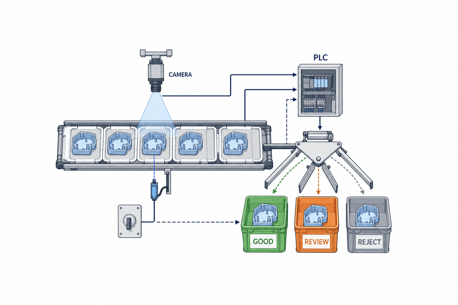
A simple good/bad choice pushes ambiguous samples into an unofficial pile beside the machine. Define three controlled exits: reject, review and good. A functional short shot might be an immediate reject. A borderline visual blemish might go to review. Review material must be physically blocked from the shipping route until an authorized person records a decision.
The defect catalogue needs more than names. For each class, include a drawing of the area, imaging face, smallest relevant feature, allowed good variation, example images and the final decision owner. Separate flash from permitted gate residue. Separate burn discoloration from normal resin pigment variation and part markings. Distinguish a short shot from a deliberately different SKU. When the drawing, mold, resin grade or color changes, update the catalogue and decide who calls for retesting. Our annotation workflow guide discusses label ownership and disagreement review; this project must connect that governance to physical samples and machine acceptance.

Stabilize pose and part identity from press to camera
More training images cannot compensate for a part that arrives at an uncontrolled angle. Compare inspection in the take-out robot’s grip, in a tray fixture, or after singulation on a conveyor. Specify datum faces and pins, allowance for thermal shrinkage and warpage, and contact points that will not scratch the part. Multiple-cavity tools may produce subtle cavity-specific variation. Retain cavity identity if the plant needs to trace a recurring problem to the mold.
A hot part just after ejection can look or measure differently after cooling. Decide whether the early station is intended to detect process problems quickly, whether the final station determines shipment, or whether both are needed. Do not let an early visual pass imply that a later dimensional or functional requirement has passed.
List all faces to inspect by SKU. Inserts, metal terminals, transparent windows, dark resin and deep grooves may require other camera angles or illumination. Test any rotation or flipping device for damage and mix-ups. Compare bids using the smallest relevant defect in the actual field of view and the observed contrast, rather than camera pixel count alone.
Part identity can come from a mark, tray cell, pocket, robot pick order or other verified key. When parts from several cavities converge, the PLC’s concept of the “next part” may drift from the camera result. Tie the image event to SKU, mold, cavity, shot or pocket, result ID and eject event. A printed serial number is not always necessary, but every device must refer to the same physical item.
Test lighting, optics and fixtures against each defect
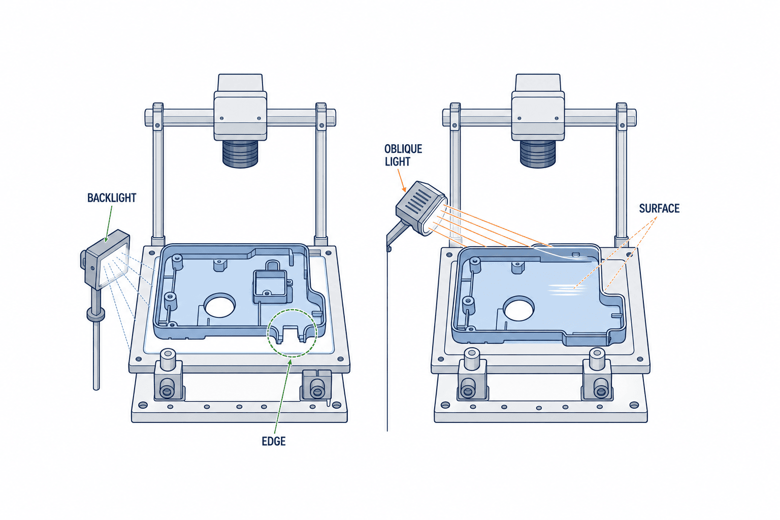
Backlight can make a missing edge easy to see but will not expose a burn mark on the front surface or an obscured hole. Oblique light can emphasize a thin protrusion. To see a shallow sink mark through a reflected pattern, camera and lamp angle must stay fixed; a slight pose shift can look like a defect. Color checks need controlled light spectrum, exposure, white balance and ambient light. Basler’s machine-vision lighting guidance explains why illumination creates the contrast on which an inspection depends.
Run a small imaging comparison before committing to one camera and light. Compare backlight for contours, diffuse light for surfaces, and oblique light for local relief. Record which defects each image makes visible and which remain invisible. More lights add exposure, enclosure, heat, cleaning and service requirements. Collect repeat images across shifts, after cleaning, with lens contamination and with dark, glossy or transparent grades. Our lighting selection guide covers generic lighting choices; the decision here is their fit to each molded-part defect.
Release agent, dust, condensation and static-clung particles may look like a defect. A real flash can hide behind a fixture. Put fixture cleaning, light inspection and camera-position checks into the maintenance plan. When false rejects rise, first re-image the same approved part to see whether capture changed before ordering model retraining.
Keep golden samples and model data under version control
Approve physical golden samples, but do not ask a single pristine part to represent acceptable color, cavity, resin-lot, texture and mold-wear variation. For each SKU, store representative good parts, limit-good parts, clear defects and borderline defects with position and decision rationale. Physical parts age, scratch and discolor; document storage, replacement, original images and drawing revision.
Split training, threshold tuning and untouched acceptance data. If consecutive parts from one shot are scattered across all three sets, the assessment can look stronger than performance on a new day or material lot. Consider splits across date, lot, mold cavity, machine and illumination state. The MVTec AD benchmark illustrates separate defect-free training and defective testing images; its results do not certify a Thai production line. Its dataset also carries a noncommercial license, so do not assume it can be used as commercial training material.
Normal-only anomaly detection can be considered when rejects are scarce. An anomaly score still does not say whether a defect requires shipment to stop. A new marking, accepted pigment range or harmless mold trace can trigger it. Test whether the system locates the suspect area, passes limit-good samples and routes unfamiliar cases to review. Keep a human decision route because every future defect type cannot be trained in advance.
Quality, molding engineering, equipment maintenance and the customer-facing owner must resolve disputed examples together. Do not turn unresolved specifications into arbitrary majority-vote labels. Save final label, reason, date, approver, SKU and drawing revision. Revisit the set when the mold is repaired, a pigment changes or a new customer criterion arrives.
Track the decision all the way to the physical exit
An “NG” result on a screen is not inspection unless the matching part is isolated. Measure travel distance from camera to ejector, conveyor variation, PLC delay, buffer order and pusher or air-jet response. If a robot places good, rejected and review parts in different trays, detect full trays, grip failure, missing trays and misplacement.
For multi-cavity shots, verify image-to-part matching in both FAT and SAT. Randomly mixed samples alone do not challenge shot and cavity order. Alternate good, reject and review parts. Add stop/restart, missing sensor pulses, communications timeout and recipe change; record the final destination of each test part. An item without a valid timely decision should not silently default to the good route. Specify the appropriate fail-safe behavior in the RFP based on product risk and cell architecture.
The review screen should show the original image, candidate defect location, SKU, cavity, reason, threshold and timestamp. An operator override should append a named reason without erasing the original result. Link any repeat image to the same item. Review bins need IDs, shift handover, authorization and disposition for scrap, rework or shipment. “A person will check exceptions” is neither a labor estimate nor a control plan.
Define misses and false rejects by defect
“99% accuracy” cannot be compared without a denominator, severity and SKU mix. For a particular defect, the miss rate is agreed defective samples passed as good divided by all agreed defective samples for that class. The false-reject rate is agreed good samples sent to reject or review divided by all agreed good samples. State whether review counts as successful interception. Report no-image events, inspection failures and ejector failures separately; do not hide them by excluding them from the denominator.
For illustration only, three misses among 100 agreed defective samples produce a 3% miss rate under those test conditions. That is neither a typical device performance claim nor a recommended acceptance limit. Stratify flash by location and sink marks by imaging condition. If a customer requests zero misses for a critical missing clip, determine the sample volume, physical backup checks and second inspection needed. Zero misses in a small sample cannot guarantee zero future misses.
Measure fed parts, valid images, matched recipes, good exits, reject isolation, review cases, eject failures, manual rework and downstream escapes. A yield measured against all fed parts differs from one measured against only imageable parts. Use the same definition for baseline, FAT and SAT. Fast AI decisions provide little labor benefit if the review rate remains high.
Put real molded-part conditions into the RFP
Lead with a one-sentence duty statement: “Inspect three black-resin housing SKUs in our Thai plant after molding for short shots, parting-line flash, visible-face sink marks and burn marks, then route each identified part to good, reject or review.” Replace the example with the actual product. Photos and “inspect everything with AI” allow bidders to price different scopes.
| RFP input | Supply | Design impact |
|---|---|---|
| Product and drawing | SKUs, resin and color, texture, faces, drawing and customer revision | Inspection areas and acceptance limits |
| Molding and flow | Mold and cavity count, shot cycle, take-out and cooling point | Fixture, cameras and part identity |
| Samples | Defects, limit-good, rejects, disputes and frequency | Training, evaluation and review |
| Environment | Ambient light, dust, release agent, vibration, cleaning | Lighting, enclosure and maintenance |
| Interfaces | PLC, robot, MES, recipes and log retention | Eject synchronization and recovery |
| Acceptance | Counts and limits by defect, continuous run and retests | Unambiguous FAT/SAT |
Ask bidders to separate camera, lens, lights, fixture, flipping device, PC and AI license, PLC changes, eject hardware, sample preparation, installation, training, spares, retraining and local Thai support. A remote photo proof of concept differs from SAT on a working line. Quote the cost of new SKUs, colors and mold revisions, license renewals and image storage. Include review labor, escapes and false rejects in the ownership calculation instead of comparing initial prices alone.
If some visual limits are still unresolved, list them as PoC deliverables with a due date and approver. State sample ownership, image-use rights, remote-access limits and what model, recipe and dataset artifacts the supplier will hand over. An unstated inspection boundary becomes a FAT dispute.
Gate the PoC from imaging to sorting
Gate one is repeatable capture: can the hardest dark, glossy, clear or textured combination reveal the agreed defect? Gate two is classification on independent good, bad and boundary samples with separate miss and false-reject counts. Gate three is physical routing under actual speed changes and stop/restart. Record the exact tested envelope, including exclusions.
If a gate fails, consider another view, fixture, lighting scheme, cooling point, calibrated dimensional check or molding-process fix before merely increasing model complexity. A model cannot restore a hidden surface. Preserve failed images as well as successful ones, with light settings, focus, fixture and model version, lot, cavity, time and exit. Mark a class “not evaluated” if its sample set is inadequate. Quality must choose additional samples, parallel checks or process controls for critical defects.
Carry the same acceptance table through FAT and SAT
Do not stop at an average across mold cavities
In a multi-cavity mold, cavity position and cooling conditions can make color, gloss and flash differ even within one shot. For acceptance, inspect valid-image counts, false rejects of good parts and misses of defective parts by cavity, not only the average across good parts from all cavities. If parts from just one cavity tilt against the fixture, the overall mean may look favorable while shipments from that cavity suffer. Molding and equipment teams should confirm the order in which each cavity enters the camera field of view and whether that order stays the same after a mold change.
Naturally occurring defects may not be available equally from all cavities. Disclose the actual sample composition and mark missing cavity–defect combinations as “not tested.” Do not copy defect images from one cavity into another cavity’s group to inflate evaluation counts. During the test, do more than run a long block of the same defect: place a defective part between good and borderline parts and check that the previous part’s decision is not applied to the next part’s ejector. Even when image classification is correct, a one-part tracking shift can cause both a defective escape and the disposal of a good part.
Decide acceptance authority before the test
If the team first debates whether a sink mark is acceptable on the day of acceptance, it cannot distinguish supplier performance from an unresolved customer specification. Before testing, quality approves limit samples, production confirms normal material, mold and cycle conditions, and equipment engineering approves handling and eject conditions. The supplier confirms that it can test with those same samples and conditions. If a customer decision is needed for a cosmetic case, keep those parts out of the acceptance denominator while awaiting the answer, and define a temporary review route.
After a disagreement, determine whether the model missed the defect, the image was unclear, the visual limit had not been approved, or the physical destination was wrong. On retest, record whether the same stored images were rescored or new images were captured after changing light or fixture; retain the first results. Reporting only the best score after repeated setting changes hides the performance that can be sustained in production. Bring the change history into SAT and turn it into an adjustment procedure that plant staff can reproduce.
At quotation and acceptance, list sample quantity separately from sample diversity. One thousand good parts of one color and cavity do not establish performance for another color or night-shift lighting. Many images of a single defective part from different angles still represent one independent defective specimen. Record collection date, shot, resin lot, cavity and storage condition so evaluators can trace every sample. If genuine defects are rare, state the gap as a contractual limit and set a deadline for additional sampling and reassessment early in production. The plant and supplier can then manage remaining uncertainty in the same table without overstating a laboratory result.
FAT uses agreed samples at the supplier’s facility to check detection, sorting, logs and fault handling. SAT tests the Thai line with its ambient light, vibration, resin lots, shifts, PLC signals and maintenance practices. Passing FAT does not establish SAT performance. NIST’s AI RMF Core recommends representative evaluation, production monitoring and safe behavior outside the developed operating conditions. It supplies a risk-management approach, not a prescribed performance percentage for molded-part inspection.
| Test | FAT | SAT addition | Evidence |
|---|---|---|---|
| Defect decisions | Independent samples by SKU, face and class | Real lots, cavities and shifts | Image, label, result, model version |
| Capture | Light, focus, pose and simulated dirt | Actual daylight, cleaning and vibration | Settings and repeat images |
| Sorting | Alternate good, bad and review | Plant PLC, stop/restart and full bins | Part ID, time and final tray |
| Faults | Camera, network and timeout | Power recovery and recalibration | Alarm and signed recovery record |
| Operation | Recipe change and image storage | Local operator performs procedures | Training and manual revision |
Write sample counts, selector, severity, denominators, thresholds, exclusions, allowed retests and signers into the contract. Carrying a FAT issue into SAT requires a named interim control, owner, deadline and release condition. At SAT, plant staff should start, change SKU, clean, recover from faults and handle review material during ordinary shifts. Test screens and instructions in the languages staff actually use.
Manage change and support after acceptance
Molds wear; resin, pigment, light, lens and fixture change. Monitor false rejects, review proportion, failed images, unfamiliar patterns, customer defects and recipe changes. Investigate optics, fixture, material, mold and PLC events before deciding on retraining. Compare old and new models on the same untouched acceptance set and retain a rollback path. Track results at least by SKU, defect and capture condition so common good parts cannot mask a rare serious short shot.
Connect the model version to the defect-catalogue revision and the first lot inspected with it. Define image retention, access, backup and a field of view that avoids unnecessary personal data. If inference depends on a cloud service, specify outage behavior and latency limits. A support agreement should assign camera, light, fixture, software, PLC and ejector responsibilities, with synchronized timestamps and decision IDs. Include calibration parts, spares, response times in Thailand, extra SKU pricing and the recorded manual-inspection fallback.
Frequently asked questions
Can one camera detect both short shots and flash?
Sometimes, but silhouette imaging for missing geometry and oblique lighting for thin flash have different needs. Test the smallest defect, face and pose on real parts. A hidden backside cannot be guaranteed from one front view.
Can an ordinary 2D camera measure sink depth?
It may flag a suspicious reflection, but brightness alone cannot establish physical depth. If depth is a contractual acceptance value, evaluate calibrated shape measurement. Keep surface-appearance and dimensional requirements distinct.
Can the project start with very few defective samples?
Normal-only anomaly methods and purpose-made test pieces can establish imaging feasibility. They cannot guarantee detection of every future defect. Record the missing acceptance evidence and provide review and additional-test paths.
Can AI replace final shipment inspection?
Decide after checking customer requirements, hidden defects, product risk and physical sorting. Visual AI does not establish internal integrity or strength. Keep dimensional and functional tests where they are required.
What must be held constant when comparing quotations?
Use the same SKUs, faces, minimum defects, takt, three-way routing, logs and FAT/SAT samples and limits. Separate fixture, lighting, PLC changes, new SKUs and support costs.
Conclusion
AI inspection of injection-molded parts is an end-to-end agreement on location, limit, image, decision and destination for each defect and physical part. Start with drawings and approved samples, stabilize pose and illumination, quantify misses and false rejects by defect on independent samples, and test real sorting in FAT and SAT.
If your Thai plant is still defining samples or its current molding flow, contact TOMAS TECH. We can help structure the defect catalogue and capture/routing requirements into a usable RFP before equipment selection.


