



Are you ordering a replacement cam follower by matching only its outside and stud diameters? On an automatic machine, a roller contacting a cam plate or guide rail can become unusable because of track wear, edge loading, inadequate lubrication or stud bending before internal rolling fatigue becomes the limiting factor. This guide takes Thailand factory projects from defining loads through comparing stud and yoke styles, preparing an RFQ, and checking the assembly at FAT and SAT.
Select the bearing and its mating track together
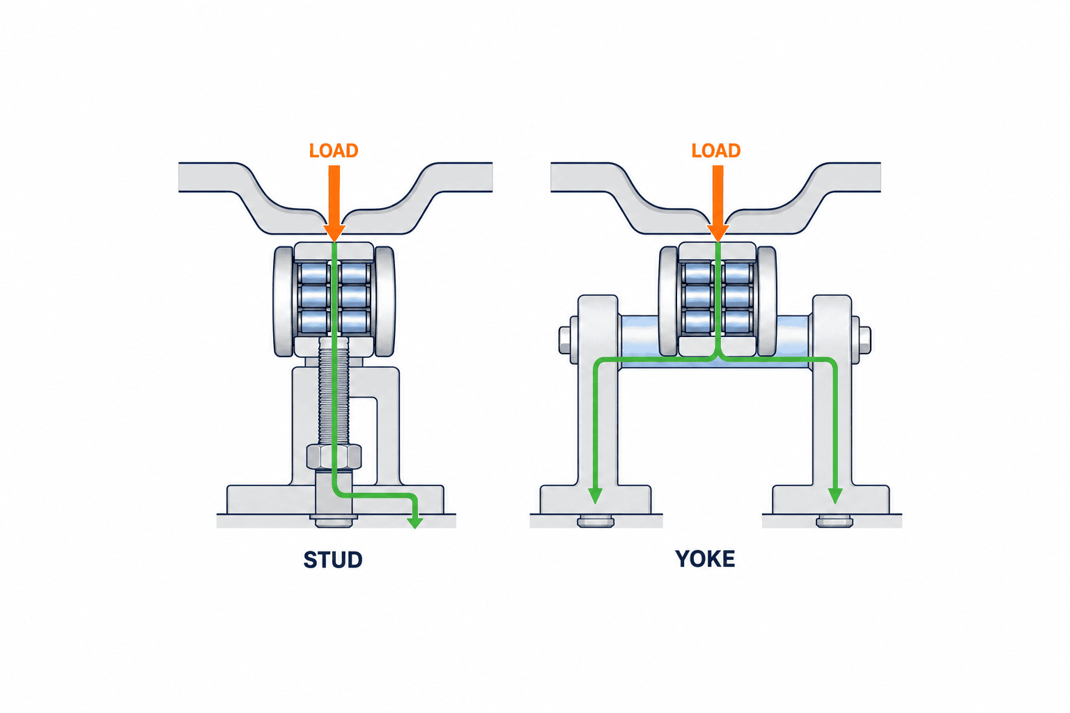
A cam follower is a bearing with a thick outer ring that rolls on a cam, rail or stop surface. A stud type integrates a threaded shaft and can be mounted comparatively simply to a bracket. A yoke type track roller uses a separate shaft or inner ring and can be arranged with supports on both sides. Similar looking rolling elements do not make their mounting stiffness or load paths identical. Schaeffler describes both as thick outer-ring rollers that run on a mating track, while a stud type replaces the inner ring with an integrated heavy stud.
Before comparing part numbers, draw the point of contact and the path by which force reaches the bracket. Vertical payload alone omits spring preload, cam acceleration, impact, eccentric workpieces and steps at rail joints. Even with equal bearing ratings, a long cantilevered stud and a short shaft supported on both sides deform differently. The assembly, including the cam profile or rail material, is the unit of selection.
Freeze the operating inputs first
Record roller diameter and width, quantity, direction of rotation, speed, contact duration within a cycle and target operating hours. Separate normal running, start/stop, emergency stopping, jam recovery and manual setup as load cases. Do not mix radial loads and lateral axial forces. Record eccentric adjustment, bracket thickness, hole diameter and squareness, support-face diameter, space for the nut wrench and grease access. For the track, document material, hardness, surface finish, width, joints and exposure to oil or chips. When an input is unknown, separate normal and maximum assumptions and mark it as unconfirmed in the RFQ.
Boundary with linear guides and ball screws
A cam follower tracks a cam profile or rolls against a local guide surface. It does not by itself guarantee the attitude and positioning accuracy of an entire linear axis. For carriage loads, moments and datum surfaces, also review the linear guide selection guide. Feed force, speed and accuracy on the drive side belong to ball screw selection. Rate the roller, guide and drive separately, then verify the assembled axis in operation.
Check four criteria for cam follower load and life
“Load capacity” on a component table is not a single number. THK’s cam follower selection material treats rolling fatigue life from the basic dynamic load rating C, the safety factor against basic static load rating C0, and the safety factor against permissible stud load F0 separately. There is also track load capacity for repeated contact between the outer ring and mating material. A sufficient C does not rule out a bent stud or worn rail.
Keep maximum load separate from life calculation load
Check the worst credible radial load P0 against both C0 and F0. THK gives lower-limit static safety-factor estimates of 1–2 for normal loads and 2–3 for impact loads. These are manufacturer guidelines conditional on adequate lubrication and sound installation, not universal guarantees. A long period at moderate load and a brief large impact need separate checks. If you can measure a load waveform, align roller position, speed and load by cycle segment. Otherwise state the range derived from spring force, mass, acceleration and cam slope, and revise it during commissioning.
For a needle-roller cam follower under THK’s catalogue conditions, basic rating life is L10 = 10^6 × (C/Pc)^(10/3) revolutions. Pc is the radial load used for life evaluation, and C is the candidate model’s basic dynamic load rating. Do not interpret this constant-load equation as an automatic replacement date. For varying cyclic loads, obtain an equivalent load by the manufacturer’s method and assess temperature, lubrication, contamination and misalignment separately. L10 is a statistical rolling-fatigue measure for a group of identical bearings. It does not promise that a particular unit will survive until that count.
Track load capacity and mating-material hardness
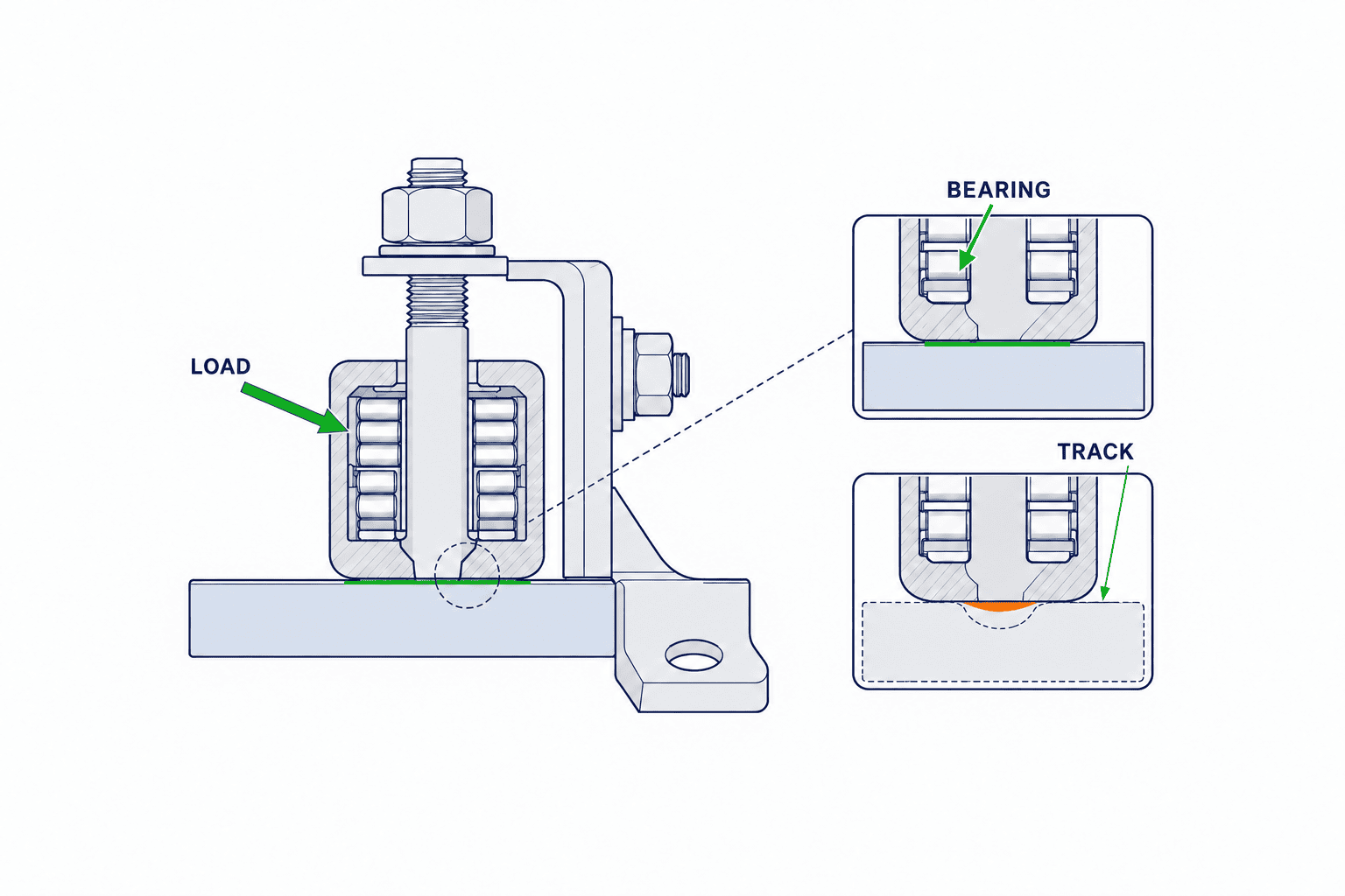
If the cam plate or rail is soft, it can indent or wear before the bearing reaches its own limit. THK defines track load capacity as permissible repeated-use load for the outer ring and mating track. Its tabulated value assumes a specified mating-material strength and is adjusted with a factor for the actual material hardness. Thus “the bearing has C of x kN” cannot prove that the rail handles x kN. State contact-surface hardness after heat treatment, case depth, flatness, finish and a replaceable track arrangement on the drawing. A trial on an unhardened prototype rail is not production acceptance evidence for a heat-treated rail.
A worked comparison without invented catalogue data
Suppose the team’s design inputs are a 1.2 kN maximum and a 0.6 kN normal equivalent radial load. Obtain C, C0, F0 and track capacity for each candidate model from the current table under the actual contact conditions. Ask each bidder to return in one table: maximum 1.2 kN against C0 and F0; life using 0.6 kN against C; and track capacity corrected for the specified rail material and hardness. The two example loads are explanatory assumptions, not TOMAS TECH measurements or general design values. Keep the model number, catalogue edition, units, load case, formula, factors, margin and approver with the calculation. A bare “20,000-hour life” cannot be compared.
Compare stud and yoke types by mounting architecture
Stud types can reduce mounting parts and suit compact cam mechanisms, but their cantilevered stud and fastening condition matter. A yoke type allows a separately engineered shaft and two-sided support where radial capacity or stiffness requires it, but adds shaft, spacer, plate, tolerance and assembly costs. Avoid the simplistic rule “stud for light load, yoke for heavy load.” Compare permissible loads, mount stiffness, service access, machining and total installed cost. Schaeffler also documents yoke options with or without inner rings, axial guidance, seals and different outer-ring profiles.
Cylindrical versus crowned outer ring
A cylindrical outer ring can offer broad contact on a flat, well-aligned track, but tilt concentrates load near an edge. A crowned outer ring can reduce edge loading from small angular errors, while its actual contact width and pressure still require checking. THK recommends a spherically ground model where the outer ring contacts the track unevenly. Crowning does not absorb every mounting error. During machine testing, inspect the contact pattern, edge wear and roller tilt. Moving towards a narrower contact patch also raises the importance of track material hardness.
Eccentric studs and adjustment
An eccentric style permits fine radial adjustment of outer-ring position to set clearance or contact force against a rail. If tightening rotates the eccentric, the intended setting will not repeat. Show datum, adjustment direction and range, tightening order, final clearance and locking method in both drawing and work instruction. Schaeffler explains that an eccentric collar matches the outer-ring position to the mating track. Do not use adjustment range to hide a badly machined bracket: replacement then becomes difficult. With multiple rollers enclosing one rail, watch motor current and temperature under actual loading to avoid excessive internal load and frictional heat from over-preload.
Seals and cages
Where chips, dust, washing liquid or mist are present, consider both bearing seals and external guards. A sealed bearing still leaves the outer-ring-to-track surface exposed; it needs its own lubrication and cleaning plan. Caged and full-complement constructions differ in internal geometry, rating, allowable speed and relubrication needs, even at the same envelope size. IKO’s catalogue distinguishes standard, eccentric, full-complement and sealed variants. THK’s maintenance guidance gives different indicative grease intervals for caged and full-complement versions. If the specification says “equivalent accepted,” include internal design and grease method in the equivalence test, not only outside diameter.
How mounting errors shorten service life
THK recommends squareness between stud hole and mounting surface, a small chamfer at the hole entry and a support-face diameter at least as large as the specified dimension. A tilted hole makes the outer ring run obliquely and concentrates the nominal radial load locally. Fastening only into a thin threaded plate or overhanging the roller far from the bracket increases stud bending. Check bracket stiffness and post-weld distortion; measure hole location and squareness after machining. For production equipment, retain an exchange-setting jig so that technicians do not have to restore eccentric position by feel.
Use the tightening torque for the exact model and control thread condition and tool calibration. Do not grip the outer ring to torque the stud, hammer the stud head or over-tighten to compensate for bending. THK describes proper nut retention for standard types and cautions against applying an easy-mount design unconditionally to vibration and impact. IKO cautions against directly striking the stud head and locating a stud oil hole in a high-load zone. After assembly, check smooth movement under representative load, not only a free spin with no load.
Design lubrication for both internal and external contacts
The rolling elements inside a cam follower and the contact between its outer ring and cam or rail have different lubrication paths. Alongside its description of initial grease, THK instructs users to lubricate the rolling contact surface before use. “Sealed” does not mean “no external care.” If food or electronics is nearby, agree with quality staff on permissible grease escape and design a cover, collection point and wiping procedure. For water, detergent or coolant exposure, check grease compatibility, seal material, corrosion protection and the relubrication path for the actual part number.
Some small models have no grease port and cannot be replenished. For its own products, THK gives indicative intervals of six months to two years for caged styles and one to six months for full-complement styles, explicitly dependent on conditions. Do not carry those intervals across brands as a universal maintenance rule. Schaeffler’s mounting handbook emphasizes initial and replenishment grease compatibility, filled supply passages and a path for spent grease to leave. Maintenance instructions should state part number, grease, port, quantity, interval-setting method and inspection of removed parts. Adjust the interval using temperature and wear observed after startup.
What to put in an RFQ for a Thailand factory
Use a common functional brief and acceptance evidence before requesting multiple quotes. Attach machine and process descriptions, workpiece data, cam and rail drawings, load and speed by cycle, annual duty, temperature, humidity, dust and washing conditions. For a replacement project, supply the failed part’s wear photographs, failure position, hours, lubrication history, rail hardness and measured mount dimensions, not merely its part number. A larger bearing will not solve a soft track or flexible bracket. For Thailand procurement, check full suffix, seal and grease specification, local stock, replacement tools, lead time and approval of alternatives. Repeat availability after a breakdown can matter more than a small initial unit-price saving.
The bid sheet should show structure, C/C0/F0, track capacity for the specified material, static safety under maximum load, life assumptions, outer-ring profile, lubrication, mounting dimensions, permitted torque, catalogue revision and drawings. Different manufacturers may define symbols and ratings differently; do not rank bids simply by the largest number. Require an installed trial that includes track and bracket for an “equivalent” substitute. Even before the final model is chosen, listing who will settle each unknown input and when makes the later cost boundary visible.
FAT checks
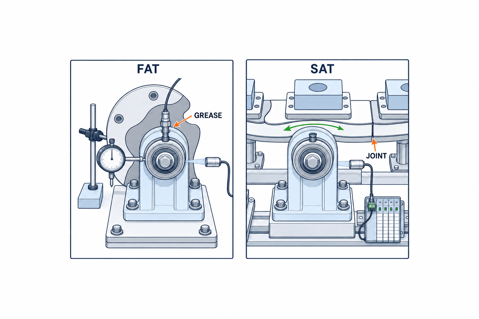
At factory acceptance, first match model and production lot, drawing dimensions, bracket squareness, torque record, oil-hole orientation and grease routes. In no-load, normal-load and safe worst-case simulations, record binding, contact pattern, motor current, vibration/noise and temperature. Agree numerical limits from the machine requirement and initial measurement, not one universal catalogue threshold. Fix inaccessible grease points and non-removable guards now. A short FAT run does not demonstrate rated life; it gathers evidence for the load analysis and assembly quality.
SAT checks
At site acceptance, run with actual power, ambient temperature, humidity, workpiece variation, production speed and cleaning method. Rail joints, machine leveling and frame anchoring can alter contact from FAT conditions. During initial operation, repeat contact-pattern and temperature measurements at the same positions and check grease escape and contamination after replenishment. Observe whether a stop/recovery event derails a roller or produces unexpected impact. Preserve measurement location, duty, photos, instruments and responsible person as a baseline for replacement.
Diagnose existing failures before specifying a retrofit
If an installed cam follower fails quickly, map the failure location before ordering the same part again. One-sided outer-ring polish calls for measuring hole squareness, bracket bending, cam-plate warping and axial roller position. Periodic dents on the track suggest checking jam stop positions, workpiece impact and rail joints. Discoloration or seizure inside the bearing calls for checking blocked grease passages, mixed lubricant, seal damage and excessive preload, as well as grease quantity. A new outer ring can temporarily erase a contact mark while the root cause stays in place.
At minimum, photograph the assembly before removal, mark the contact position, photograph both sides of the removed part, measure bracket and track, and record recent operation and the machine state at failure. If one of several symmetric rollers fails, compare load sharing and plate twist before assigning blame to a manufacturing variation. If all wear on the same schedule, look first at shared lubrication, track material and duty. Record each hypothesis and its check so that a supplier’s new model can be judged by the failure mode it actually addresses.
Upsizing only the roller in a retrofit may change effective cam profile, stroke end, clearance to adjacent parts and contact force. A new outside diameter is a machine-timing change. A larger stud changes bracket holes, seats and tools. The same nominal size from another maker may have a different outer-ring width, overall length, shoulder or projecting seal. Confirm dimensional interchangeability against drawings; confirm functional interchangeability with load, speed, lubrication and an installed trial.
Engineer maintenance while the machine is designed
For imported bearings in Thailand, the serviceable layout matters as much as procurement lead time. Check that a grease gun reaches the fitting straight, guard removal brings the machine to a safe state, and roller replacement does not require removing the whole cam plate. A stud end with no tool clearance prevents routine torque checks. A service window that admits chips also needs a guard redesign. Include tools, replacement parts, grease, drawing revision and torque record sheet in the equipment handover.
The spare list should give the complete model code and explain suffixes governing outer-ring profile, seal, material, grease port or eccentric arrangement. Follow maker storage and rust-prevention conditions for long-held stock. Recording manufacturing lot and replacement date helps distinguish one bad lot from one bad installation position. If alternate makers are approved in advance, reuse the original comparison table and define which track and FAT/SAT checks need repeating.
Do not lock maintenance intervals to a generic catalogue number. Inspect more frequently immediately after startup. Record temperature, sound, contact band, grease escape and track marks after the first run and compare at the next scheduled stop under the same operating conditions. Rising temperature may suggest lubrication or preload; an edgeward contact band may suggest alignment. Neither single symptom proves the cause, so check instruments and ambient conditions. Replace “change when noisy” with photo examples and measurable acceptance bands. This connects the machine builder’s calculation to the factory’s day-to-day decisions.
Compare failure modes before unit prices
After collecting three bids, first exclude models that do not meet mandatory conditions. Correct outer-ring profile for the track, mounting clearance, C0 and F0 under maximum load, track capacity, seals and grease access cannot be compensated by an overall score. Then compare machining, spare availability, downtime for relubrication, ease of replacement and traceability of technical data. A slightly cheaper part can cost more if it requires track heat treatment or bracket rework. Link each score to a drawing, catalogue page or test record so purchasing and engineering approve the same conditions.
Speed is more than “can the roller turn.” Roller speed varies along the cam profile and can accelerate and decelerate over short intervals. When outer-ring sliding grows, life calculations based on ideal rolling become less dependable. Match the model’s permissible speed, internal design, grease and continuous temperature to the servo-axis profile. Where synchronization is uncertain, inspect startup and stopping contact through video and motor-current traces. The shaft coupling selection guide helps with the drive path, although a rated coupling alone does not prove sound roller contact.
Review foreseeable non-normal cases too: a jammed workpiece, the largest conveyed item, cleaning that washes lubricant away and operation immediately after a spare is fitted. Use safe simulated loads and control tests consistent with the machine risk assessment instead of deliberately creating a dangerous jam. Assess stopped position and contact force; add a separate stop or overload detection if necessary. Do not treat a cam follower rating as a safety function.
Leave an unverified item marked unverified. Without measured track hardness, corrected track load capacity is unresolved. Without a drawing of a substitute’s grease route, maintainability is unresolved. Assign who will measure, test or revise the drawing and at which purchasing gate the decision waits. The hold list makes RFQ risk visible. Contract for repeating site-dependent checks at SAT even after FAT passes if the installed rail or bracket differs.
Connect drawings to acceptance records
For each acceptance item, pair what is measured with conditions, pass criterion and evidence location. For example, specify a tool and drawing tolerance for hole squareness; use the assembly arrow and a final photo for grease-hole direction; log torque-tool ID, calibration date, setting and operator. Record heat-treatment lot and hardness measurement location. Photograph the roller contact band after representative cycles under consistent light. Measure temperature and motor current both early and after representative operation, with ambient temperature. If no acceptance limit exists, agree it from design analysis and prototype evidence before FAT, not after a convenient reading appears.
One measurement rarely covers every failure mode. Low temperature does not rule out edge wear, and normal motor current does not prove grease reached the rolling elements. Put calculation, dimensions, surface condition, operational behaviour and maintenance operation into the acceptance sheet. At SAT, compare test workpieces with production workpieces in mass, shape and feed condition. If they differ, revise load cases and repeat C0, F0, life and track-capacity judgments. A single “pass” word loses the assumptions that later retrofit teams need.
If several machines should share a spare part, do not approve all of them solely against the machine with the greatest load. A lower-load machine may run faster, face more washing or lack grease access. List applicable machine IDs, lubricant, stock location and replacement method for each candidate. Check the physical suffix label so that similar but non-interchangeable variants do not enter the common stock.
Seven questions for the final sourcing meeting
Ask every bidder to answer in writing: (1) Which normal or abnormal case produced the maximum load, and in which direction? (2) What are the safety factors against C0 and permissible stud load F0, and how do they compare with the maker’s assumptions? (3) Which cycle segments enter the life equivalent load, and which are excluded? (4) How was track capacity corrected for the real cam or rail material and hardness? (5) How do outer-ring profile and mounting prevent edge load, and what will be measured after machining? (6) How will both internal bearing and external track contact be lubricated, with safe service access? (7) Which FAT and SAT records close acceptance? Only then are unit prices and delivery times comparable.
“No problem” or “standard specification” is not an auditable answer. For life, request C and Pc, units, model, equation, revolutions and conversion to running hours. For lubrication, request port, replenishment possibility, track supply and leakage control, not only a grease trade name. Separate factory-reproducible FAT conditions from site-specific SAT conditions. Attaching those written replies to the purchase specification lets a later engineer reconstruct the decision.
Cam follower selection FAQ
Can L10 hours define a replacement date?
No. L10 is a rolling-fatigue metric under stated conditions. Track wear, poor lubrication, chips, corrosion and loose fastening are separate failure paths. Define inspection and replacement criteria using contact marks, rolling resistance, temperature, sound, grease condition and track dimensions.
How should I choose between stud and yoke types?
Compare cantilevered versus two-sided stiffness, bracket thickness, shaft machining, disassembly and grease access alongside load. A stud type still needs model-specific C0 and F0 checks; a yoke type still needs a designed shaft and mating track.
Does a sealed bearing remove the need to lubricate the cam surface?
No. The seal mainly protects the bearing interior. The outer-ring-to-track contact has separate lubrication needs. Where lubricant can reach product, design contamination control at the same time.
Does a crowned outer ring make alignment irrelevant?
No. It can relieve mild edge loading but cannot compensate for severe tilt or a soft track. Verify real contact marks and temperature, and measure bracket squareness.
What is the minimum information for an RFQ?
Share load cases, speed and duty, cam/rail/bracket drawings, mating-material hardness, environment, target life, maintenance conditions and FAT/SAT acceptance items. Mark unknowns and assign who will measure and settle them.
Conclusion
A cam follower cannot be chosen from outside diameter or C alone. Check maximum load against C0 and permissible stud load F0, life calculation load against C, and outer-ring contact against track capacity. Compare stud or yoke construction, outer-ring shape, mounting squareness, lubrication and track material as one assembly. Carry the RFQ assumptions into FAT and SAT evidence.
Even if loads or rail material are not yet final for a new or retrofitted automatic machine in Thailand, you can contact TOMAS TECH to organize drawings and site conditions during specification work.


