


Selecting a soft starter for a three-phase motor in a Thai factory takes more than matching the motor’s kW to a catalogue row. Start with the motor nameplate full-load current (FLA), load torque during acceleration, the worst starting duty, ambient conditions and the complete feeder. This guide turns those inputs into a request for quotation and a testable FAT/SAT plan. Always confirm the final model and settings against its current manufacturer manual.
1. Decide whether a soft starter is the right device
A soft starter controls the transition between stopped and normal speed, primarily by controlling applied voltage during starting. Depending on the model, it can also shape stopping. It does not provide continuous reduced-speed operation. Schneider Electric’s soft starter versus VFD explanation makes this functional boundary clear. If the process must continuously vary flow, pressure or conveyor speed, compare a variable-frequency drive (VFD). If the motor normally runs at constant line frequency and the concern is shock at startup or shutdown, a soft starter may fit. High-inertia loads and heavy starts still require a torque and thermal check; a slow ramp alone does not guarantee that the load will accelerate.
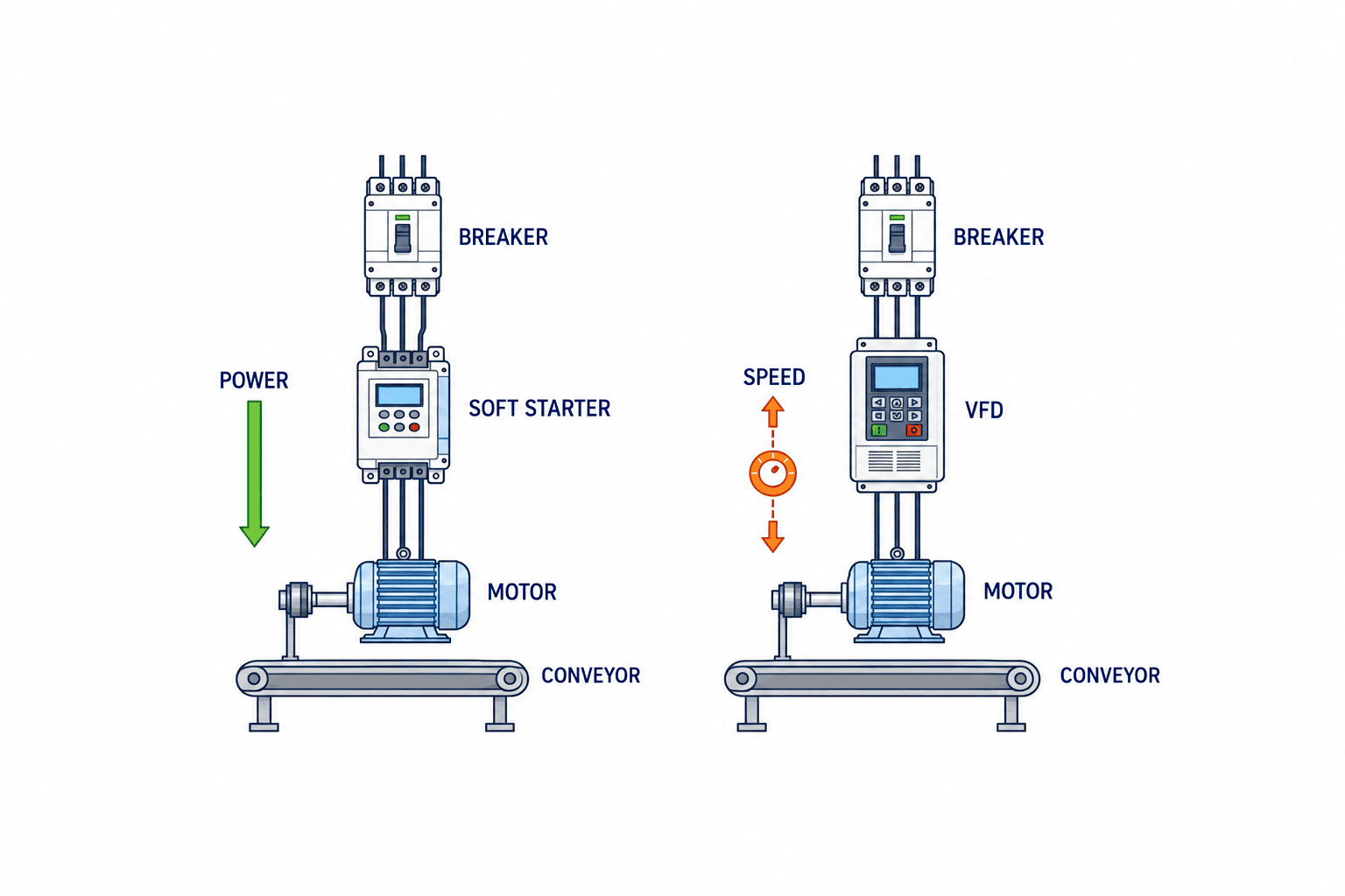
| Process requirement | Direction |
|---|---|
| Limit starting or stopping shock at constant running speed | Evaluate a soft starter |
| Control operating speed continuously | Evaluate a VFD |
| Frequent restarts or high initial torque | Verify the load curve and thermal duty for each candidate |
| Restart after a power interruption | Define safe interlocks and operator reset before selecting automatic behavior |
2. Record motor FLA before choosing a kW class
Motors with the same output kW can have different nameplate currents because voltage, efficiency, power factor and design differ. Capture the motor’s rated voltage, FLA, frequency, connection, model and nameplate photo. Record actual supply voltage and tolerance, prospective short-circuit current, existing breaker, cable size and length, cabinet dimensions and internal temperature. A candidate’s catalogue kW indication is conditional; compare its rated current and application duty with the real motor. For an external bypass contactor in a specified ATS48 arrangement, Schneider Electric’s FAQ uses motor FLA as the sizing basis. This is a model-specific reference, not a universal wiring rule.
If a plate is unreadable, identify the uncertainty and inspect maintenance records, drawings and the installed motor. Do not turn an estimated kW into a confirmed specification. The site survey should also record ventilation, dust, humidity, service clearance and how the production line behaves after a supply loss. Do not infer one electrical voltage or frequency from the country name alone; verify the actual plant supply.
3. Evaluate current limit and starting torque together
Reducing current limit can reduce available acceleration torque and lengthen the start. A pump’s valve position and retained pressure, a loaded conveyor’s starting position and a fan’s inertia can change the requirement substantially. Give the vendor the worst credible operating state, not only a no-load trial. The Schneider ATS22 current-limit FAQ says its settings are tuned to load demand during commissioning. Its published range and default belong to ATS22 and must not be applied as a universal setting.
Record three-phase starting current, acceleration time, supply voltage dip, mechanical vibration, pressure response and starter and motor temperature. A lower peak current is not a success if the conveyor stalls or pump performance fails. Stop ramp settings should be judged against actual backflow, valve movement and water-hammer behavior where relevant.
4. Size for the worst starting duty and thermal conditions
Ask for normal starts per hour, the maximum cluster of restarts, rest time, a failed-start retry, shift changes and power-restoration behavior. Continuous running current alone cannot demonstrate that the semiconductor and motor can tolerate repeated starts. Heavy-duty selection may require a different frame or model, but there is no reliable universal multiplier. Use the relevant manufacturer selection method, such as the Siemens SIRIUS catalogue or ABB selection tools, with documented input assumptions.
Check cabinet heat, mounting clearances, ventilation and ambient derating. A bypass path can reduce losses during normal running but does not erase heat generated during starting. Keep the calculation inputs, selected model, document revision and actual commissioning results so that a future production change can be reviewed.
5. Specify internal or external bypass as an electrical circuit
A bypass carries current around the power semiconductors after the start. Internal and external arrangements differ by product. State the bypass type, switching sequence, contactor rating, line isolation, auxiliary-contact interlock, fault behavior and where overload current remains measured. Schneider Electric’s ATS48 bypass FAQ describes considerations for a particular open-starter configuration; its circuit should not be copied to another model without its manual.
Draw current paths for starting, running, stopping and contactor mismatch. Confirm that motor overload protection is still effective while bypass is active. If manual bypass is offered for maintenance, define safe lockout and prevent unexpected restart. A brochure phrase such as “bypass included” is insufficient for the bill of materials or FAT.

6. Coordinate short-circuit and overload protection
The starter, upstream short-circuit protective device, line contactor, cables and motor protection form one feeder. Check the site short-circuit level, breaking capacity and the manufacturer’s tested coordination combination. ABB lists a coordination table tool covering short-circuit protection, overload protection and line contactors. Request the actual single-line diagram and the candidate model combination table.
Clarify whether overload protection is in the starter or external, and where it senses current during bypass. Check phase loss, earth-fault coverage and the restart procedure after a trip. Our motor protection breaker guide covers the breaker itself; this project also needs feeder-level coordination. Where selective tripping with upstream boards is required, use the plant’s protection study rather than catalogue assumptions.
7. Define PLC signals, faults and safety behavior
List commands and feedback: start, starting, running, bypass active, fault and local/remote mode. The exact available signals depend on the chosen model and options. If diagnostics require fieldbus communications, specify protocol, data map, loss-of-communications behavior and local authority. A general “fault” light should lead operators to a defined inspection and reset procedure.
Do not rely solely on a normal soft-stop command for emergency stop. Design the safety function from the machine risk assessment and verify it separately. Test retained run requests after PLC reboot or power return, and interlocks with valves, upstream conveyors and downstream machines. If a VFD is considered, our inverter EMC filter guide supports that separate design decision.
8. Compare vendors on the same documented assumptions
Use a comparison sheet with nameplate FLA, supply and short-circuit data, load type and initial torque, acceleration, starts per hour, peak restarts, ambient temperature, bypass and protection scheme, I/O and acceptance criteria. Siemens’ product portal and ABB’s selection and coordination tools are useful starting points. Preserve the inputs and document revision alongside each output.
Compare full delivered scope: starter, panel modifications, protection devices, wiring, installation, commissioning, training and spares. Record exact model, availability, local service and warranty. A starter-only price and a complete installed system price are not directly comparable. An alternative product should show how it meets the same duty and FAT/SAT conditions.
9. Write an RFP with measurable requirements
The RFP should state the process problem, installed equipment boundary, motor data, operating scenarios, electrical supply, protective coordination, I/O, cabinet environment and deliverables. Distinguish a fully loaded conveyor from an empty one, and a pump at its normal operating condition from a dry or unloaded trial. State measurable acceptance conditions: successful start under an agreed load, recorded current and acceleration time, required PLC alarm and restart inhibition, bypass and overload behavior, and drawings matching the installed panel.
Set numerical limits from the actual equipment and manufacturer confirmation. Do not paste a generic current multiple or ramp time into every project. Request single-line and control drawings, layout, bill of materials, thermal and coordination evidence, parameter backup, FAT/SAT procedures and service instructions in a language the local maintenance team can use.
10. Use FAT to verify the panel and control functions
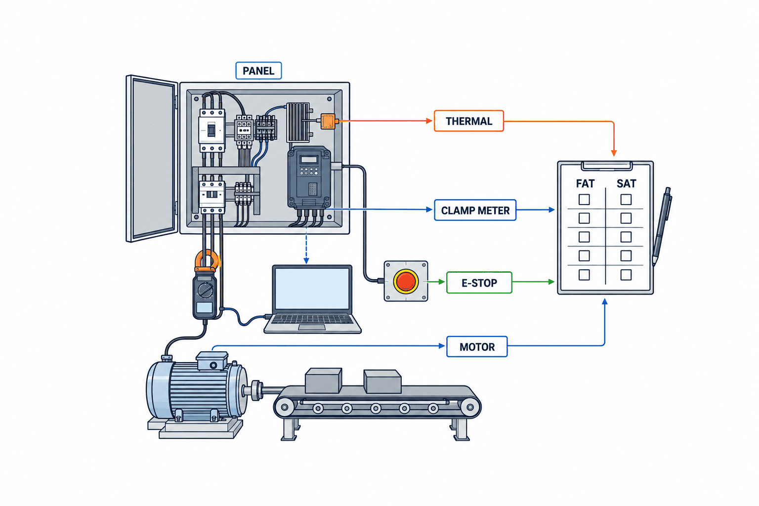
At factory acceptance test, inspect model numbers, wiring, terminals, grounding, I/O, interlocks, alarms, bypass sequence, simulated faults and parameter backup and restore. Document the scope of insulation tests so connected electronics are protected. If the real motor and load are unavailable at FAT, mark load-start performance as untested and carry it explicitly into SAT. Save the meter identity, software and parameter versions, measured results and witness names.
Check trip indication on PLC/HMI, line contactor opening and deliberate reset after the fault is understood. Test emergency-stop behavior according to the machine safety design, separately from normal stop. Include plausible loss-of-communications and power-return states. A passed no-load FAT establishes panel function, not proof of field performance.
11. Use SAT to test the actual load and duty
Before energizing, confirm motor direction, valves, belt and workpiece condition, protection settings, safety devices and access control. Run staged tests up to the agreed difficult load. Record three-phase current, acceleration time, supply voltage dip, mechanical behavior, temperature, bypass action and stop behavior. Include the expected restart sequence after adequate rest and any realistic fault recovery scenario.
If the result misses the target, inspect load condition, supply, wiring, motor data and protection before changing current limit. Record every parameter change and compare before and after under equivalent conditions. Where peak production load cannot be reproduced during SAT, identify that open condition and plan observation after production begins.
12. Common mistakes
- Ordering by kW alone: retain the motor FLA and actual starting duty with the quotation.
- Minimizing current at all costs: verify torque, acceleration time and thermal effect together.
- Assuming bypass preserves every protection feature: verify sensing and the actual circuit.
- Giving only average starts per hour: include the worst restart cluster and rest times.
- Treating FAT as a loaded-site test: carry untested performance to SAT.
- Expecting continuous speed control: choose a VFD when the process requires it.
13. Application details for pump, conveyor and fan
For a pump, provide the pump curve, normal operating point, starting valve position, retained pressure and check-valve behavior. Verify any soft-stop benefit by observing pressure and valve movement; electrical ramping cannot automatically cure a piping defect. For a conveyor, specify maximum load, incline, gearbox and restart position. Observe product stability and belt slip alongside electrical data. For a fan, collect inertia, damper position and possible residual or reverse rotation. On a shared bus, consider simultaneous starts and the upstream voltage response. These are distinct load cases even when motor kW is identical.
14. Retrofit boundaries in an existing cabinet
An empty space in a cabinet is not proof of a suitable installation. Verify cable route and bending, terminal access, ventilation clearance, door opening, maintenance removal and separation between power and control wiring. Trace the existing direct-on-line circuit, protection relay, line contactor and emergency-stop path before changing them. Check as-built wiring against drawings while de-energized. Define contractor responsibility, outage duration, rollback and post-installation electrical tests. Follow equipment instructions for insulation testing so electronics are not damaged.
15. Maintenance and change control after handover
Hand over the final drawings, protection settings, parameter file, FAT/SAT results and fault-response instructions. Identify spare model and lead time, and how a replacement device receives the approved configuration. When workpiece weight, starts per hour, pump duty or ventilation changes, reassess the selection and record current, time, temperature and product quality before and after. Standardize survey and test forms across lines, but do not copy one line’s settings to another without checking its motor and load.
16. Decision procedure when selection data are incomplete
At the first selection meeting, decide whether the project has enough evidence to select a model. The equipment team brings load and process data, electrical engineers bring supply and protection data, controls engineers bring PLC and safety requirements, and maintenance brings restart frequency and fault history. Record every missing field and whether it affects current rating, starting torque, thermal duty, protection or acceptance. Unknown nameplate FLA prevents a firm current rating; unknown maximum-load restart conditions prevent a firm torque and thermal assessment. Assign an owner and due date to each gap.
Compare at least two candidates under identical assumptions. Ask whether each starts the specified load, withstands worst restart clusters, has a documented protective-device combination, fits the existing cabinet and can be replaced locally. One candidate may have adequate continuous current but insufficient starting duty; another may need an external bypass or a larger enclosure. Include those additions in the cost and outage comparison. Preserve why a product was accepted or rejected, rather than listing only a model name.
If a torque curve is unavailable, combine equipment-maker data, measurements on the existing installation and an agreed loaded trial. Record measurement location and actual workpiece load. A manufacturer’s application review should identify the exact model and assumptions. If engineering assumptions remain, state them openly and turn them into SAT conditions that can be disproved by measurement. Separate work boundaries for power wiring, controls and safety. Name the party responsible for existing cable removal, protection settings and PLC changes.
Define each acceptance item as a measured value, method, load state and person authorized to set the limit. For starting current, define instrument sampling and peak interpretation; for temperature, sensor position and run duration; for product slip, the observation method. Before signoff, verify that the latest selection result and manual match the installed model. After production begins, watch starting frequency, repeated trips and cabinet temperature, especially if SAT could not reproduce maximum load. Keep the missing-load test open with an owner and date.
Keep raw current traces and temperature data with the approved parameter revision, not only a checked pass box. If maintenance later reports a failed start, these records allow comparison of load, supply voltage and ambient temperature. Before relaxing a limit after repeated failures, inspect mechanical drag, belt and valve condition, phase loss, terminals and supply dip. Do not bypass protection simply to keep production running. Give the manufacturer the nameplate, circuit, settings, fault log and current trace together. Handover should demonstrate that local maintenance can read alarms, isolate power safely and restore approved settings.
17. Three site cases that turn selection into test conditions
Case A: Replacing a pump starter
Suppose a direct-on-line pump start shakes the pipework. Record when vibration occurs, how the check valve moves and whether flow reverses on stopping. The electrical team gathers nameplate FLA, existing breaker, supply, cabinet space and short-circuit data. Maintenance separates routine starts from repeated starts after inspection. Put these inputs on one survey form so “reduce shock” becomes a test of pressure and vibration alongside current and acceleration time. A soft stop cannot automatically correct a stuck valve or poor pipe support. The RFP must specify whether the pump is full or empty, valve position, pressure measurement point and unacceptable stop behavior. FAT checks logic and protection; SAT observes the real duty. Do not declare an untested field condition passed at FAT.
Case B: Restarting a loaded conveyor
A conveyor that stops with products on the belt must restart from that actual position. Empty-belt data do not represent maximum load, incline, tension, gearbox resistance or product slip. A low current limit may leave insufficient torque, prolonging the start and raising heat. A higher current may start the belt but damage or displace products. Record current, acceleration time and product position for the same start. Specify that restart after an emergency stop occurs only after safety checks, downstream equipment readiness and acceptable product condition. Machine safety follows the risk assessment. Simulate interlocks in FAT and test real product and neighboring equipment in SAT. If maximum production load is unavailable, assign a later verification date.
Case C: Retrofitting a fan in an existing panel
For a high-inertia fan, existing cabinet heat and access can limit the choice as much as starter current. Inspect temperature with the door closed, airflow path, device clearance, cable termination bends and replacement space. Long acceleration may exceed a device’s starting duty even if continuous current is acceptable. When fans start on one bus, measure aggregate voltage dip and upstream protection behavior. Compare the installed contactors and cables with the drawings while de-energized. List what remains, what changes and which PLC signals are revised; agree outage and rollback. FAT verifies the panel, while SAT tests ventilation and thermal margin under real starts. Recheck when seasonal ambient or shift load changes.
These cases share one rule: a single kW table cannot settle the selection. Put electrical inputs, worst mechanical conditions, process acceptance, protection and installation constraints in one record, and keep every open assumption visible. Match each candidate to site measurements and manufacturer evidence so the quotation and acceptance test use the same basis.
18. Frequently asked questions
Can I match soft-starter kW to motor kW?
Only as a preliminary catalogue guide. Confirm nameplate FLA, supply, starting torque, time, frequency of starts and ambient derating using the selected model’s method.
What is the difference from a VFD?
A soft starter shapes the start and possibly the stop, while a VFD can control speed during normal running. Choose from the process requirement.
Is a bypass contactor mandatory?
It depends on whether the selected model has an internal bypass and the chosen wiring scheme. Document rating, sequence and protective sensing.
What belongs in FAT versus SAT?
FAT verifies the built panel and logic before shipment. SAT verifies the installed feeder with real load, plant supply and neighboring equipment.
Conclusion
First decide whether the process needs continuous speed control. Then select a soft starter from motor nameplate FLA, the worst load and restart duty, cabinet temperature, bypass design and coordinated feeder protection. Compare candidates under the same assumptions. Put measurable acceptance criteria in the RFP, verify panel functions at FAT and actual loaded performance at SAT, and assign an owner and date to every open condition.
Ask TOMAS TECH to structure the selection
TOMAS TECH supports Thai factories with control panel design, electrical design and equipment integration from site survey and RFP through FAT and SAT. Share the motor nameplate, existing diagram, start frequency and difficult operating state so we can identify missing data and a practical verification plan. Contact us.
Primary manufacturer references
- Siemens SIRIUS soft starter product catalogue
- Siemens SiePortal soft starter selection
- ABB Softstarter software and tools
- Schneider Electric: soft starter and VFD differences
- Schneider Electric: ATS22 current limit
- Schneider Electric: ATS48 bypass contactor
Product-specific settings and circuit examples can change. Use the current manual for the exact model and region before implementation.


