


Selecting a motor protection circuit breaker (MPCB) from motor power alone can lead to nuisance trips during starting, inadequate overload protection, insufficient short-circuit breaking capacity, or an unverified combination with the contactor. This guide is for purchasing, engineering, and maintenance teams commissioning or modifying control panels in Thailand. It turns motor nameplate data, starting conditions, fault-current information, manufacturer coordination tables, site conditions, and test records into a comparable procurement specification.
Define the protected equipment and circuit boundary before selecting an MPCB
An MPCB is also called a manual motor starter or manual motor protector. ABB describes its manual motor starters as devices for manual switching and protection against short circuit, overload, and phase failure. The functions available in a particular installation still depend on the exact product, approvals, and circuit. Read its data sheet rather than treating the name MPCB as a complete specification.
For a typical direct-on-line branch, draw the sequence from supply to load: upstream protective device, MPCB, contactor, and motor. The MPCB protects the motor branch; the contactor performs command-driven switching. The panel main switch, branch wiring, emergency stop, machine safety functions, and earthing each require separate design work. Installing an MPCB does not by itself establish the short-circuit rating of the complete panel or validate a safety function. Our control-panel design guide covers that broader design boundary; this article focuses on one motor branch.
List the faults to be addressed. Short-circuit protection must interrupt a major fault current. Overload protection addresses motor heating caused by sustained excess current. Phase-failure response addresses abnormal three-phase operation. A stalled shaft, damaged cable, moisture ingress, and insulation deterioration can produce overlapping symptoms; a single detection method should not be assumed to diagnose all of them. If winding temperature monitoring, earth-fault protection, or condition monitoring is required, state each as a separate requirement. Define the displayed trip cause and the conditions for resetting equipment as well as the device type.
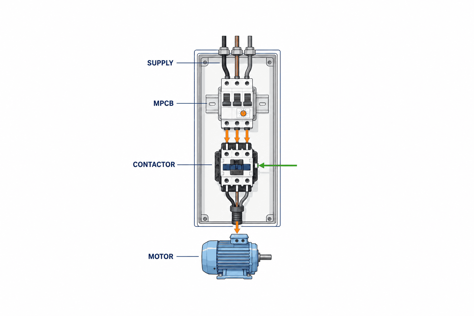
Start from the nameplate current; use kW tables only to find candidates
Collect a photograph of the motor nameplate, manufacturer and model, rated voltage, number of phases, frequency, rated current, connection, and duty. For an existing machine, compare the physical motor with drawings and the purchasing register. Record a planned future replacement as a separate design case rather than blending it into the current rating. Do not turn an estimated current calculated from kW into the final setting when the motor current is unknown.
The Siemens SIRIUS IC 10 catalog explains that running, starting, and peak currents differ even among motors with the same power. Its power-based selection values are guidance; actual motor rating and starting data take precedence. Schneider Electric’s MPCB selection material likewise refers to motor full-load current, ambient temperature, and starting characteristics. That page concerns ATEX equipment, so use it to understand the method, not to copy its product table into an ordinary application.
If a hypothetical nameplate shows 11 A, look for an adjustable range that includes 11 A. This is an illustration, not a current value shared by motors of a particular kW rating. Check whether the actual dial can be set to the motor current, whether that point is close to the limit of the adjustment range, and whether voltage, frequency, connection, and mounting are suitable. The normal starting point for the setting is the nameplate current, subject to the chosen product instructions and motor manufacturer’s requirements. Before increasing a setting to suppress nuisance trips, investigate the starting waveform, mechanical load, stalled equipment, lost phase, and ambient temperature.
| Input to confirm | Why it matters | Evidence to attach to the RFQ |
|---|---|---|
| Rated current, voltage, and frequency | Starting point for the thermal setting range | Nameplate photograph and model data |
| Starting method and duration | Assess trips during starting | Start sequence and measured waveform or maker data |
| Load and duty cycle | Distinguish frequent and difficult starts | Cycle diagram and operating records |
| Supply and earthing system | Affects applicable voltage and fault conditions | Single-line diagram and electrical-team confirmation |
| Location and panel temperature | Check ratings and correction conditions | Panel layout, ambient conditions, measurement plan |
Check thermal setting, instantaneous trip, and starting characteristic separately
The thermal function addresses sustained overcurrent and motor heating; the magnetic instantaneous function addresses high fault current such as a short circuit. Describing both only as the “breaker amperage” obscures what happens during motor starting. Some models have fixed instantaneous values, others offer adjustment, and their trip curves differ. Put the expected starting current and duration, the motor’s permissible characteristic, and conductor protection requirements against the selected device’s time-current curve.
Direct-on-line, star-delta, soft-starter, and variable-frequency-drive circuits do not produce identical currents or require identical combinations. Do not place a device chosen for a direct-on-line branch mechanically at a drive’s input or output. Check the drive manufacturer’s specified upstream protective devices, electromagnetic-compatibility conditions, output-side switching limits, and motor protection functions first. For a soft starter, check starting time, bypass arrangement, and built-in protection. If two devices provide overlapping protection, identify each one’s role and the owner of its settings on the drawings.
For a difficult start, upsizing the device is not the only response. Check whether measured starting time has grown, the machine starts under unexpected load, the supply voltage falls, or mechanical resistance has increased. Compare the product trip class and curve with the motor’s thermal limits, using a manufacturer-approved combination. After any setting change that allows the motor to start, confirm that overload protection remains effective. Record old and new settings, reason, measurement conditions, and approver so the evidence survives field adjustments.
Compare breaking capacity with fault current at the installation point
A catalog’s highest breaking-capacity figure alone does not show suitability. Compare supply voltage, available short-circuit current, upstream protection conditions, and applicable standards or approvals on the same basis. If transformer capacity or impedance, feeder length, or upstream-device information is missing, assign the fault-current calculation and its due date. Guessing that the factory distribution board is acceptable is especially risky when a panel is moved to another supply.
Data sheets may show Icu, Ics, and conditional short-circuit ratings. Identify which definition the project requires. The rating of a single breaker, the coordination rating of a starter with its contactor, and the withstand rating of the complete control panel are different claims. A manufacturer’s figure for one voltage, contactor, or upstream device cannot be carried into a different combination. Identify the final assembly in the applicable manufacturer’s table for the project’s market and specification.
For a retrofit in Thailand, examine both the panel incoming point and the motor branch. An incoming fault-current figure without the branch and upstream assumptions does not make the assessment traceable. Compare single-line diagrams before and after the change, marking affected branches, cables, earthing, and upstream settings. Reconcile the result with the design inputs in our control-panel guide.
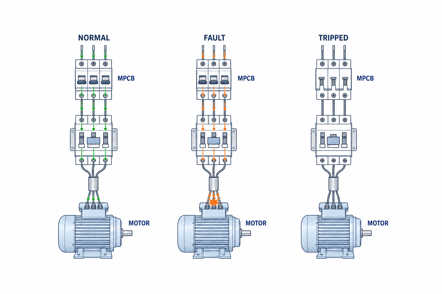
Verify the contactor combination and Type 1 or Type 2 coordination
A remotely commanded motor normally needs a contactor as well as motor protection. Contactor selection also covers operating current, utilization category, switching frequency, electrical life, and coil supply. See our magnetic-contactor selection guide for those factors. Here, the critical question is which specific MPCB–contactor combination has been tested for a fault.
IEC 60947-4-1:2023 covers electromechanical contactors and starters, including motor protective switching devices. The IEC listing includes a corrected version dated March 2026. The public scope statement alone cannot prove a product’s conformity or a combination rating; obtain the manufacturer’s certificate, data sheet, and coordination table for that purpose.
The Schneider Electric Easy TeSys coordination guide presents direct-on-line and star-delta combinations using MCCBs or fuses, thermal-magnetic motor breakers, contactors, and overload relays for Type 1 and Type 2 coordination. “Type 2” does not mean that arbitrary components can be mixed. Read the listed voltage, fault level, MPCB model, contactor model, accessories, and wiring conditions together. A mixture absent from the table does not inherit the listed result merely because its components have similar names.
| Decision | What to verify | Procurement wording |
|---|---|---|
| Coordination type | Required continuity and permitted damage after a fault | Type 1/2 target, applicable standard, table revision |
| Components | Protection, contactor, and any overload relay as one set | Maker, exact models, ranges, accessories |
| Voltage and fault level | Table conditions cover the installation | Calculation, single-line diagram, exact table row |
| After-fault response | Inspection, replacement, and reset responsibility | Maintenance procedure, spares, reset authority |
Price alone should not decide between Type 1 and Type 2. Compare the line’s recovery target, local availability of parts, maintenance skill, and inspection time after a fault. Even a Type 2 selection is not permission to re-energize without inspection. Follow the product instructions and site safety procedure after an actual fault.
Decide whether the MPCB alone provides all required protection
Possible configurations include a thermal-magnetic MPCB; an instantaneous-only protection device with a separate overload relay; or an MCCB, contactor, and overload relay. Specify which device provides short-circuit interruption, overload response, phase-failure response, switching, isolation, and maintenance disconnection. ABB discusses starters combined with contactors, and the Schneider coordination guide lists multiple arrangements. Fewer components do not necessarily mean adequate protection or easier maintenance.
Check phase-failure response by model. ABB lists phase-failure protection for its manual motor starters, but the response to imbalance, poor connections, or single-phasing depends on the particular characteristic and conditions. A separate phase or voltage monitor or winding-temperature protection may be needed for some loads. If the motor has embedded temperature sensors, state whether their signals will be used, and who will connect and test them.
Treat machine safety separately. Turning an MPCB handle, dropping a contactor, emergency stopping, and responding to a guard switch are different actions. Derive the required stop behavior and verification from the machine risk assessment. See our safety-relay selection guide, and do not describe the MPCB’s protective function as a substitute for a validated safety function.
Convert Thai factory conditions and maintenance practice into design inputs
Compare the catalog’s rating conditions with the panel’s actual conditions: ambient and internal temperature, component density, ventilation, dust, humidity, condensation, vibration, and corrosive atmosphere. Do not assume one temperature or humidity merely because the plant is in Thailand. Use site measurements, air-conditioning conditions, and the worst relevant operating case. ABB lists features such as temperature compensation, but confirm applicability to the exact model and installation.
In a retrofit, empty DIN-rail length is not enough. Check cable duct fill, bend space, operator access, distance from heat sources, upstream branch capacity, and whether operation is needed without opening the door. Auxiliary contacts, trip indication, shunt trips, and undervoltage releases add width, wiring, terminals, control-power demand, and test points. Give each accessory a defined purpose rather than adding it without a testable need.
Manage spares as approved combinations, not only a matching part number. A substitute may look and rate similarly yet have a different trip characteristic or interface. When a field replacement uses another model, update the coordination evidence and drawings and repeat setting and function checks. Record the approved configuration revision, replacement approver, and storage checks in the spare-parts list.

Ask for comparable engineering deliverables in the RFQ
If bidders receive only motor kW, each may assume different current, starting time, fault level, and coordination type. Their prices will not be comparable. Separate buyer inputs from supplier deliverables, and put an owner and due date against unresolved inputs.
| Area | Buyer supplies | Supplier submits |
|---|---|---|
| Motor | Nameplates, quantity, duty, starting data | Branch models, setting ranges, proposed settings |
| Supply | Voltage, phases, frequency, one-line drawing, fault information | Applicable voltage, breaking ratings, assumptions |
| Control | Remote commands, interlocks, stop requirements, signals | Contactor and auxiliary/trip signal diagrams |
| Coordination | Required post-fault state and market | Manufacturer table revision and row, parts list |
| Installation | Panel temperature, dimensions, density, access | Thermal and layout assumptions, panel arrangement |
| Verification | FAT/SAT scope and handover format | Tests, record templates, as-built drawings, settings list |
Include calculation and testing scope, panel shutdown time, maintenance handover, spares, and warranty in the commercial comparison. A cheap component can produce a costly change order if fault-current assessment or coordination verification is excluded. Read exclusions for short-circuit calculations, field wiring, and functional tests; assign any excluded item to a buyer-side owner and date.
Worked decision sequence: a hypothetical 11 A direct-on-line motor
This is an example of process, not a product recommendation. Assume a three-phase motor whose nameplate current is 11 A, with direct-on-line starting and remote control. Find MPCB ranges that include 11 A, then check voltage, frequency, terminals, and mounting. Obtain starting current and duration and compare them with each candidate’s time-current curve. Calculate available fault current at the supply point and verify breaking rating and upstream conditions. Choose a contactor and find the exact models, voltage, and fault level in the required Type 1 or Type 2 coordination table.
If any step lacks evidence, hold the final model choice and return the missing item to the question list. Without starting data, a setting candidate can be identified but nuisance-trip performance cannot be closed. Without fault-current information, a standalone rating does not prove panel suitability. If the combination is not in the coordination table, choose another arrangement or ask the manufacturer. “We use this model often” is not a design approval.
Use FAT and SAT to distinguish a recorded setting from proven performance
At FAT, compare the nameplate, drawings, bill of materials, and fitted product models. Record MPCB dials, contactor and accessory wiring, trip-signal display, and manual/automatic reset behavior. Follow the product instructions and panel test plan. Do not require a live short-circuit fault test on the machine: verify breaking and coordination ratings with design calculations and manufacturer documents, and perform permitted functional tests on the equipment. Record circuit ID, motor model, nameplate current, setting, date, and tester together rather than keeping an unlabelled photograph.
At SAT, confirm site supply, rotation direction, starting duration, operating current, trip history, alarm display, and reset procedure. If measurements differ from design assumptions, investigate before changing the dial and return the decision through change control. A light-load commissioning run does not demonstrate performance at full production load. When a condition cannot be tested, record the open item, future test condition, owner, and due date.
Hand over the one-line diagram, circuit drawings, bill of materials, settings list, coordination-table revision, fault-current assessment, FAT/SAT records, and rules for substitutes as one controlled package. Maintenance staff should be able to answer what tripped, why it tripped, and who can authorize a reset. Mapping circuit IDs to alarm messages in the working language of each shift helps avoid misdiagnosis.
Use the selection evidence when a fault occurs
Selection files should serve maintenance, not just purchasing. If an MPCB trips, secure and isolate the machine under the site’s procedure. An authorized person should investigate before reset. Repeatedly re-energizing to see whether it runs may worsen damage and erase useful trip evidence. Define who may release the isolation, what must be inspected, and where the record is kept.
Start by asking when it happened, under which operating condition, and which device operated first. A trip immediately at start points the investigation toward starting current, instantaneous operation, mechanical binding, or voltage drop. A trip during steady production calls for operating current, load, and overload characteristics. A trip only after long running or in a hot panel calls for internal temperature, terminal heating, mounting space, and dial settings. Simultaneous trips on several branches require inspection of the common supply and upstream coordination. These are routes for diagnosis, not conclusions from symptoms alone.
Preserve device indications, time, product and process in operation, preceding commands, motor current, voltage, ambient temperature, alarm history, and recent changes. Make the equipment safe before measurement and use qualified personnel and approved procedures. Do not create a hazardous condition simply to reproduce a trip. Link records by circuit and motor ID and compare them with previous setting changes. Identical device models on different machines are not directly comparable if loads and start conditions differ.
| Observed condition | Design evidence to open first | Field checks |
|---|---|---|
| Trip immediately on start | Start method, time-current curve, settings | Voltage drop, starting time, mechanical binding |
| Trip during steady running | Nameplate current, duty, load schedule | Measured current, process load, phase and connections |
| Trip only when hot | Panel thermal design, mounting rules | Internal temperature, terminal heat, ventilation |
| Multiple branches stop together | One-line drawing, coordination table, upstream settings | Common supply, shared load, trip sequence |
If there was a fault current, inspect the contactor, cables, terminals, contamination, and panel damage as well as the breaker. A Type 2 combination still needs post-fault inspection. If it was a nuisance trip, verify the cause and acceptable settings against maker data before raising the dial. Record whether the cause was a product defect, wrong setting, abnormal mechanical load, supply problem, or still undetermined. Do not label an unproven explanation as a permanent remedy.
Reassess the selection after expansion, replacement, or relocation
An approved model and setting are not permanent under changing plant conditions. Motor replacement, conversion to a drive, a different start method, gearbox or product changes, panel relocation, a changed transformer or upstream breaker, and extra panel heat can change the assumptions. Even a replacement motor with the same kW may have different nameplate and starting currents. Compare old and new conditions in a change-control record.
When replacing a motor, line up old and new rated current, voltage, frequency, connection, design, temperature sensors, and starting duration. Even if the new current lies inside the installed MPCB range, review instantaneous operation, starting margin, and conditions behind the coordination table. If the contactor stays, check its ratings, utilization category, coil, and tested combination. A substitute MPCB from a different series should not be assumed to have the old trip curve or coordination result.
Relocating a panel can change supply and feeder length even within one plant. Recalculate available fault current and the breaker and panel ratings. Recheck mounting, cooling, and access if ambient conditions change. In a drive retrofit, begin with the drive maker’s recommended circuit and redesign the roles of supply, switching, protection, and alarms; do not decide to retain old parts one at a time. Marking all differences between the old and new drawings makes the review more reliable.
The change approval should record the reason, affected circuit, old and new parts, supply conditions, updated fault calculation, coordination-table revision, settings, required FAT/SAT items, and as-built revision. If emergency repair uses a temporary part, state its conditions and expiry and plan the permanent replacement. Update equipment labels and electronic documents together so maintenance does not use an obsolete settings list at the next fault.
Record decisions and open items in the selection meeting
If purchasing, electrical engineering, production, and maintenance meet only to choose a part number, price and lead time can dominate before evidence is complete. First classify each design input: confirmed from nameplate, measured on site, taken from manufacturer data, calculated, or still assumed. Record source and revision. An estimated fault current or assumed start duration must not become an apparent fact.
Then compare candidates on one sheet: adjustment range, voltage, trip curve, breaking rating, contactor coordination, dimensions, accessories, spare parts, and lead time. Mark each as acceptable, conditional, or unacceptable with evidence. For a conditional choice, identify the measurement, calculation, or manufacturer answer needed and its due date. Compare price only after technical conditions are comparable. If the quoted suffix differs from the coordination-table model, ask the supplier instead of assuming a harmless naming variation.
Keep decisions separate from unresolved items in the minutes. For example: “MPCB candidate approved provisionally; formal order after fault-current calculation,” “motor maker data pending because the installed nameplate is unreadable,” or “confirm panel temperature under production load before approving the setting.” Drawing approval, purchase order, energization, and production release are distinct gates. Every open technical item needs an owner and a condition that stops the next gate from treating it as verified.
Do not close a supplier question with a verbal “no problem.” Link question ID, circuit, drawing revision provided, manufacturer’s technical answer, date, responder, and remaining conditions. Distinguish a distributor’s general advice from an answer tied to a specific model and installation. This record reveals which assumptions require review when a part becomes obsolete or supply conditions change.
Commercial comparison should also cover inspection, setting, replacement work, common spares, post-fault recovery, drawing revisions, and training. Qualitative items need not be converted into invented monetary values: compare who will do the work, when, and on what evidence. Preserve rejected candidates and reasons so a later stock shortage does not trigger an unexamined substitute. After purchasing approval, compare the delivered product suffix and accessories with the order, physical label, bill of materials, and coordination-table row. Return a mismatch to engineering before energization, including a locally sourced substitute installed by the contractor, and save the receipt inspection for maintenance.
At final approval, record not only why one candidate was chosen but also why the alternatives were rejected. A device whose adjustment range covers the nameplate current but whose starting behaviour has not been checked, one with sufficient standalone breaking capacity but no matching coordination-table entry for the specified contactor, and one that fits the enclosure but lacks verification at the expected temperature must not all be marked ‘compliant’. For each option, the electrical engineer should record the source document date, exact model, voltage, frequency, fault condition, ambient temperature and starting method. Purchasing can carry those conditions into the RFQ and apply the same comparison to substitutions. That makes it possible to see when a change in price or delivery also changes the basis of technical approval.
After installation, create an index from each panel circuit number to the motor nameplate photograph, setting sheet, applicable coordination-table row and test record. When a trip occurs, record the breaker model and setting alongside the preceding start or stop command, load, alarms, panel temperature and replacement parts. If the investigation leads to a changed setting or component, reassess short-circuit protection, overload protection, nuisance trips during starting and contactor coordination; then revise the drawings and maintenance procedure. Even during an urgent night-shift restart, state the deadline and approver for any temporary measure. Designing this record trail during selection reduces the need to reconstruct the evidence after the next expansion or fault.
Frequently asked questions about motor protection circuit breaker selection
Is an MPCB the same as a general-purpose MCB?
No. General-purpose MCB product families primarily protect circuits and wiring; MPCB families account for motor starting and overload behavior. Exact functions still depend on the model and approval. Compare the data-sheet protection functions, adjustment range, breaking rating, and conditions. Replacing an MCB with an MPCB does not remove the need to evaluate upstream equipment and the full panel.
Can the amperage be chosen from motor kW alone?
kW can narrow the candidate list, but the final setting requires actual nameplate current, starting conditions, and the selected device instructions. Voltage, efficiency, power factor, and motor design affect current. If the nameplate is unreadable, obtain the manufacturer’s model data and arrange appropriate field checks. Do not copy an estimate into the approved settings sheet.
Should the dial simply be raised when the breaker trips only on start?
First check start waveform and duration, voltage drop, load, mechanical binding, phase loss, temperature, and connections. If the trip curve does not suit the start, consider a manufacturer-approved characteristic or configuration. A higher setting may weaken overload protection; require evidence and approval for any change.
Can the same MPCB be used with a variable-frequency drive?
Do not copy a direct-on-line circuit. Current and switching conditions differ between drive input and output. Check the drive maker’s specified protective device and location, internal motor protection, and output switching restrictions; design the complete circuit around those instructions.
Does Type 2 coordination allow immediate reset after a fault?
No general permission follows from the label. Type 2 describes a tested combination under specified conditions. After a real fault, find its cause and inspect contacts, wiring, and equipment under the manufacturer’s and site’s safety procedures. First confirm that the Type 2 table row matches the installed models, voltage, and fault level.
Summary: connect nameplate, fault level, coordination, and test evidence
Motor protection circuit breaker selection does not end when a current range contains the nameplate current. Check starting waveforms against trip curves, site fault current against breaking ratings, the exact contactor combination, panel environment, trip/reset behavior, and FAT/SAT records. Approve final settings and suitability using the selected manufacturer’s documents, actual supply and load conditions, and applicable market requirements.
If your Thailand plant is preparing a motor-branch retrofit or a control-panel RFQ, contact TOMAS TECH with the nameplate, one-line diagram, starting method, and the symptom you are trying to resolve. We can help identify which measurements and documents should come first, even while the final specification is still open.


