


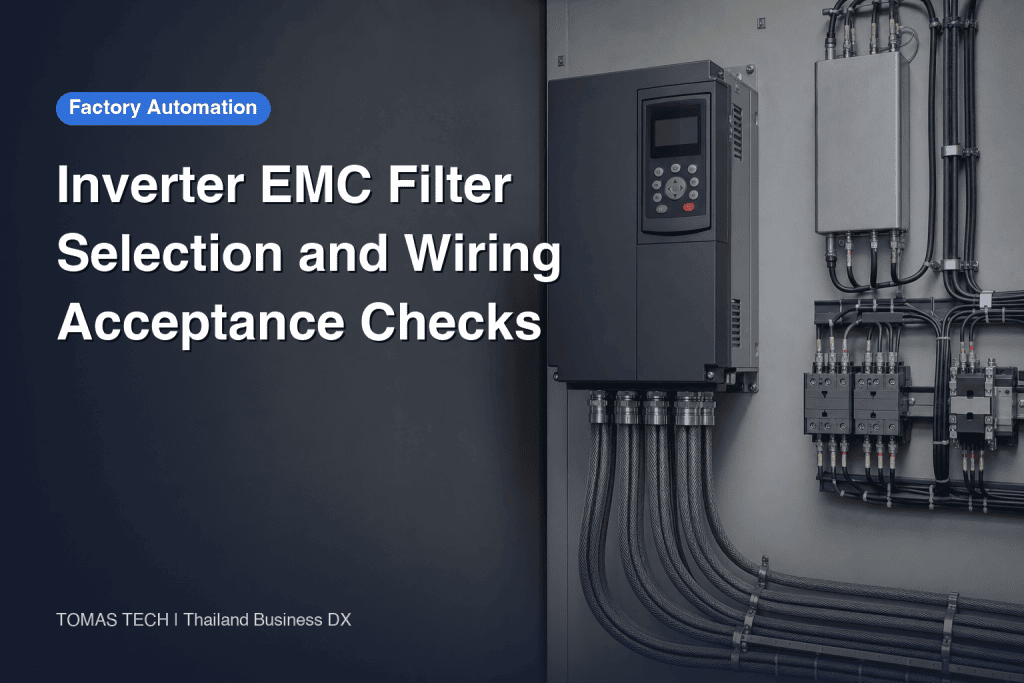
Selecting an inverter EMC filter by current rating alone can leave a factory with interference or leakage-current problems after commissioning. The practical sequence is to define the disturbance, identify its path, then verify the complete drive installation. This guide is for teams specifying or upgrading control panels in Thailand. It distinguishes a mains-side EMC/RFI filter from motor-side dV/dt and sine-wave filters and from a surge protective device (SPD), then turns those distinctions into RFP, FAT and SAT checks. Wiring, protective earthing and RCD decisions must follow the latest manual for the actual drive, the site’s supply system and applicable requirements, under a qualified electrical professional.
Define the problem before choosing an inverter noise filter
“Noise filter” can refer to several different devices. A mains-side EMC/RFI filter, either integrated in a drive or installed before it, addresses high-frequency disturbance conducted back toward the supply. An output dV/dt or sine-wave filter addresses aspects of the PWM waveform delivered through the motor cable. An SPD addresses transient overvoltage, including events associated with lightning or switching. Their locations, purposes and acceptance methods differ. TDK Electronics discusses EMC filters and output filters as different components in its technical information.
If an instrument signal becomes unstable, investigate the conducted and radiated paths, cable routing, shield terminations and panel layout. If the concern is voltage stress at a motor or a long motor lead, consult the drive maker’s output-filter guidance. If the concern is transient supply overvoltage, assess an SPD and its coordination separately. A larger filter installed without a diagnosis can increase cost, use scarce cabinet space and change leakage-current conditions while leaving the actual coupling path untouched. Record when the symptom appears, the operating state, which nearby device is affected and whether it disappears when the drive stops.

Separate input EMC/RFI, output dV/dt or sine-wave filtering, and SPD
The input EMC filter belongs between the supply and drive, or inside the drive. Its purpose is to limit relevant high-frequency conducted emissions on the supply side. A line reactor may have another purpose; neither component’s specification automatically substitutes for the other. A dV/dt filter moderates steep voltage transitions on the motor side, while a sine-wave filter is intended to make the output waveform more sinusoidal. The Danfoss VLT AutomationDrive design guide lists sine-wave, dU/dt, common-mode and harmonic filters separately and treats motor cable, EMC installation, RCD, leakage current and IT grids in their own sections.
An SPD cannot by itself demonstrate continuous high-frequency EMC performance. Conversely, the presence of an input EMC filter does not settle the plant’s surge-protection design. Put the three purposes on separate lines in the specification and bill of materials. Our related guides cover control-panel design and manufacturing and control-panel SPD selection. This separation makes it clear which supplier is responsible for each protective or filtering function.
| Device | Typical location | Main question | Evidence to request |
|---|---|---|---|
| Input EMC/RFI filter | Supply side or built into drive | Conducted disturbance and documented EMC installation | Drive/filter combination, maker’s IEC 61800-3 table, installation conditions |
| dV/dt or sine-wave filter | Between drive and motor | Output waveform and motor/cable stress | Motor and cable limits, output-filter specification |
| SPD | Selected protection point in power system | Transient overvoltage | Supply arrangement and coordinated SPD design |
Read IEC 61800-3 categories with their conditions
IEC 61800-3 concerns EMC requirements for adjustable-speed power drive systems. A C1, C2 or C3 label should not be read as an unconditional attribute of a bare drive. The manufacturer’s stated category is tied to the specified model, supply environment, integrated or external filter, motor-cable length and shielding, and installation method. Schneider Electric provides an example where the declared emission category changes with an external mains filter and motor-cable length in its electromagnetic-emission guidance. Its ATV630/650 installation-manual page is another primary reference for model-specific wiring instructions.
Two panels containing the same filter can have different disturbance paths if their cable lengths, shield bonds, input/output segregation or metalwork bonding differ. An RFP should therefore request the exact drive model and rating, supply system, intended installation environment, motor cable type and length, filter model and the manufacturer’s declared configuration. The design owner should establish the required category from the applicable market, contract and site conditions. A category name alone does not establish a blanket legal requirement for every Thai factory.
Decide whether the built-in filter is sufficient
Start with the latest manual and full product code. Confirm whether an EMC filter is actually fitted, whether it is connected for this supply system and which cable conditions support the maker’s declared result. Do not assume every model in a series has the same internal filter. Schneider Electric notes that some Altivar models do not have one, and advises checking the particular model and manual for nonstandard supply systems in its supply-system FAQ.
Consider an external filter when the maker’s documented built-in configuration does not cover the required conditions, the intended cable falls outside those conditions, or testing of the completed system indicates a need for further mitigation. Adding a filter does not automatically raise the category. Check the approved drive/filter pairing, phase count, voltage, frequency, current rating, temperature, airflow, short-circuit protection, protective earthing, distance to the drive and enclosure layout together. Fix the selected part number in the drawings and BOM. Require the same review if a supplier proposes a substitute.

Establish the supply and protective-earth arrangement first
An input filter may contain capacitors connected toward earth and therefore affect protective-conductor current. Obtain the single-line diagram, transformer secondary arrangement, earthing strategy and insulation-monitoring strategy before choosing the filter. IT, ungrounded, impedance-grounded and corner-grounded systems require model-specific attention. Schneider Electric describes the interaction of the built-in filter and IT or corner-grounded operation for certain Altivar Process drives, including the consequence of a filter-setting change for EMC performance in its IT-system guidance. That product example must not be copied as an instruction for another drive.
Protective earth supports both electrical safety and a controlled high-frequency return path. Never remove PE or arbitrarily disconnect a shield to “fix noise” or prevent RCD trips. A qualified installer must follow the actual drive’s instructions for PE continuity, panel and motor bonding, cable glands and protective-device coordination. Show the filter mounting surface, treatment of painted metal and serviceable bond points on the drawing. A temporary bench test does not prove that the installed cabinet is safe or EMC compliant.
Evaluate leakage current and RCD across the whole installation
A filter datasheet leakage-current value is useful for comparing candidates; it is not necessarily the current measured in an installed machine. TDK explains that its calculation-based value can differ from an installation measurement, which also reflects drives, shielded motor cables, motors and other connected equipment (TDK technical information). Summing catalogue numbers for several drives on one RCD is therefore not enough to declare the arrangement acceptable. Operating conditions, cable capacitance, supply quality and the measurement method matter.
RCD type, rating, circuit grouping and coordination belong to the overall safety design. The Danfoss design guide treats RCD, leakage current and IT grids separately. If an RCD trips, document the event and give the drive model, filter model, supply arrangement, cable configuration and measured conditions to a qualified engineer and the manufacturer. Do not remove the protection device or PE. Ask a supplier for the assumptions behind its RCD recommendation and a plan for verification during site acceptance.
Include motor-cable shields and panel routing in the specification
The motor cable is part of the high-frequency current path and can couple disturbance into neighboring circuits. Put the cable type, shielding, termination, gland and length required by the drive manual into the drawings. Plan separation among input power, motor output, instrumentation and communications inside the panel and along external routes. If the commissioning team moves a signal cable next to a motor output lead, the conditions used for the original selection no longer hold. The Schneider Electric ATV212 installation manual includes model-specific wiring recommendations and installation guidance.
A shield alone is not a universal cure. The panel bonding surface, route, glands and receiving instrument may also matter. Equally, a generic instruction to terminate a shield at only one end may conflict with the particular manufacturer’s EMC installation. Set the boundary between the panel builder and site electrical contractor in the RFP. Preserve photos, the as-built route, length and termination details after installation. These records shorten diagnosis when a problem appears months later.
Gather selection inputs on one shared sheet
The plant owner, panel designer, electrical contractor and drive supplier should work from the same record. Begin with the equipment and observed symptom. For a new machine, state the target EMC conditions and neighboring equipment. For an upgrade, record the affected sensor or network, the operating state and the repeatable trigger. If the path is still unknown, commission a measurement plan before committing to a component.
Add supply phase, voltage, frequency and earthing arrangement; prospective protection details; full drive and motor models; built-in filter state; motor-cable type, length and route; panel dimensions, temperature, airflow and maintenance space; and nearby instrumentation, communication and safety devices. Finally, state the acceptance tests and the change-control trigger. A change to drive model, cable length or routing should point to a named reapproval step. This sheet is an agreement on design assumptions, not merely a filter catalogue comparison.

Write RFP questions that elicit configuration and evidence
Instead of asking for “an EMC filter,” ask the supplier to identify the drive and filter product codes, whether the filter is internal or external, and the supply arrangements for which the combination is approved. Request a motor-cable and installation proposal with the relevant pages of the maker’s IEC 61800-3 documentation. Ask for leakage-current, RCD and PE assumptions, plus separate reasoning on any output filter and SPD. Require an enclosure drawing showing cable segregation, bonding, thermal space and access for inspection.
If a quotation contains only “C2 compliant,” ask precisely which hardware and installation conditions support that statement. A different drive model can invalidate the evidence even if the external filter part number stays the same. Compare bids beside price and lead time for manufacturer evidence, exclusions, site-installation responsibility and test scope. For a retrofit, decide whether the existing motor cable is being reused. If its type, length or shield condition is unknown, state that it will be confirmed by survey and list the provisional assumption in the price.
FAT: confirm that the panel matches the agreed design
Factory acceptance testing checks that the supplied drive and filter match the BOM and that the panel implements the approved drawings. Photograph the part labels, mounting location, separation of input and output wiring, shield terminations and bonding points. Include PE continuity, electrical safety and protective-device checks in the test plan according to the actual products and applicable requirements. Do not apply a generic insulation-test procedure across filter terminals without checking the maker’s instructions; agree what must be isolated and how it will be restored.
Even a powered FAT with a rotating test motor may not reproduce the customer’s supply, final cable route or nearby equipment. FAT therefore establishes the built configuration, not automatic proof of site EMC behavior. Record differences between the test and final motor, temporary and final wiring, and the operating states covered. Name the items that must be repeated at SAT, and assign an owner to every exception. If formal EMC measurements are part of the contract, define the method, place, equipment and responsible party before the order is placed.
SAT: verify the completed system under site conditions
Site acceptance testing uses the final supply, cabling, earthing and neighboring loads. Observe stopped, starting, accelerating, decelerating and normal operating states as relevant to the process. Record instrumentation values, communication errors, nearby device behavior and protective-device operation. If a symptom appears, keep the timestamp and state, then investigate mains-side, motor-side and signal-path coupling in a controlled sequence. “The problem vanished during the test” is not a durable conclusion unless the changes are recorded.
Where leakage current must be evaluated, a qualified professional should define the measurement method and limits for the complete system in advance. TDK stresses that filter catalogue values are comparison indicators and that actual system values depend on many conditions (TDK technical information). A catalogue number cannot replace site verification. The maintenance procedure should say which SAT checks to repeat after changing the drive, extending a motor cable or altering shield terminations.
Common selection errors and the better sequence
First, a sensor error is assigned to an output filter without checking the coupling path. Investigate the supply-side path, cable separation and shield terminations as well. Second, an integrated filter is treated as proof of the desired category; check the maker’s exact model, cable and installation conditions. Third, leakage current and RCD coordination are postponed until commissioning, when a panel redesign is expensive. Fourth, an SPD is specified as if it replaces EMC filtering; keep the SPD assessment separate.
Fifth, a panel that passes FAT is accepted at site without checking the final cable and neighboring equipment. Sixth, an RCD or PE connection is removed after nuisance trips. Stop and investigate safely with a qualified professional instead. The useful corrective action is linked to the measured path and the drive manufacturer’s instructions, not to a generic belief that “the filter is bad.”
For retrofits, preserve a baseline before changing equipment
On an existing line, the original cable drawing may differ from the installation. Before altering the panel, compare the drive model and settings, supply, motor, cable entries and exits, sensors and nearby networks with both the drawings and physical equipment. Record the time, speed, load and other machines running when the symptom occurs. Preserve a repeatable baseline. Replacing an old filter simply because it is old can remove a mitigation whose original purpose is undocumented.
If the existing motor cable will be reused, verify its actual route, length, shield condition, terminations and motor-side connection. A new external filter also needs a planned route between itself and the drive, thermal space and service access. Fitting in the cabinet is not proof that its installation conditions are met. Compare before and after under similar operating conditions, using observable symptoms such as instrument errors and communication faults. Those operational observations do not replace any formal EMC test required by the project. Keep the selected parts, photos, test results and remaining limitations in the as-built file.
Change control: know when selection must be revisited
A failed drive may later be replaced with another series of the same output rating. That does not establish that its integrated filter, leakage current, cable conditions or terminal arrangement are the same. A replacement approval should check the full drive model, input and output filters, supply system, protective devices and motor cable. If the maker’s documented combination changes, review the original IEC 61800-3 evidence again. A BOM note saying “equivalent allowed” cannot carry this analysis.
Extending a motor cable after moving equipment can affect output waveform, parasitic capacitance, leakage current and the maker’s EMC conditions. Moving its route beside instrumentation creates another possible coupling path. Changes to input/output segregation, shield termination, painted mounting plates or cabinet bonds also deserve review. Keep a one-page as-built record of the drive and filter models, actual cable type and length, shield termination, supply and RCD arrangement, and links to FAT and SAT results. Future maintainers can mark what changed and define a proportional retest from that evidence.
Hypothetical case: turn a packaging-line sensor fault into selection criteria
Consider an illustrative case, not a reported customer installation. A packaging conveyor is converted to variable-speed operation, after which a nearby photoelectric sensor becomes unstable. The plant team first correlates false detections with drive start and stop, speed changes and neighboring machines. If the symptom also occurs while the drive is off, attributing it solely to the drive is unsound. Even if it occurs only while running, supply-side conduction, coupling from the motor cable and pickup in sensor wiring are different possibilities. The immediate task is to identify the path, not to order an input filter.
Next, compare the as-built panel and cable route with drawings. Record the full drive model, state of its integrated filter, supply arrangement, motor-cable type, length and shield termination, plus the photoelectric sensor’s power and signal paths. Check whether input and output conductors run close together or whether a sensor cable was moved after the panel was built. These observations show whether the maker’s documented EMC configuration matches the actual site. Qualified personnel must perform electrical measurements and any wiring changes using appropriate safety procedures.
If the investigation points to the incoming supply, compare the documented integrated filter and compatible external options against the drive maker’s category and cable conditions. If the motor side is implicated, check cable route, shield and segregation and, where relevant, the output-filter conditions. A separate sensor supply defect will not be fixed merely by adding an input EMC filter. When several causes may coexist, document one change at a time and compare its effect; otherwise the contribution to noise or leakage current becomes hard to identify. The RFP can then request model-specific evidence, a site cable survey, a justified input-filter decision and an RCD impact and test plan. FAT confirms the proposed panel; SAT repeats the problematic operating state with the real sensor.
Keep decision fields in bid comparisons and acceptance records
A price-only comparison hides different design assumptions. Put the proposed drive and filter model, integrated or external configuration, maker’s supporting document, stated EMC category and conditions, motor-cable assumption, panel-work scope, leakage/RCD method and FAT/SAT ownership beside the price and schedule. Treat an empty field as awaiting an answer. A cheaper proposal that excludes replacement of an existing cable may have a different total cost and commissioning duration.
The same record needs an approver and revision history. The drive supplier should explain product compatibility; the panel designer checks placement and wiring; the site contractor checks cable route and earthing. Close FAT exceptions with a drawing revision, component change or named additional test rather than a vague “resolve on site.” After SAT, preserve the drive settings, motor, actual wiring and measurement conditions. This lets a future project assess the implications of adding a sensor or changing the drive without reconstructing the original decision from memory.
FAQ: how should a VFD EMC filter be specified?
Does an integrated filter eliminate the need for an external one?
Not necessarily. Check whether the specific model has an active integrated filter, the supply systems for which it applies, the required environment and category, and the permitted motor cable and installation conditions. If an external filter is proposed, confirm the maker-approved combination. “Built in” and “suitable for this installation” are different statements.
Which of C1, C2 or C3 applies to a Thai factory?
The country and the word “factory” alone do not determine the answer. The design owner must review the supply environment, installation location, contractual EMC target and applicable requirements, then compare those conditions with manufacturer evidence. Document why a category was selected. Do not infer a universal legal obligation in Thailand from the category label.
How should the motor-cable shield be connected?
Follow the actual drive’s installation manual and the system design. The shield termination, gland, panel and motor bonding, cable route and length form one set of conditions. Internet rules such as “one end only” or “both ends always” are not a substitute for product-specific instructions and qualified engineering.
Can the filter be disconnected if an RCD trips frequently?
Do not make that change on site without engineering review. Gather the drive and filter models, supply arrangement, cable configuration, RCD specification and measured conditions for the qualified engineer and manufacturer. Some products permit a specified internal-filter setting change in defined supply systems, but that can affect the declared EMC performance and requires a model-specific redesign.
What belongs in an EMC-filter RFP, FAT and SAT?
The RFP needs the drive, supply, cable, target conditions, filter model, manufacturer evidence and PE/RCD/leakage assumptions. FAT matches the built panel to drawings and BOM. SAT checks operation, communication and protection with the final cable and neighboring equipment. Set the measurement method, pass criteria and owner of open items before acceptance.
Conclusion: fix the target, configuration and proof before buying
Good inverter EMC filter selection begins by separating mains-side conducted disturbance, motor-side waveform concerns and transient surge protection. It then fixes the drive model, supply arrangement, motor cable and installation conditions and checks the integrated or external filter proposal against manufacturer evidence for IEC 61800-3. Evaluate leakage current, RCD and PE for the complete installation and preserve distinct FAT and SAT records. This is how a purchased filter becomes a reliable part of the finished system.
If you are updating a control panel in Thailand and know the drive model and motor-cable conditions but need to organize the input EMC-filter requirements, share your drawing and concerns through TOMAS TECH’s contact page. We can discuss the selection questions before you issue the RFP.
References
- Schneider Electric, ATV630/650 installation manual (EAV64301)
- Schneider Electric, ATV212 installation manual (S1A53832)
- Schneider Electric, Altivar Process IT-system guidance
- Schneider Electric, electromagnetic-emission guidance
- Danfoss, VLT AutomationDrive FC 302 design guide
- TDK Electronics, EMC filters technical information
- TDK Electronics, EMC laboratory


