


A factory chiller leak detection project is more than mounting a sensor on a wall. The buyer must identify the refrigerant and charge, map possible release points and airflow, decide what an alarm or detector fault must do, and prove the entire chain during acceptance. This guide is for plant engineering, maintenance, EHS and purchasing teams preparing a practical specification in Thailand. It does not claim that a US product guide or standard is Thai law. Applicable local requirements, customer rules and insurance terms must be checked for the specific site.
Fixed gas detection monitors refrigerant in room air. A handheld leak search locates the leaking component. They serve different purposes, as Danfoss explains in its 2025 guide. After a fixed monitor alarms, trained personnel follow the site procedure to make the area safe and investigate; the room monitor alone does not locate the leak. Danfoss gas detection guide
Define the boundary and purpose before requesting quotations
“Monitor the chiller room” leaves important boundaries unclear. List each chiller, circuit, service valve, pipe route, condenser, shaft and refrigerant store, and mark which areas are in scope. State whether the objective is personnel warning, early loss detection, automatic ventilation, or a combination. The required coverage, response, displays and maintenance then follow from that objective.
For each unit, reconcile nameplates, equipment records and service logs: refrigerant designation, charge, number of circuits, pressure and location. A past repair or refrigerant conversion may make the old drawing wrong. A detector specified for one gas cannot simply be called suitable for every refrigerant. Obtain current manufacturer evidence for target gas, range, cross-sensitivity, temperature, humidity and possible interference from cleaning agents or oil mist.
Safety classification and response design are refrigerant-specific. ASHRAE 34 and 15 can be design references, but their use does not by itself establish Thai legal applicability. Record the exact edition and project design basis after qualified local review rather than importing a sample alarm value. Collect room plans and sections, normal and emergency ventilation drawings, doors, pits and drains. MSA recommends reviewing each installation individually and using a smoke test to understand room airflow for its Chillgard 5000 system. Treat that as product guidance, not a universal point count. MSA routing and placement
Select a refrigerant detector against a compatibility matrix
Do not rank infrared, semiconductor, electrochemical or pellistor technology solely by a marketing label. Danfoss explains these approaches and the need to match the refrigerant and application. Request manufacturer evidence for each target refrigerant, measurement range, environmental limit, output and calibration method. If a future refrigerant change is possible, ask which sensor, calibration gas, settings and test records would have to change. Danfoss sensor technology guide
A useful matrix records refrigerant and units; sensing principle and range; point location; prealarm, alarm and fault outputs; power and wiring; calibration gas and interval; spares; environment; network/PLC interface; and a controlled maintenance bypass. Compare end-to-end response at the most distant sampling point, rather than only a sensor’s display resolution. An aspirating system adds sample line transport, bends, moisture, filters, exhaust routing and point identification. MSA advises keeping lines short, considering a water trap where condensation is possible, and applying test gas at the line end to prove response. Its line limits are specific to its equipment and must not be copied to other products. MSA routing and placement
For a point detector, check safe maintenance access and whether stored goods or new machinery might block it. Ask the supplier about warm-up, accuracy conditions, calibration stability and how the device indicates that a reading is unavailable. Give bidders the actual room cleaning and operating conditions. An unverified “equivalent gas” should not enter the purchase specification as though it were tested.
Place sensors using leak sources and airflow
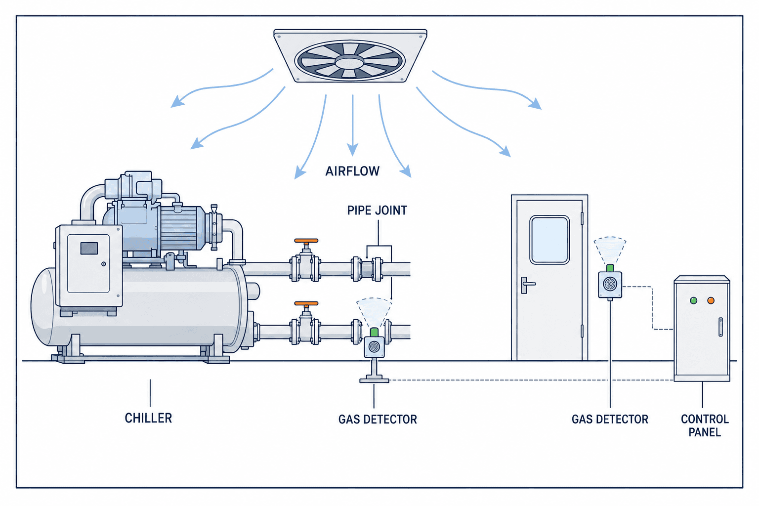
Mark pipe joints, service valves, compressor connections, heat exchanger connections and flexible sections on the layout, then overlay ventilation and worker routes. The US EPA GreenChill guide addresses commercial refrigeration rather than Thai factory chiller rules, but its discussion of field piping, leak records and maintenance is useful when making an inspection plan. Do not transfer its figures into a local legal threshold. EPA GreenChill guide
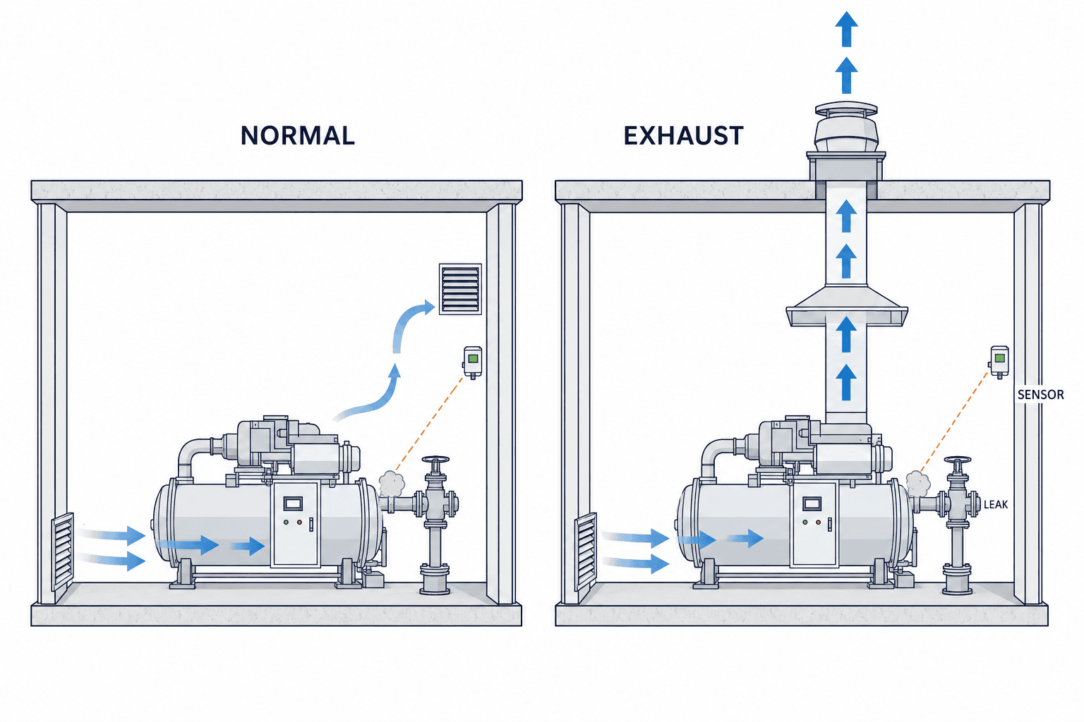
Some refrigerants tend to collect lower in a room while ammonia tends to rise, but no single installation height is right for every gas or room. Jet direction, temperature and fans affect the actual path. MSA gives product-specific floor-level sampling guidance and distinguishes ammonia; it also calls for individual analysis. Review normal ventilation, fan failure, emergency ventilation and open-door conditions. A sensor beside an exhaust outlet can miss a worker area, while supply air can push a release away from a poorly chosen point. Check condensation, washing water, access and potential obstruction. Label every point and show pipe/wire routes and panel terminals on the as-built drawing. MSA placement guide
Do not use “one sensor per chiller” as a universal rule. MSA recommends at least two monitoring points per chiller for its cited application while explicitly requiring an individual assessment. Room divisions, leak sources, air movement and the sampling cycle change the necessary count. Require every bidder to explain on a drawing which release scenarios the proposed points can capture and what remains uncovered. MSA point guidance
Separate direct gas detection from indirect operating symptoms
A fixed gas monitor directly observes refrigerant in air. Chiller pressure, temperature, current, cooling output and recharge history can suggest a problem but can also change with load, fouling, water flow or an instrument fault. Use these indirect signals to prioritize investigation, not to declare a room safe or prove a leak. Existing chiller monitoring data and cooling-water flow monitoring can help distinguish water-side and refrigerant-side operating changes. Whether a network dashboard can participate in a safety function requires a separate engineering assessment of reliability and independence.
Define a baseline operating period, the relevant load and how missing data is handled. Link refrigerant recharge, repairs and alarms to equipment IDs. EPA’s GreenChill material stresses tracking leaks and maintenance in its US commercial refrigeration context; it is not a Thai compliance test. EPA GreenChill guide
Put gas alarms, detector faults and ventilation in one cause-and-effect table
The key specification is a matrix of input state, recipient, action and reset authority. Give prealarm, main alarm, sensor fault, power loss, communications loss and calibration/bypass separate rows. If fault and gas alarm share one undifferentiated signal, operators cannot tell whether gas was detected or monitoring has stopped. MSA states that its Chillgard 5000 cannot monitor gas in a critical fault; a fault relay and designated analog fault level indicate that condition. Verify the equivalent behavior for the selected model. MSA critical faults
| State | Operator display | Pre-agreed response |
|---|---|---|
| Normal | Point value and monitoring status | Time-stamped record |
| Prealarm | Location, refrigerant, time | Check and notify |
| Main alarm | Location and site emergency instruction | Engineered ventilation/shutdown sequence |
| Fault or link loss | Monitoring unavailable | Alternative monitoring, repair escalation |
| Maintenance | Bypassed point and expected restoration | Authorization, substitute measure, return test |
Automatic fan start or chiller stop must follow an engineered risk assessment of the refrigerant, release scenario, room openings, power, fan capability and personnel movement. Starting a fan changes airflow, so detector placement and ventilation logic must be designed together. Document manual operation, fan failure, power loss and reset. A manufacturer’s example threshold is not a universal setting. Decide who receives alarms during unmanned shifts and include unit ID, location, alarm type and first safe action in the notification. Prove both message delivery and the recipient’s response procedure. Danfoss alarm/actions guidance

FAT and SAT must prove the complete function
Factory Acceptance Testing (FAT) checks a panel and software before shipment. Site Acceptance Testing (SAT) checks the installed system in the actual room. A contract must specify inputs, expected outputs, pass criteria and witnesses. At FAT, test tag/display consistency, alarm levels, fault output, communications and power loss, event history, notification, maintenance mode and reset. Identify which tests can use simulated signals and which require the manufacturer’s approved gas or response method.
At SAT, confirm actual detector positions against drawings; wire and line labels; the path from the sample point to the panel; and any fan interlock. For an aspirating system, gas applied only at the cabinet will not prove that a remote tube is clear and correctly identified. MSA describes applying calibration gas at the sample line end. Use the selected manufacturer’s safe procedure. MSA end-of-line check
Record date, point ID, test input, reading, alarm time, panel output, fan status, reset, test gas ID, witnesses and corrective work. Retest after correction and link the records. The MSA operating manual has separate sections on setup, calibration, faults, maintenance and a start-up checklist; the selected product’s current manual should shape the project test protocol. Do not create a real hazardous release for a test. If an interlock is bypassed, record approval, restoration time and proof that normal monitoring and the necessary action returned before closing the work. MSA operating manual
Maintain the monitoring function, including periods when it is unavailable
Plan calibration, bump testing, filter and sample-line inspection, and power/communication checks according to the chosen device and risk assessment. Do not copy an interval from another model. Specify test gas, tools, spares, local service capability and response time at procurement. MSA’s manual distinguishes zero and span calibration and scheduled maintenance. MSA operating manual
When a detector fails, identify the unmonitored area, relevant access, substitute measures and repair owner. Do not merely silence the indication. Notify the responsible team of a critical monitoring failure and prove response after repair. Link recharge, leak repair, calibration and alarm events by chiller ID so repeated faults can be recognized. For an OT/IoT integration, prioritize point ID, state, time, owner and closure rather than simply streaming large volumes of raw readings.
What to put in the request for proposal
Provide equipment and refrigerant inventories, room and ventilation drawings, photos, and existing panel/network conditions. Ask bidders to submit the covered and uncovered scenarios, state transitions for alarms/faults/maintenance, and FAT/SAT proof. Compare design, installation, tubing, panel changes, gas, commissioning, training and service in a common quotation template.
State the conditions in which detection is unavailable
Ask how a blocked tube, bypassed point, power loss, network loss or refrigerant conversion appears to the operator. A frozen or absent value must not masquerade as a healthy reading. Treat measurement and monitoring health as separate data. Mark unmonitored pits or outdoor equipment and define separate entry/work-permit controls for personnel who must access them.
Compare the full service cost
Include scaffolding, electrical work, fan modifications, calibration gas, spares and training, not only detector prices. For an imported device, confirm local technicians can calibrate and diagnose it and obtain replacement parts. A manual in English does not by itself guarantee an effective night-shift response. Specify what each service visit tests and which records the supplier delivers.
| RFP field | Evidence required | Comparison question |
|---|---|---|
| Refrigerant fit | Manufacturer data for each gas | What changes if refrigerant changes? |
| Placement | Tagged plan, section and airflow basis | Are blind spots and service access explicit? |
| Control | Alarm/fault/maintenance/power-loss matrix | Are fan and notification boundaries clear? |
| Testing | FAT/SAT protocol and record form | Are remote tubes and fault signals tested? |
| Maintenance | Calibration, spare parts and training plan | What happens while a point is unavailable? |
Assign approvals: engineering for chiller/fans, EHS for personnel response, IT/OT for communications and procurement for service. Revise the layout, cause-and-effect matrix, tests and training together when the design changes.
Practical questions
How many points are enough?
Room size alone cannot answer. Plot sources, ventilation, doors and pits, then show which point can capture each scenario and the expected transport/cycle time. Compare the slowest path. Explain residual blind spots; a product-specific recommendation is a starting point, not a site design.
Do IoT pressure and power data replace gas detection?
No direct measurement of room gas follows from those trends. Load, water flow, fouling and faults can create similar symptoms. Assess any proposed safety role separately; otherwise display operating symptoms and fixed gas monitoring as different signals with common timestamps and equipment IDs.
Which alarm threshold should we use?
It depends on refrigerant, hazard, detector and the project design basis. Do not copy another gas’s example value. Define the action and evidence for each prealarm and main alarm. A qualified designer and responsible site team must confirm local applicability.
Can we lower sensitivity after repeated alarms?
First investigate actual gas, cleaning agents, calibration, wiring, condensation and tubing. Record the cause and operating conditions. Any threshold change requires risk review, authorization and retesting. Silencing without a cause can hide a real event.
Who monitors while a point is calibrated?
Record who approved the bypass, the expected restoration and the substitute measure. Show the bypass locally and centrally. Before closing the job, prove gas response, clear faults and restore any necessary alarm/fan function.
Is an existing fan contact enough?
Check fan capacity, airflow path, backup power and control priorities. SAT must show command, actual fan-running feedback and failure indication. Review the existing panel and ownership boundary before pricing a retrofit.
Frequent implementation mistakes
Ordering before checking the refrigerant, aligning all detectors at the same height, testing only gas alarms, buying a “standard fan interlock” without its sequence, leaving a test bypass active and ignoring maintenance cost are recurring failures. Use the inventory, airflow drawing, fault tests, approved cause-and-effect matrix, documented restoration and life-cycle service quotation to prevent them.
Deliver the project through a controlled sequence
Survey refrigerants, room, airflow and existing signals. In basic design choose points and technology and approve the cause-and-effect matrix. Detailed design assigns tags, terminals, tubing, screen and notification text. Procurement compares gas fit and service. FAT, installation, SAT, operator training and as-built documents complete one contract scope. When replacing a live system, plan the handover so removing old sensors does not create an unmonitored gap; define temporary patrols, work owner and rollback criteria.
Manage later changes from the beginning
Reassess detection whenever a chiller, refrigerant, pipe, partition, storage rack or fan setting changes. Put “effect on refrigerant detection” into the plant modification form. A gas conversion may require sensor, calibration gas, label and threshold review. Fan changes need a fresh airflow review. Software changes must be tested against the alarm, fault, power-loss and reset matrix, with versioned backups and test records.
If the system joins an OT network, separate viewing permission from configuration rights. Define local alarm behavior when the network or server is down, and log who changes settings or bypasses a point. Train operators on the actual alarm, fault and maintenance screens and on the first safe action. Track unavailable-monitoring time, calibration completion, response delay and repeated leak locations after handover; use those observations to revise placement and procedures.
Conclusion: buy a testable monitoring function
A useful factory chiller leak detection system combines a verified refrigerant inventory, defensible placement, compatible detectors, distinct gas and fault signals, engineered fan/notification logic, FAT/SAT evidence and sustainable maintenance. Do not copy one sensor height or alarm value into every room. Require the bidder to show the placement rationale, blind spots and acceptance evidence.
For help with a Thailand plant survey, refrigerant inventory, detector/OT integration or FAT/SAT specification, contact TOMAS TECH. Sharing the equipment list and proposed refrigerants will help define the review scope.
Primary references
- Danfoss, Gas detection in refrigeration systems, Application Guide (2025).
- MSA, Chillgard 5000 Routing and Placement.
- MSA, Chillgard 5000 Critical Faults.
- MSA, Chillgard 5000 Operating Manual (2025).
- US EPA, GreenChill Best Practices Guideline (2011) — US commercial refrigeration practice, not a Thai factory compliance rule.


