


An air cylinder or solenoid valve may behave erratically even while a supply pressure gauge looks normal. Particles, oil aerosol or liquid drain can reach the equipment. Adding overly fine filters without checking flow may create a different problem: inadequate downstream pressure during a peak demand. A pneumatic line filter must be selected against the contaminant, the required air quality at a named point, actual operating flow, pressure loss, upstream drying and a workable replacement method. This guide sets out the buying and acceptance process for general industrial compressed air. Product-contact, medical and breathing-air applications require their own specialist requirements.
Define the point of use and the asset to protect
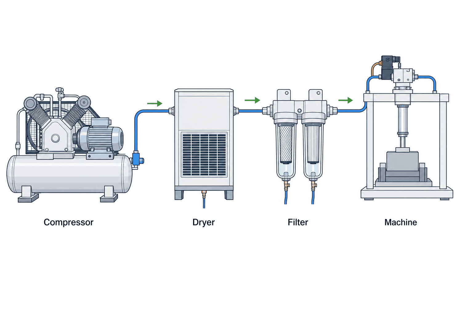
Compressor outlet, dryer outlet, main header, branch and machine inlet are different points. State where the filter will sit and where quality will be specified and measured. ISO 8573-1:2010 defines purity classes for particles, water and oil independent of the location where air is specified or measured. That does not mean measured quality will be identical at all locations. Name the sampling point in the RFP. A long downstream pipe can contribute contamination after an upstream test.
List the protected devices: cylinders, valves, vacuum generators, air blow-off nozzles and measuring instruments may have different requirements. Distinguish a branch that only drives actuators from air directed at a workpiece. Draw the compressor, dryer, receiver, main line and relevant branch. Record failures such as sticking valves, speed loss, frequent clogging and unexpected condensate. If baseline quality is unknown, commission a survey rather than assuming the source of contamination.
Separate particles, water and oil
A general particle filter, a coalescing stage for aerosols, and treatment for vapour do different jobs. Festo lists desired purity, operating conditions, contaminant type and maintenance among selection factors. Parker distinguishes particles, liquid oil, oil aerosols, oil vapour, water vapour and condensed water. A filter bowl that drains liquid water is not a dryer that removes water vapour. Check the upstream dryer and places where air cools enough for condensation to reappear. Do not use an endlessly replaced point-of-use element to hide a failed upstream drain or dryer.
Do not infer the quality at the machine from a catalogue particle rating alone. Define the requirement for each relevant contaminant and the test location. The source of oil may include more than the compressor. If the air points toward a product, the acceptable contamination must follow the process requirement rather than a generic actuator recommendation.
Use ISO classes as requirements, not as a model number
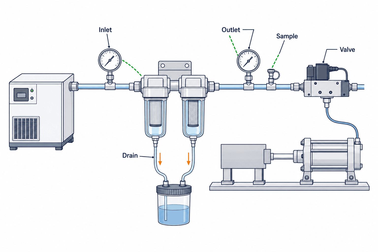
Specify the required particle, water and oil classes separately when using ISO 8573-1, along with the sampling point, operating state and test method. “ISO compliant filter” is not a comparable specification. Ask the bidder to separate element performance under catalogue test conditions from achieved quality at the stated point of use. Allow for bypass, damaged seals, expired elements and contamination introduced downstream. Provide a safe sampling port so acceptance and future troubleshooting use the same location.
Size against real flow and pressure drop
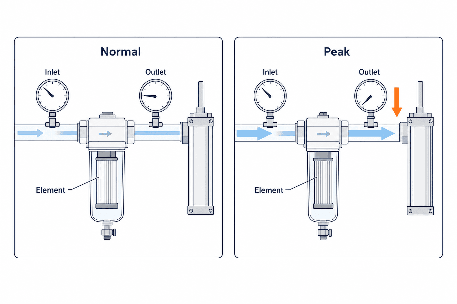
A matching pipe thread does not prove that a filter can pass a machine’s peak flow. Gather normal and simultaneous peak consumption, inlet pressure, acceptable downstream pressure and operating temperature. SMC publishes model-specific flow versus pressure-drop curves; compare candidate models at the same inlet pressure and flow instead of transferring a representative value to another product. Include the losses of serial stages, fittings and piping. Measure the machine inlet pressure under load, not only the idle gauge reading.
As particles accumulate, resistance and pressure drop can rise; Festo describes this effect. Ask for the new-element pressure drop and the service conditions under which pressure margin remains acceptable. A low differential pressure is not proof of clean outlet air. A torn element or bypass may let contamination pass with little pressure loss.
Design drainage with upstream treatment
Show the dryer, receiver and drain points on one system diagram. Decide who empties a manual drain or how an automatic drain discharges, where the liquid goes, and whether the bowl and seals suit the surrounding environment. Ensure there is room to inspect and remove the bowl. The SMC air-preparation guide notes that condensation can develop as compressed air cools through piping; a good dryer-outlet reading alone does not settle the point-of-use question.
Replace elements using more than differential pressure
Parker’s product catalogue explicitly says that differential pressure indicators are not air quality indicators or, by themselves, element service indicators. Follow the selected maker’s replacement instructions and verify required air quality separately. Record part number, replacement date, differential pressure trend, drainage and downstream faults. Provide safe isolation and depressurization before a technician opens the housing. Check local availability and lead time for replacement elements before purchase.
Keep filtration and pressure regulation distinct
A filter removes contaminants; a regulator controls set pressure. A combined FRL block still needs separate sizing of both functions. Raising a regulator setting does not necessarily compensate for a filter that has excessive loss at peak flow. Log inlet and outlet pressure under load and attribute losses to the filter, regulator and piping. For pressure selection, see our pneumatic regulator guide. For actuator demand, see our air cylinder selection guide.
Compare purchase price and operating cost separately
Compare candidates by required point-of-use quality; pressure, temperature and flow range; pressure loss under the same operating conditions; connection size; drain type; bowl and seal materials; element access; and local spare availability. If particle and coalescing stages are installed in series, include their order and upstream dryer condition. Keep the initial housing price separate from replacement elements, service shutdown and pressure-loss effects. Donaldson describes the relationship between filter performance, differential pressure and energy use, but a vendor’s case-study saving is not a prediction for a different factory. A low pressure drop is valuable only if the specified air quality is also achieved.
RFP: site inputs and the supplier’s required response
Give bidders the machine and pneumatic device models, normal and simultaneous peak flow at the machine inlet, inlet pressure and temperature, upstream dryer and existing filter arrangement, pipe diagram, existing contamination measurements, required particle/water/oil quality and the exact sampling point. If the current condition is unknown, include site investigation and measurement in the quoted scope. Provide the permissible shutdown area, service clearance, drain destination, spare-parts policy and operating hours. Space for the housing alone is insufficient if the bowl cannot later be removed.
Require a stage-by-stage proposal: product and element part numbers, purpose of each stage, inlet-quality assumptions, evidence for outlet quality, model-specific flow and pressure-drop curves at the specified inlet conditions, drain configuration, element replacement rule, replacement parts and lead times, installation plan and acceptance method. A quotation that states only a catalogue maximum flow needs clarification of its inlet pressure and permitted loss. For an “equivalent” model, recheck quality, flow, loss, materials and maintainability rather than accepting an identical thread size. Record differences in assumptions before comparing prices.
| Deliverable | What it decides | Required evidence |
|---|---|---|
| Air-quality proposal | Which contaminants meet which limit at which point | Requirement table and sampling method |
| Operating-flow proposal | Whether normal and peak demand are supported | Model-specific flow/loss curves |
| Upstream assumptions | What dryer, receiver and drain conditions are required | System diagram and inlet conditions |
| Service package | Who replaces what and when | Procedure, element codes, local lead times |
| FAT/SAT plan | How delivery is accepted at both locations | Test sheet and pass criteria |
Ask every bidder to state what is excluded. One supplier may assume a dryer in good condition while another prices a dryer repair; their filter prices are not comparable until that difference is resolved. If a measurement or site dimension cannot be fixed at quotation stage, name the responsible person, measurement date and design-freeze point.
FAT: verify the assembly and record test limits
At factory acceptance, compare housing and element codes, flow direction, stage order, drain type, gauge position, sampling port and available bowl-removal space with the drawing. Where the FAT setup can reproduce the contracted conditions, measure pressure immediately before and after the filter and at the machine inlet at the agreed normal and simultaneous peak flows. Operate representative valve, cylinder and blow-off sequences. Note which devices were active when readings were taken; idle pressure does not prove dynamic pressure performance.
For a specified purity class, use the agreed sampling point and method. A green differential-pressure indication is not a quality pass. Record instrument type, calibration, sampling duration, flow and pressure with the result. Demonstrate drain discharge and check for wrong-way installation, leakage, accessible isolation and safe residual-pressure release. Have a technician identify the element, open and reassemble the housing according to the manufacturer’s instructions, then repeat the necessary leak and function checks.
The supplier’s test air may not represent the plant compressor, dryer and long branch piping. Record that limitation explicitly. Move any untested upstream-load, drainage or point-of-use purity requirement into the SAT sheet, rather than marking it as passed by implication. Agree on corrections and retest evidence for any failed FAT item.
SAT: confirm the actual factory system
At site acceptance, repeat the checks with the real compressor, dryer, receiver, branch pipe, actual program and simultaneous consumers. Log inlet pressure, flow, filter differential pressure and machine-inlet pressure under normal and peak demand at the same time. Observe whether the selected drain handles the real duty, whether liquid accumulates abnormally, and whether leaks, vibration or service-access problems occur. A different supply state from FAT can change the result and should be documented.
If purity classes are contractual, sample at the named machine-side point, not only in the compressor room. Preserve the sampling-port photo, operating state, instrument and calibration details, measured result and pass/fail decision. Keep an as-built system diagram, initial readings, element codes, drain arrangement, service procedure and spares list. After handover, track the manufacturer’s replacement rules, pressure-loss trend, condensate and downstream faults. If clogging is frequent, inspect upstream treatment and piping instead of merely shortening the element-change interval.
Five boundaries that quotations often blur
The first boundary is between the shared supply system and the individual machine. Replacing a central filter and adding a point-of-use filter protect different spans of pipe. A receiver, the inside of a long branch, construction debris or liquid trapped in a low section may affect air after a central filter. Neither option is automatically right. Locate where contamination enters and where the quality requirement applies. If the filter belongs at the machine, include isolation, sampling and service space in the installation scope.
The second boundary is between normal and peak demand. A rated flow value must be read together with the specific model, inlet pressure and accepted pressure loss. A brief air-blow or simultaneous cylinder movement can matter if it reduces clamp force or changes cycle time. An exaggerated peak assumption can also lead to an oversized and difficult-to-maintain assembly. Use logged operation, a simultaneous-action schedule and blow-off duration to document the design flow instead of silently inventing a number.
The third boundary is between a new element and an element in service. Pressure loss can rise as a filter loads. Differential pressure alone may miss media damage or a seal fault; stable pressure alone does not excuse an abnormal drain volume. Define the initial reading, inspection method, maker’s replacement instruction and any necessary air-quality measurement. Name the person who reviews results and the action triggered by an abnormal result.
The fourth boundary is between catalogue filter performance and product or equipment quality. A manufacturer tests a component under defined conditions. Site acceptance concerns the complete assembly, including pipes, fittings, drains and changing flow. If air touches a workpiece, decide whether and where to sample near the process. Requirements in the machine maker’s instructions or the product-quality plan take precedence over a generic filter description. Where the proper measurement method is uncertain, include a competent measurement specialist in the plan.
The fifth boundary is between unit price and recovery cost. A cheap housing may require a long shutdown if the element is unavailable locally, the bowl cannot be removed without disturbing pipework, or residual pressure is hard to release. Compare the technicians, tools, isolation range and restart checks needed for replacement. Verify the spare’s storage conditions and the approval process for a changed part number. Put photographs of the installed unit and its element code into the SAT handover so maintenance staff can identify the correct spare.
A practical preselection checklist
Complete these fields before settling on a part number. If a value has not been measured, include that measurement in the site-survey scope rather than filling the gap with a guess.
| Check | Information to record | Reason |
|---|---|---|
| Protected asset and use | Actuation, blow-off, measurement or other use | Required quality varies by duty |
| Quality location | Machine inlet, tool inlet or another named point | Fixes where acceptance applies |
| Contaminants and limits | Particle, water and oil requirements | Determines treatment stages |
| Inlet conditions | Pressure, temperature and upstream treatment | Matches catalogue conditions |
| Flow | Normal and simultaneous peak demand | Tests pressure loss under load |
| Drain | Amount, discharge method and destination | Prevents operating and service problems |
| Replacement | Maker’s criteria, element and access | Sustains quality and availability |
| Acceptance | FAT/SAT sampling point and pass rule | Allows the result to be reproduced |
The first entries to settle are the protected asset and acceptance point, not the preferred filter model. Moving the sampling point later changes the requirement and potentially the warranty scope. Have the machine maker, pneumatic utilities owner, quality team and installer review the same system diagram before purchase so that responsibility at handover is clear.
Make acceptance rules more than a list of numbers
An FAT/SAT record should capture test conditions as well as target values. When recording machine-inlet pressure, note which valves were open, the sequence of cylinders and whether blow-off operated at the same time. Inlet, outlet and machine pressure readings from different moments cannot establish a transient pressure loss. Use synchronized logging or define a representative operation that can be repeated.
For purity acceptance, agree in advance on the exact sampling point, operating state and test method. Keep instrument type and calibration status, sampling duration and conditions with the result. State whether the test proves performance at the filter outlet or the quality the downstream machine actually receives. A pass at the former point does not automatically establish a pass at the latter.
Decide how to investigate a failed SAT result. Poor quality before the filter calls for an upstream investigation. A passing sample immediately after the filter but a failing sample at the machine suggests downstream piping or connections. Insufficient flow calls for review of the filter, valve, regulator and pipe path rather than a filter swap alone. A written sequence helps the supplier and plant team resolve responsibilities without unnecessary changes.
Compare a retrofit before and after using the same method
When replacing a filter because it “clogs too often”, preserve the starting condition. Collect the branch diagram, housing and element codes, installation date, differential-pressure history, drain observations, machine-inlet pressure and times of stoppages or defects. Determine whether failures affect one branch or several machines on a common header. A header-wide problem may require upstream work; a single-branch problem may point to the local pipe or operating pattern.
After the change, compare the same sampling points and representative actions under inlet conditions as similar as practical. If compressor settings or production recipes also changed, do not attribute every difference to the filter. List concurrent changes beside pressure, drain and failure observations. A low pressure drop just after installation is not sufficient if it rises rapidly; investigate upstream contamination and drainage. A sudden fall in differential pressure is also worth examining for bypass or damaged media, not automatically treating it as an improvement.
Train operators to do more than read the differential-pressure indicator: specify when to drain, how to depressurize before opening the bowl and what to check after an element change. The inspection record should have spaces for actual pressure readings, drain amount or appearance, leaks and downstream symptoms. That history supports a better capacity and upstream-treatment decision at the next machine expansion.
Frequently asked questions
Should we always choose the finest rating?
No. Match the relevant contaminant and required purity to a filter stage while checking real flow, pressure loss and maintenance. A particle rating says nothing by itself about water or oil quality.
Is naming an ISO 8573-1 class enough?
Specify the class for each contaminant, the sampling point, operating condition and method of measurement. The standard does not select a filter model for you.
Does a green differential-pressure indicator mean the element is still effective?
No. It indicates pressure behaviour, not achieved purity. Follow the selected manufacturer’s service guidance and test quality where required.
If there is a lot of drain, should we add another filter?
First inspect the upstream dryer, receiver, drains and temperature changes along the pipe. Removing liquid and removing water vapour are different tasks.
What is the minimum information for a quotation?
State the protected devices, quality and sampling point, normal and peak flow, inlet pressure, upstream treatment, allowed downstream pressure and replacement requirements.
Discuss your pneumatic line with TOMAS TECH
For new or modified automation in Thailand, share the equipment name, pneumatic diagram, compressor and dryer arrangement, symptoms, current filter part number and any flow or pressure measurements. We can help create comparable RFP and FAT/SAT criteria. Contact TOMAS TECH.


