


When selecting a pneumatic regulator, simply matching the port size and set pressure is not enough to prevent pressure drops at the moment when cylinders operate simultaneously. This article is organized for those in charge of installing or modifying automated machines at factories in Thailand, explaining how to compare supply pressure, set pressure, peak flow rate, relief, filter-integrated types, and precision types, and how to translate these into order specifications and acceptance tests. The numerical examples here are hypothetical conditions to illustrate calculation procedures. They are not guaranteed values from any specific manufacturer.
Conclusion of Pneumatic Regulator Selection: Ensure Required Pressure at the Load End
A regulator is a component that throttles the inlet compressed air and keeps the downstream pressure near the set value. However, it is not a device that unconditionally creates a constant value. If the upstream pressure is insufficient, the set value cannot be maintained, and as the flow rate increases, the downstream pressure drops due to resistance in the regulator body, filter, piping, fittings, and valves. Therefore, the acceptance criterion is not “does the pressure gauge show the set value when stationary,” but rather “does the actuator inlet never fall below the required pressure during the most demanding operation.”
There are six values to check first: ① the measured range of supply pressure, ② the pressure range required by the load, ③ normal and peak flow rates, ④ allowable pressure drop during operation, ⑤ air quality and environment, and ⑥ requirements for stopping and residual pressure release. Do not confuse maximum supply pressure with normal supply pressure, and ensure the conditions are met even on the low-pressure side. If the equipment has safety functions in its operation, conduct a separate risk assessment for the entire pneumatic circuit. ISO 4414 deals with general rules and safety requirements for pneumatic systems and components of machinery, but compliance of individual machines cannot be guaranteed by the regulator alone. Overview of ISO 4414.
| Item to Decide | Value Entered by Designer | Check at Acceptance |
|---|---|---|
| Supply Conditions | Minimum, normal, and maximum inlet pressure, temperature, air quality | Actual measurement including compressor operation cycle |
| Load Conditions | Set pressure, lower and upper limits at load end | Load end pressure during simultaneous operation |
| Flow Conditions | Normal flow rate, maximum instantaneous flow rate, duration | Waveform in actual cycle |
| Pressure Loss | Allowable drop for body and upstream/downstream piping | State when clean and before maintenance |
| Maintenance/Safety | Drainage, replacement, isolation, residual pressure check | Work procedures and abnormality tests |
At the time of ordering, use this table as an input field in the RFP, and at FAT (Factory Acceptance Test) check under simulated factory conditions, while at SAT (Site Acceptance Test) check the same items with local air supply and actual machine cycles. Rather than selecting a model based solely on rated numbers, fixing both the conditions and verification methods together will reduce post-installation issues such as “it doesn’t deliver as much force as expected.”
Supply Pressure and Set Pressure Are Different: Which Pressure Do You Measure?
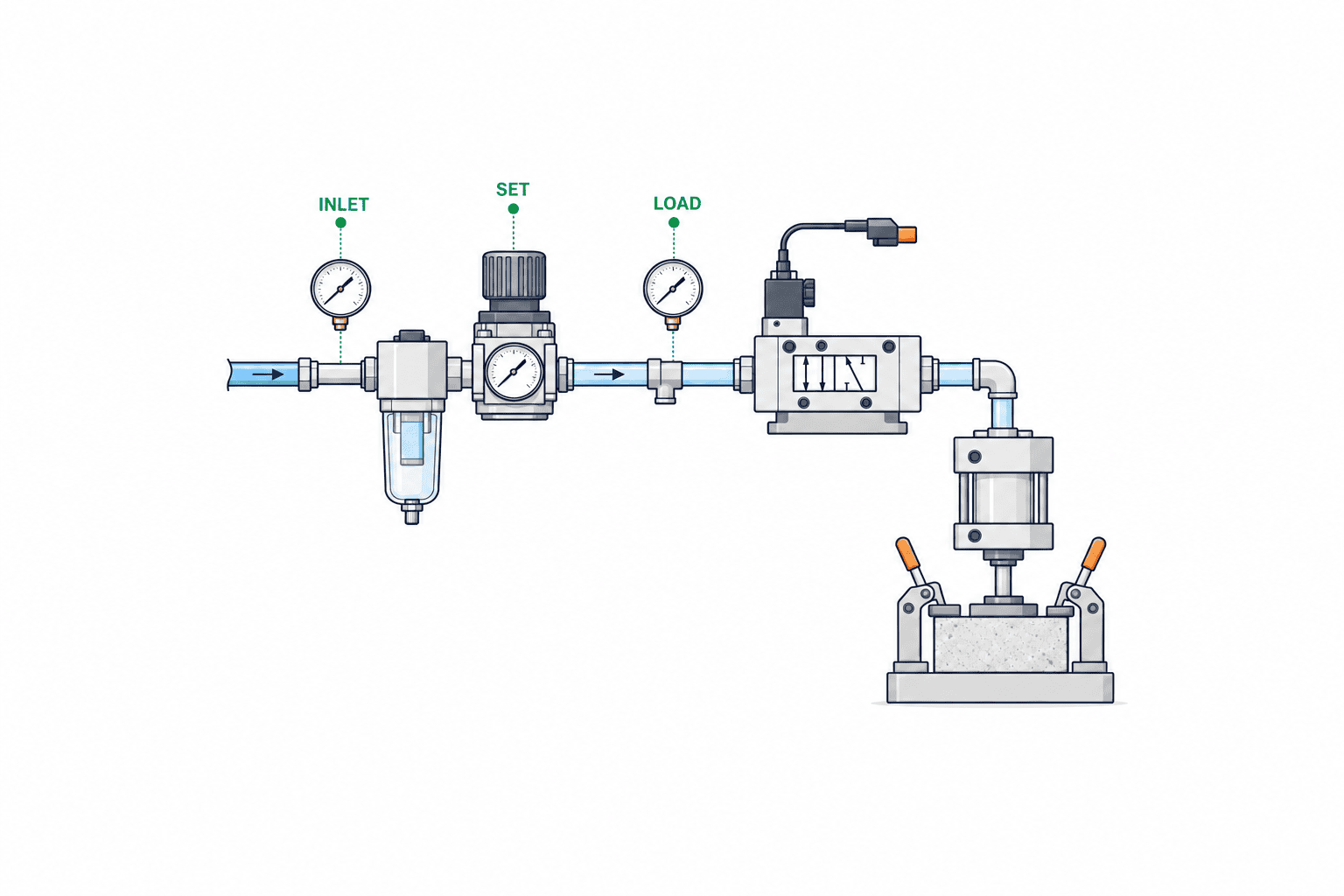
Supply pressure is the pressure at the regulator inlet, and set pressure is the target value on the secondary side. Load end pressure is the value measured at the inlet of the actual working device, such as a cylinder or gripper. The longer the piping and the more simultaneous operations, the less negligible the difference between the regulator outlet and the load end becomes. By recording pressures at three points—primary side, secondary side, and load end—it becomes easier to distinguish between supply shortage, equipment selection issues, and piping losses.
For example, in a design case where a certain clamp mechanism requires at least 0.50 MPa at the load end during operation, and a maximum loss of 0.05 MPa is expected in the piping and valves after the regulator, then at least 0.55 MPa is needed on the secondary side during operation. This 0.05 MPa is a value determined by actual measurement or design estimation, and is not a recommended value for all equipment. Furthermore, taking into account the regulator’s own drop due to flow, check on the manufacturer’s flow curve whether the secondary side can maintain 0.55 MPa even at the minimum inlet pressure. It is not sufficient to simply set 0.55 MPa when stationary.
A higher supply pressure is not always better. You must simultaneously observe the maximum operating pressure of components, hoses, bowls, pressure gauges, valves, and the allowable range of the load. Parker’s selection materials clearly state not to exceed the maximum rated primary pressure and not to connect non-designated bottled gases, among other precautions. Apply the manufacturer’s notes to the relevant product, and also check the actual medium and facility regulations. Parker Engineering Data.
Flow Rate and Pressure Drop: Don’t Choose by Port Size Alone
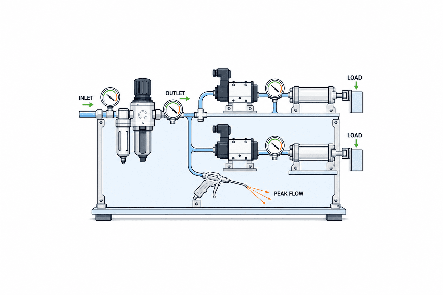
The required flow rate cannot be expressed by average air consumption alone. There are short peaks at moments when multiple cylinders advance simultaneously, when a vacuum ejector starts up, or when an air blow opens. Even if there is enough margin at steady flow, if the secondary pressure drops during peaks, it will affect positioning time, clamping force, and inspection repeatability. Conversely, if you select oversized equipment just for short peaks, you may face issues with adjustability at low flow rates and increased installation/maintenance costs.
When comparing catalog “standard flow rates,” check the primary pressure, secondary pressure, allowable pressure drop, temperature, and flow rate units used during measurement. Even if it simply says L/min, you cannot compare directly if the standards such as ANR or standard conditions differ. Festo’s precision regulator documentation annotates the measurement conditions for standard nominal flow values. Do not extract just the numbers and use them for inter-model rankings. Festo LRP Documentation.
Parker, regarding filter regulators, shows a sequence of determining the maximum flow rate, setting the allowable pressure drop at the rated flow, and selecting candidates on the flow curve. Read the curves for each primary and secondary pressure condition, and check whether the selection point meets both the required flow and allowable drop. Parker Selection Chart.
How to Determine Peak Flow Rate
For cylinders, grasp the bore, stroke, cycle time, single/double-acting volume, and number of simultaneous operations. For grippers, blowers, ejectors, etc., add each device’s manufacturer specifications and actual ON time. Simply converting volume to flow rate per minute will average out short-term peaks, so overlay the valves that open simultaneously on a timeline. Indicate the total flow during the most demanding instant in intervals of several seconds, and clearly state the reason for any margin. Rather than setting a fixed margin percentage, it is easier to review if you handle variations in consumption, future expansions, supply pressure fluctuations, and filter clogging separately.
For example, if cylinder A and cylinder B advance simultaneously for 0.4 seconds, and a blower overlaps for 0.3 seconds in the design, place the total flow rate for that overlapping period on the candidate’s flow curve. This time value is for illustrative purposes only. If piping diameter is the dominant factor, switching to a larger regulator will have little effect, and you should first improve the losses in fittings, tubes, and valves. Separate the causes by checking the pressure waveform before and after the regulator before making changes.
Distinguishing Drop and Drift
Here, “drop” refers to the phenomenon where the secondary pressure decreases as flow rate increases. Record the difference between the set pressure at rest and the pressure during operation. On the other hand, if the no-load pressure changes over time, investigate other causes such as supply fluctuations, temperature, component characteristics, or downstream leaks. Simply having an operator visually check a single pressure gauge may miss momentary drops, so if necessary, record the waveform with a measuring instrument with sufficient response speed. Include the sensor location and sampling conditions in the log.
Relief Type and Non-Relief Type: Separate from Shutoff and Exhaust Functions
A relief type regulator releases air to the atmosphere when the downstream pressure exceeds the set value, depending on the structure and conditions of the model. A non-relief type does not have this pathway, or is structured so that air is not released externally during normal pressure regulation. According to Parker’s structural explanation, when the downstream pressure of a relief type exceeds the set value, the diaphragm moves and air is discharged through the vent. Parker Engineering Data. SMC’s AW documentation also presents options for both relief and non-relief types. SMC AW Catalog.
The relief function is related to “downstream pressure adjustment when lowering the set pressure,” and is not synonymous with the safety function of exhausting the entire piping within a specified time during emergency stop. Residual pressure may remain if there are check valves, closed actuator chambers, or long downstream volumes. For emergency stops, maintenance, or power restoration, identify where residual pressure may exist on the circuit diagram, and separately design the necessary shutoff valves, exhaust valves, and pressure checks. Also confirm that cylinders do not move unintentionally during shutdown. Safety design and verification should be performed per equipment unit, considering the scope of ISO 4414. ISO 4414.
Additionally, for applications where air discharged during relief is undesirable in the work environment, or where special media, clean rooms, or control of noise and oil mist are required, confirm the exhaust path and the manufacturer’s applicable scope. SMC’s AR series documentation distinguishes model conditions such as media, maximum operating pressure, set pressure range, and relief pressure. Do not apply listed values to other series. SMC AR Catalog.
Integrated Filter Type and Standalone Type: Select Air Quality and Maintenance Together
A filter regulator is a product that integrates particle and liquid management with pressure reduction. While it saves space and reduces the number of piping points, pressure loss at that section also changes as the filter element becomes dirty. Confirm the required filtration grade, drain handling, bowl material, installation orientation, replacement space, and the positions of upstream shutoff valves and pressure gauges. SMC’s AW documentation specifies port size, set range, filtration specs, drain capacity, bowl material, etc., by model, so you must determine the full model number, including the suffix, even if the name is the same AW. SMC AW Documentation.
Especially in Thai factories, do not assume drain generation and supply quality based only on theoretical conditions such as day-night temperature and humidity differences or supply piping status—inspect the actual situation. However, condensation cannot be determined by region name alone. The situation changes depending on dryers, main line filters, piping slope, and end-use applications. For air quality required in precision measurement, food, or electronic components, work backward from the manufacturer’s requirements for the equipment used and customer specifications. It is important not to assume that installing a single integrated filter type will satisfy all contamination requirements.
When selecting a filter, set the pressure differential just before replacement as a control value, not just the clean, new state. Decide whether to replace the filter when the differential pressure reaches a specified value or on a regular schedule, using a method that can be executed on-site, and recheck the set pressure and operating pressure after maintenance. Check the notes for each model regarding transparent bowl damage, compatibility with chemicals, and drain discharge methods. Ensure not only that the unit fits in the installation space, but also that there is enough room to actually remove the bowl.
Conditions for Selecting Precision Types: Work Backward from Required Repeatability
For processes where even slight changes in secondary pressure affect quality—such as minute pressing forces, dispensing pressure, measurement jigs, or leak testing—precision regulators become candidates. Do not select a “precision” model simply because it is labeled as such compared to standard types; instead, specify allowable pressure fluctuation, hysteresis, response, flow rate, and supply quality. Festo’s LRP/LRPS documentation shows, for the relevant models, a maximum pressure hysteresis of 0.02 bar and downstream exhaust. These are specifications for that series only and are not guaranteed values for all precision types. Festo LRP/LRPS Documentation.
The important point is that even with precision types, flow rate conditions cannot be ignored. Even if excellent pressure regulation is achieved at low flow, it may not be suitable for use as-is in a main line supplying multiple large-diameter cylinders simultaneously. Compare the entire circuit: separate only the loads that require precision into dedicated branches, perform rough regulation upstream with a general type, or review air tanks and piping. Link the allowable output pressure range, stabilization time, and variation during repeated operation to the process acceptance criteria.
Comparing SMC AR’s general model documentation and Festo LRP’s precision model documentation reveals that application cannot be determined by port size or set range alone. For quotation comparisons, request curves and maintenance conditions under identical primary pressure, secondary pressure, and flow rate conditions. If the catalog does not have data under the same conditions, it is safer to ask the supplier for test conditions and not compare prices alone with missing data.
Circuit Design for Automatic Machines: Role Sharing with Sensors, Valves, and Loads
Regulators adjust pressure, solenoid valves switch flow paths, and pressure sensors detect status. Their roles are not interchangeable. You cannot prove clamp completion or workpiece holding by the position of the set knob or the pressure gauge at the regulator outlet alone. If detection is required, specify sensor location, threshold, delay, and machine behavior in case of abnormality in the control specification. For sensor selection and signal design, see the separate article Selecting Pneumatic Solenoid Valves.
The configuration of placing a single large regulator on the main line versus dividing pressure regulation by load group differs in cost, maintenance, and the scope of abnormality impact. If loads with different required pressures are grouped under a single set pressure, even loads that only need low pressure will be operated at high pressure. Conversely, if too many branches are added, the number of set points increases, leading to more misadjustments and inspection burden. Make a table of required pressures, simultaneous flow rates, operation sequence, and state at stop for each process, and separate only those branches that have a reason for independent regulation.
Even when monitoring pressure constantly with IoT, do not confuse data collection with pressure regulation. If you record the cycle, solenoid valve ON status, compressor side pressure, and blow usage state at the time when pressure drops, you can narrow down candidates for leaks or overloads. For a method of viewing both compressed air usage and power consumption of equipment, see the article Compressed Air Data Collection. This article focuses on end-point regulator selection and acceptance conditions.
Specifications to Include in the RFP: Comparing Candidates Under the Same Conditions
Assumptions to Record in the Selection Table
In the selection table, do not just record results such as “Required secondary pressure: 0.55 MPa,” but also document who derived that value from which load. The required thrust for a cylinder depends on factors such as mechanism friction, orientation, acceleration, workpiece weight, and the allowable cycle time. Simply increasing the regulator’s outlet pressure does not always solve the problem, and may even exceed the allowable pressure for the load equipment. Confirm with the mechanical designer the assumptions used in thrust calculations—such as bore, rod diameter, mechanical efficiency, and safety margins. Test the pressing force and holding with actual workpieces, and link the pressure targets to quality requirements.
Also record the units used in flow calculations. If you treat the free air flow rate converted to standard conditions, the actual volumetric flow rate in piping, the compressor’s discharge rate, and the “nominal flow rate” in component catalogs as the same figure, you may end up with candidates that are either undersized or oversized. Cite the axes, supply pressure, set pressure, and measurement standards from the catalog curves, and convert the peak values from your company’s time chart to the same standard before overlaying them. If you leave the conversion factors in your documentation, you can recalculate easily when changing model numbers later.
The minimum value for primary supply should be determined at the equipment inlet, not at the compressor room’s gauge. What matters is how much remains after passing through the main line, branches, simultaneously operating equipment, dryers, and main line filters. When recording pressure, include not only normal operation but also conditions with high air usage due to production variety or shift patterns. If the measurement record is short and the lower limit of supply is unknown, clearly state this uncertainty in the RFP and move it to items to be reconfirmed during the SAT.
Conditions That Are Easy to Overlook When Comparing Candidates
Even if the piping connection has the same nominal diameter, the internal flow path and flow curve may not match. The bowl material, presence of automatic drain, pressure gauge mounting position, lockable knob, and presence of a backflow function also vary by model suffix. As shown in SMC AW documentation, you cannot finalize specifications by series name alone. Compare the quoted model number and the drawing model number character by character, and clearly state the conditions for approving substitutes. When replacements are made on-site as “equivalent products,” at minimum, reconfirm the maximum primary pressure, adjustment range, flow curve, exhaust method, medium, and piping direction.
Include maintenance effort in your comparison. Integrated filter types can reduce the number of piping points, but may pose problems for access during element replacement or stocking of replacement parts. With standalone or filter-separated types, it may be easier to deploy to branches requiring different cleanliness levels or to partially replace components. Which is superior depends on equipment layout and maintenance structure. Make your decision based on operational costs, including the area that must be stopped for replacement work, the procedure for depressurizing, and the steps for resetting after resumption.
If a supplier responds that “pressure is stable,” clarify whether they mean variation due to static inlet pressure changes, drop during flow changes, or hysteresis when adjusting up and down. These are all grouped under the word “stable,” but the test methods differ. Quantify only the indicators that affect equipment quality, and avoid unnecessary investment in high specifications. By sharing measurement conditions, it also becomes clear which branches can use standard models and which require precision models.
In the RFP, specify not only model numbers but also the input values and submission materials that allow suppliers to respond under the same conditions. First, provide the equipment circuit diagram, load list, minimum/normal/maximum primary pressure, required secondary pressure, and a time chart of simultaneous operations. Next, specify the allowable pressure drop required for candidates, adjustment range, secondary pressure behavior in response to primary pressure and flow changes, need for relief, air quality, temperature, connection threads, installation orientation, gauge, lock, and maintenance space. When specifying a particular pressure value, always state the measurement location.
The required submissions are: model number configuration table, current manufacturer data sheet, flow curve under target conditions, pressure characteristics, filter replacement parts, recommended maintenance, external dimensions, piping direction, medium compatibility, spare parts, and delivery time. If the curve is measured only at the standard primary pressure, request evidence that it will work at your company’s minimum supply pressure. The arrangement of replacement parts and technical support within Thailand is also an evaluation item, as it directly impacts downtime.
Example: Writing Acceptance Conditions in the RFP
State, for example: “At the minimum primary pressure defined by the equipment, and at the specified maximum simultaneous operation, the load-end pressure must not fall below the equipment’s required minimum. Both parties must agree on the measurement point, instrument accuracy, and recording interval.” The specific pass/fail values are set for each piece of equipment, including load, safety requirements, and measurement error. Additionally, add items such as “stabilization time after changing the set value,” “handling of drain if present,” and “method for confirming residual pressure after shutdown.”
Next, create a quotation comparison table. Next to the price column, include columns for supporting documentation under the same conditions and for deviations. Responses that simply state “sufficient flow,” “high precision,” or “safe” cannot be judged. Evaluate proposals that specify, with numbers, curves, and test methods, which load, at what flow and inlet pressure, and how the secondary pressure will behave. If data is missing at the RFP stage, discussions about changing parts are more likely to arise after ordering.
Specific Example of Pre-Order Review
Finally, let’s consider a pre-order review using a single circuit as an example. In this scenario, the clamp cylinder and air blow of an automatic machine are supplied from the same branch, and the process involves the blow opening while the clamp is being held. The designer checks not only when the clamp starts to move, but also the load-side pressure when the blow overlaps during holding. If the pressure drops when the blow starts and the margin for holding force decreases, the designer reviews not only the regulator’s flow curve, but also the branch piping’s inner diameter, the valve’s flow characteristics, and the nozzle conditions of the blow. Simply attaching a pressure gauge at the regulator’s outlet cannot prove the pressure dip at the cylinder inlet.
To the supplier, the designer requests data not only for the usual supply pressure, but also for the minimum supply pressure observed at the equipment inlet. If the catalog curves do not include those conditions, the supplier is asked to provide the assumptions for interpolation and a test plan. Even if the initial test passes, if the margin disappears when the filter is in a pre-maintenance state, the designer decides on a management value for the replacement differential pressure or reviews the upstream air treatment. This allows for distinguishing between countermeasures that only require changing a single part number and those that involve supply and piping.
If a precision model is considered as a candidate, it is first demonstrated whether fluctuations in holding force actually affect quality. Even if the precision model has a small hysteresis value, if the pressure drops at peak flow, it is not suitable for the clamp. On the other hand, it may be suitable for another branch that controls a minute pressing force with a small amount of air. Rather than consolidating two applications with a single “high-performance” part, the necessary indicators are defined for each load.
The minutes of this review include the adopted candidates, excluded candidates and their reasons, the basis for the primary pressure, the reading points of the flow curve, conditions that can be reproduced in FAT, and conditions to be carried over to SAT. It is also checked whether the Thai maintenance staff can procure replacement parts and whether the flow direction on the drawings matches the actual equipment. To avoid repeating the same review during modifications years later, not only the calculation files but also the observation conditions that determined pass/fail are handed over.
FAT and SAT: Deciding Where to Measure After Installation
How to Record Acceptance Results
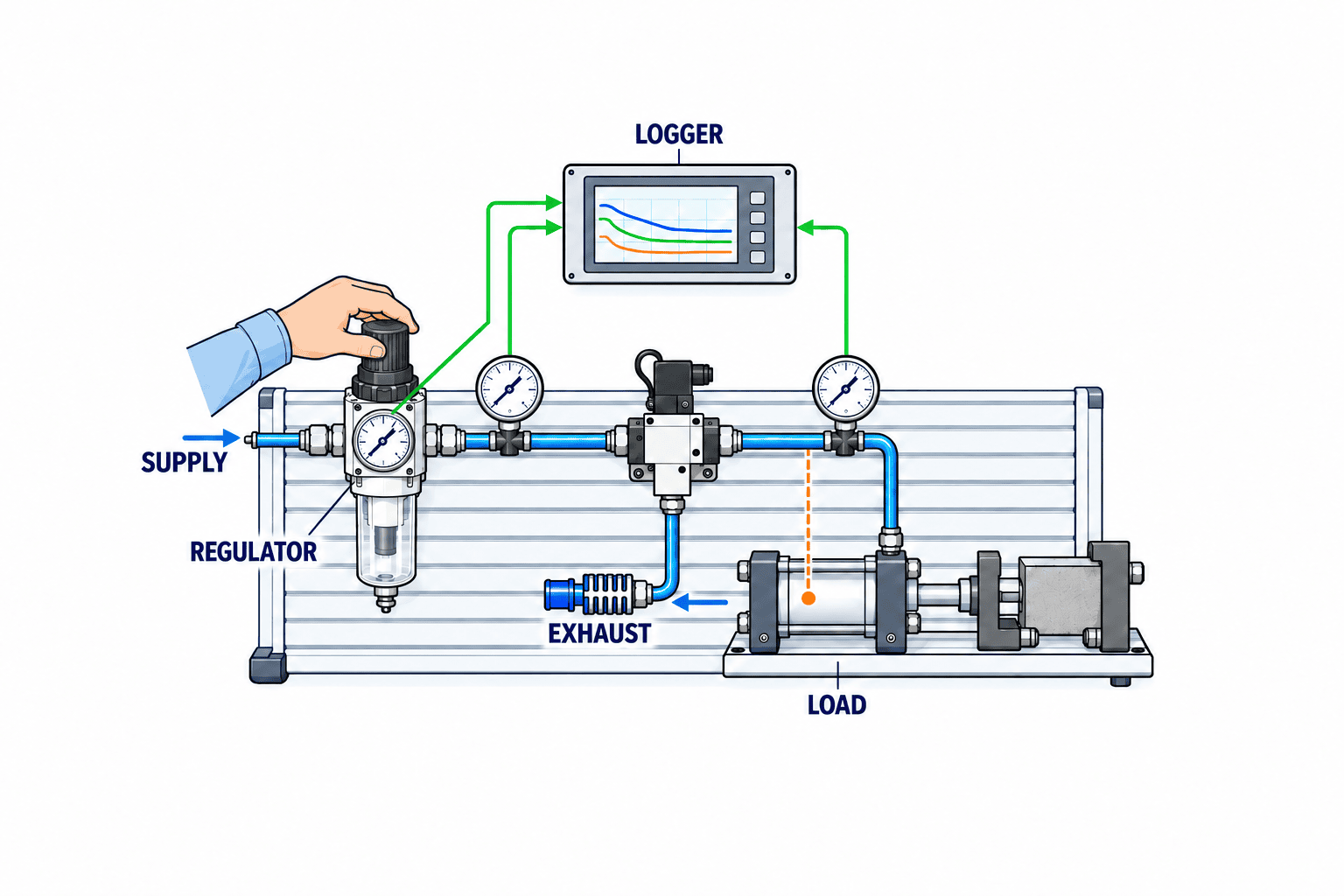
Acceptance records should include the date and time of measurement, machine number, workpiece, cycle, set pressure, supply pressure, measurement point, instrument model number, calibration status, pressure waveform, and the minimum value at maximum load. A single pass/fail line is not enough for later comparison when seasons or production varieties change. The position marked on the adjustment knob can serve as supplementary information, but should not be used as evidence of pressure. Record who made the adjustment and by what procedure it was locked, to make it easier to reproduce after maintenance.
If you only select times when the building’s compressed air source is stable for SAT testing, you may overlook severe conditions. Ask the equipment manager about times when supply changes, such as when adjacent lines start up, products that use a lot of blow air, or restarts after lunch breaks. If you cannot actually reproduce those conditions, record them as “untested conditions,” and decide on the necessary monitoring period and who will be responsible for retesting. If future expansion is assumed, separate the current acceptance from the post-expansion revalidation.
Furthermore, it is important not to decide on a single cause for failure before measurement. Symptoms that appear to be due to insufficient regulator capacity can also be caused by filter clogging, primary side pressure drop, fitting restrictions, insufficient solenoid valve flow, or cylinder leakage—all of which can cause similar delays. By recording primary, secondary, and load-end pressures simultaneously, along with valve signals and actual operation times, you can systematically trace where the pressure dropped. Record not only the replaced parts but also the waveforms under the same conditions before and after the change to confirm the effect.
The operational standards after acceptance are also deliverables of the SAT. Transfer to maintenance procedures the allowable set pressure range, abnormal alarm thresholds, filter replacement conditions, drain inspection intervals, and isolation and residual pressure confirmation points during shutdown work. If manufacturing, maintenance, and quality personnel use the same measurement points on the drawings, you can avoid discrepancies over which location is “normal” during failures. It is important to hand over the actual measured acceptance conditions, not just rely on the general descriptions in the instruction manual.
FAT (Factory Acceptance Test) is acceptance confirmation performed by the manufacturer/assembler, while SAT (Site Acceptance Test) is confirmation performed at the installation site with actual supply and load. Items that cannot be reproduced under equivalent conditions in the FAT are carried over as unverified to the SAT. Do not assume that “since it passed FAT, there is no need to measure flow and pressure on site.” In particular, building piping, simultaneous use with adjacent equipment, and long end piping only come together for the first time on site.
| Test Item | FAT Confirmation | SAT Confirmation |
|---|---|---|
| Model/Installation | Model suffix, orientation, set lock, gauge | Piping direction, maintenance space, display |
| Static Pressure | Primary/secondary setting and retention | Supply pressure low/high conditions |
| Pressure During Operation | Outlet pressure waveform at simulated peak | Load-end pressure waveform during actual cycle |
| Simultaneous Operation | Simulated worst-case timing | Lower limit confirmation with other equipment |
| Exhaust/Residual Pressure | Designed stop sequence | On-site isolation, exhaust, residual pressure check |
| Maintenance | Filter/bowl replacement procedure | Drain handling, replacement parts, operator training |
When reading pressure gauges, consider instrument error and response delay. If you are judging instantaneous drops in the SAT, use a transducer with appropriate location and response, and record timestamps and valve signals simultaneously. Decide on representative scenarios including continuous operation, cold start, stop/restart, and primary pressure drop. For product quality-related clamp force or positioning time, link not only pressure but also actual measurements.
If a test fails, first distinguish whether the regulator outlet is also low, or if only the load end is low while the outlet is maintained. For the former, check primary supply, regulator flow characteristics, and filter differential pressure. For the latter, check piping, fittings, valves, tube inner diameter, and load leakage. If the primary pressure itself periodically drops, investigate the upstream compressed air equipment and the effects of other loads. Do not rush to conclusions about replacement parts; increase measurement points and retest.
Frequently Asked Questions
Can pneumatic regulators be replaced if the port size is the same?
Whether replacement is possible is not determined by port size alone. You must compare maximum primary pressure, set range, flow curve, relief method, medium, temperature, connection thread standard, gauge and bowl materials, and mounting dimensions. For circuits related to functional safety or exhaust during stoppage, a risk assessment and retesting after changes are also required. Simply copying the secondary side set value from the old model to the new one does not guarantee dynamic pressure.
Is an additional air filter unnecessary if using an integrated filter regulator?
It depends on the required air quality and supply conditions. Compare the particle filtration, drain capacity, and pressure loss of the filter regulator with the moisture, oil, and particle requirements of the load equipment. If drying or oil removal is needed on the main line side, an integrated unit at the end point alone is insufficient. Include the differential pressure before and after filter maintenance as part of the FAT/SAT acceptance criteria.
Does a relief-type regulator eliminate residual pressure during emergency stop?
No, it does not. Relief is a secondary side pressure control function for exceeding the set pressure. Blocking/exhaust during stoppage, checking residual pressure beyond check valves or in cylinder chambers, are separate design considerations. Please evaluate the entire circuit and actual equipment to ensure there are no hazardous movements.
Can a precision regulator prevent pressure drop?
Even precision types have upper flow limits and measurement conditions. If the allowable flow is exceeded or the primary pressure is insufficient, the required secondary pressure cannot be maintained. Define the reproducibility and peak flow required for quality separately, and check both the manufacturer’s curves and actual equipment tests.
What should be prioritized for FAT/SAT at a Thai factory?
Prioritize periods of low supply pressure, processes with maximum simultaneous operation, filter condition before maintenance, onsite piping length, and residual pressure checks after stoppage. Do not set values based solely on the fact that it is in Thailand; reflect the actual measured values of that factory as assumptions in the RFP. If both Japanese and Thai facility engineers mark measurement points and acceptance criteria on the same drawing, it will reduce interpretation differences after handover.
Summary
Pneumatic regulators should be selected based on the pressure at the load end, assuming the lower limit of supply pressure and peak flow. Compare standard types, integrated filter types, precision types, and relief methods according to application, and design safety during stoppage as a separate circuit function. By aligning measurement conditions and manufacturer documentation in the RFP, and confirming pressure, operation, and maintainability with simulation in FAT and onsite measurement in SAT, you can make procurement decisions that do not rely solely on price and port size.
If you want to organize pressure drops in existing pneumatic circuits or component selection for new lines in automatic machines at Thai factories, please consult TOMAS TECH. If you have a load list, circuit diagram, and supply pressure records, we can concretely define RFP and FAT/SAT checkpoints together.
Reference Information
- Parker, Air Preparation Products Engineering Data: filter/regulator selection and flow charts
- SMC, Regulator Series AR and regulator with backflow function
- SMC, Filter Regulator Series AW
- Festo, Precision pressure regulator LRP/LRPS datasheet
- Festo, Precision pressure regulator LRP product data
- ISO, ISO 4414:2010 overview
Product specifications and standards are based on publicly available documents at the time of reference. When adopting, please check the latest documentation for the target model and the application requirements of your equipment.


