


Introduction: Three Things to Decide First in Industrial Temperature Sensor Selection
Industrial temperature sensor selection can look like a job that ends once you pick “thermocouple type K, Class 2” or “Pt100, Class A” from a catalog. On the shop floor, however, we often hear complaints such as “The catalog says Class A, yet its reading does not agree with the thermometer next to it,” “The wire broke, but 0°C or the upper-range value went straight into the records,” and “An auditor asked us to justify our calibration interval, and we could not answer.”
A word on the production environment in Thailand. According to The Star (September 30, 2026), which carried a Reuters report, Thailand’s manufacturing production index (MPI) for August 2026, released by the Ministry of Industry, rose 4.44% year on year, beating the 1.0% rise forecast in a Reuters poll. However, the director-general of the Office of Industrial Economics (OIE) explained that the MPI calculation method had been revised, adding new electronics products and changing the weights. Note that the figure cannot simply be compared with the previous year’s numbers. According to Trading Economics (September 30, 2026), the Ministry of Industry raised its 2026 factory output growth forecast from 0.0-0.5% to 2.75-3.55%. Meanwhile, according to the same outlet’s article of October 2, 2026, Thailand’s Business Sentiment Index stood at 48.1 in September (49.8 in August), below 50 for the ninth consecutive month. We think many plants want to firm up the quality evidence that “our temperature records can be trusted” on a limited budget.
In this article, we take the view that what you decide first in industrial temperature sensor selection is not the “catalog class” but the following three points.
- What temperature you need to know, over what range and how fast: from the temperature range, required response and installation conditions, narrow down whether to use a thermocouple or a resistance temperature detector (RTD), and which type and construction.
- Think of the error at the measuring point as a measurement chain: on top of the tolerance class of the element or thermocouple wire, errors from the thermowell, insertion length, wiring, transmitter and drift over time all stack up.
- Write it into the RFP and confirm it at FAT/SAT: specify the thermowell strength calculation, the failure signal (NAMUR NE43), diagnostics and how the calibration interval is decided, then confirm them in the factory acceptance test (FAT) and site acceptance test (SAT).
How to choose sensors across the whole plant is covered in “Factory IoT Sensor Types 2026.” This article focuses on contact-type process temperature sensors mounted on equipment, piping, furnaces, molds and tanks.
Types of Industrial Temperature Sensors: Thermocouples and RTDs
Contact-type process temperature sensors fall broadly into thermocouples and resistance temperature detectors (RTDs).
A thermocouple combines two kinds of metal wire and determines temperature from the electromotive force generated by a temperature difference. According to technical material from instrument maker Graphtec, the instrument recognizes the temperature at the connection point through its reference junction compensation (cold-junction compensation) function and determines the temperature at the measuring junction. The company explains that extension/compensating cable matched to the thermocouple type is used for extension, and that if there is a temperature difference at the junction between the thermocouple and the compensating cable, accurate measurement is not possible.
An RTD uses the property that the resistance of platinum or similar metals changes with temperature. The typical example is the platinum RTD Pt100. According to the official preview of IEC 60751:2022, the scope of this standard is industrial platinum resistance thermometers and platinum resistance elements for −200 to +850°C.
On how to choose between them, Danish sensor maker Senmatic explains that RTDs are normally used from −50 to 600°C, that thermocouples can be used at even higher temperatures, and that RTDs are generally more stable than thermocouples. JUMO explains that RTDs offer higher accuracy and resolution than thermocouples.
How to select the controller side is covered in “Industrial Temperature Controller Selection Guide.” In-oven profiles for soldering belong to “Reflow Profile Management,” and cold storage monitoring belongs to “Frozen Food Warehouse Temperature Monitoring System“; both are out of scope here. Non-contact methods such as thermal cameras are also out of scope.
Thermocouple vs RTD (Pt100): The Differences
The table below summarizes the differences, limited to what we could confirm in the sources used for this article. Because response time varies widely with construction and test conditions, we do not make simple type-to-type comparisons.
| Aspect | Thermocouple | RTD (Pt100) |
|---|---|---|
| Measuring principle | Electromotive force generated by a temperature difference | Change in the resistance of platinum |
| Indicative temperature range | Usable at higher temperatures than RTDs (Senmatic) | Normally −50 to 600°C (Senmatic). The standard’s scope is −200 to +850°C (IEC 60751:2022) |
| How accuracy is expressed | Tolerance classes of the thermocouple wire (Class 1, 2). Values from sources citing IEC 60584-1 / JIS C 1602:2015 | Tolerance classes (AA, A, B, C). Values from manufacturer material based on IEC 60751 (2008 edition) |
| Wiring | Requires extension/compensating cable and cold-junction compensation. Temperature differences at junctions become errors | 2-wire, 3-wire, 4-wire. Lead resistance becomes an error |
| Change in service | Wire inhomogeneity is a major source of uncertainty and can deteriorate rapidly in service for base-metal thermocouples (NPL) | Generally more stable than thermocouples (Senmatic) |
| Standards | IEC 60584-1:2013; extension/compensating cables IEC 60584-3:2021; MI thermocouples IEC 61515:2016 | IEC 60751:2022 (replaces the 2008 edition) |
In this article, we take the view that a Pt100 is the candidate when the temperature falls within the RTD range and accuracy and stability matter most, and a thermocouple is the candidate for higher temperatures beyond that, and that in either case the “class” alone does not determine the error at the measuring point.
Thermocouple Types and How to Choose
According to the official abstract of IEC 60584-1:2013, the standard specifies reference functions and tolerances for types R, S, B, J, T, E, K, N, C and A. The third edition limits the range of the type K polynomial to 1300°C, and Annex C gives guidance on the upper temperature limits and environmental conditions for each type.
The tolerances for K, J, N and T are as follows. UK thermocouple maker TC Direct publishes these values as the “output tolerances of thermocouple wire used to manufacture sensors” specified by IEC 60584-1. Graphtec’s technical material also publishes values for K and T under JIS C 1602:2015, and Class 1 and Class 2 for K and T agree between the two sources.
| Type | Class 1 | Class 2 | Sources checked |
|---|---|---|---|
| K | −40 to +375°C: ±1.5°C / +375 to +1000°C: ±0.004·t | −40 to +333°C: ±2.5°C / +333 to +1200°C: ±0.0075·t | TC Direct, Graphtec |
| J | −40 to +375°C: ±1.5°C / +375 to +750°C: ±0.004·t | −40 to +333°C: ±2.5°C / +333 to +750°C: ±0.0075·t | TC Direct |
| N | Same values as K | Same values as K | TC Direct |
| T | −40 to +125°C: ±0.5°C / +125 to +350°C: ±0.004·t | −40 to +133°C: ±1°C / +133 to +350°C: ±0.0075·t | TC Direct, Graphtec |
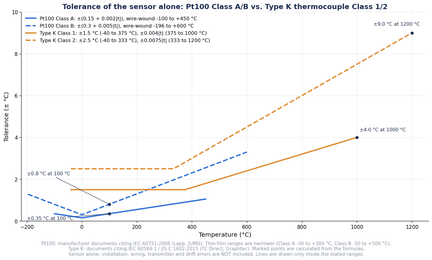
In the table, t is the temperature value in °C without regard to sign. Calculated from the formulas, K Class 1 is ±4.0°C at 1000°C (0.004 × 1000), and Class 2 is ±3.75°C at 500°C (0.0075 × 500) and ±9.0°C at 1200°C (0.0075 × 1200). At the Class 1 boundary of 375°C, 0.004 × 375 = 1.5°C, which joins the fixed value of ±1.5°C. Graphtec’s material states that “Class 1 is expensive. Class 2 is generally used.”
When choosing a type, also look at how it changes in service. Document DE18 from US maker Tempco describes drift tendencies by type: K is medium to high at high temperatures; N drifts less than K and is often chosen as a stable alternative to K; J suffers iron oxidation, rust and embrittlement; T has low drift at low temperatures but its copper oxidizes at high temperatures; and R and S are subject to contamination and grain growth.
For wiring, use extension/compensating cable matched to the thermocouple type. IEC 60584-3:2021 specifies the identification and manufacturing tolerances of extension and compensating cables for industrial processes and does not cover MI-type extension and compensating cables. Because temperature differences at junctions become errors, Graphtec recommends, strictly speaking, dedicated terminal blocks and connectors with the same thermoelectric characteristics.
Pt100 Class A vs Class B and Wiring Configurations
Pt100 tolerances are shown here as values from manufacturer material based on IEC 60751 (2008 edition). Cable and sensor maker Lapp publishes the following values as “the accuracy classes specified by IEC 60751:2008,” and JUMO’s explanation gives the same values for Class A and B. Note that the applicable temperature range differs between wire-wound and thin-film types.
| Class | Tolerance formula (°C) | 0°C | 100°C | Wire-wound range | Thin-film range |
|---|---|---|---|---|---|
| AA | ±(0.1 + 0.0017·t) | ±0.1°C | ±0.27°C | −50 to +250°C | 0 to +150°C |
| A | ±(0.15 + 0.002·t) | ±0.15°C | ±0.35°C | −100 to +450°C | −30 to +300°C |
| B | ±(0.3 + 0.005·t) | ±0.3°C | ±0.8°C | −196 to +600°C | −50 to +500°C |
| C | ±(0.6 + 0.01·t) | — | — | Not stated | Not stated |
t is the temperature value without regard to sign, and the 0°C and 100°C values are those published by Lapp. Calculated from the formulas, at 200°C Class A is ±0.55°C and Class B is ±1.3°C. The Endress+Hauser (E+H) TM311 technical information also gives a maximum error of 0.55°C for Pt100 Class A over −50 to +200°C, which is consistent with the formula. According to Lapp, Class C is not common in industrial measuring circuits. JUMO explains that Class B offers a good balance with price and is the most common in industry, while Class A is used for applications such as heat-transfer medium temperatures in the energy industry.
The figure below plots the tolerances of Pt100 Class A and B and thermocouple K Class 1 and 2, calculated from the formulas and drawn only within their applicable ranges. These are tolerances of the sensor alone and do not include errors from installation, wiring, transmitters or aging.
The edition of the standard also matters. The third edition of IEC 60751 was published on January 27, 2022, replacing the 2008 edition. Senmatic explains that since 2008 the whole thermometer, not just the element, must meet the class at its connection end, and that the same applies in the 2022 edition. The company points out that requests for quotation still reuse specifications from the first edition of 1983.
Wiring configurations are 2-wire, 3-wire and 4-wire. According to Senmatic, Classes A and AA require 3-wire or 4-wire connection under the standard. The company further states that with long 3-wire cabling, Class A cannot be verified because of lead resistance tolerances, and that to meet Class A or better under the 2008 edition you should order 4-wire (the company’s view). In this article, we take the view that if you specify Class A or better, the specification should decide between 3-wire and 4-wire together with the cable length.
“Class” Is Not the Error at the Measuring Point: Think in Terms of the Measurement Chain
This is the second pillar of this article. Class A or Class 1 is the tolerance of the element or wire, or of the thermometer alone. The error in the value read on site also includes the elements before and after it.
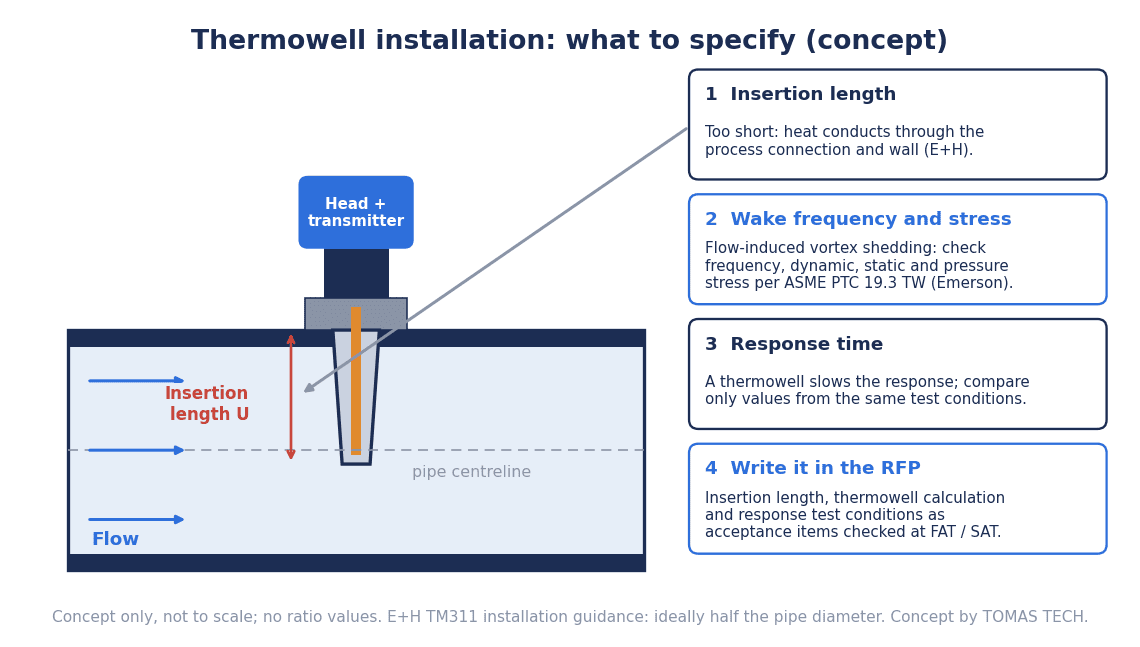
- Thermowell and insertion length: according to E+H’s TM311 installation instructions, if the insertion length is too short, heat conducted through the process connection and vessel wall causes errors.
- Response lag: placing the sensor in a thermowell slows its response. For E+H’s TM311, under the same test conditions (in water at 0.4 m/s, 10 K step), the t90 of the TipSens element is 1.5 seconds in direct contact and 3 seconds with a 6 mm thermowell (4.3 × 20 mm). According to Emerson, the T90 response of a conventional thermowell installation is generally in the range of 30 seconds to 3 minutes (the test conditions differ from E+H’s values, so the two cannot be compared).
- Changes in the element or wire: because a thermocouple’s EMF is generated not at the tip but in the section with a temperature gradient, the abstract of a paper from the UK’s National Physical Laboratory (NPL) states that thermoelectric inhomogeneity is one of the most important sources of uncertainty.
- Wiring: lead resistance for RTDs, and for thermocouples the compensating cable, temperature differences at junctions, and cold-junction compensation are sources of error.
- Transmitter: analog-to-digital conversion error is added. Yokogawa states a typical Pt100 A/D accuracy of 0.1°C for the YTA710, but this is the value for the transmitter’s A/D conversion section, not the accuracy including the sensor.
There are measures for the transmitter-side error. Yokogawa explains that each actual RTD deviates individually from the IEC 60751 standard curve (within its tolerance), and that the CM1 option lets you enter Callendar-van Dusen (CvD) coefficients to improve the accuracy of the transmitter-and-sensor system. E+H also explains that it offers “sensor-transmitter matching” as a separate service, in which the sensor is calibrated at at least three temperatures to determine its actual characteristic and the CvD coefficients are set in the transmitter.
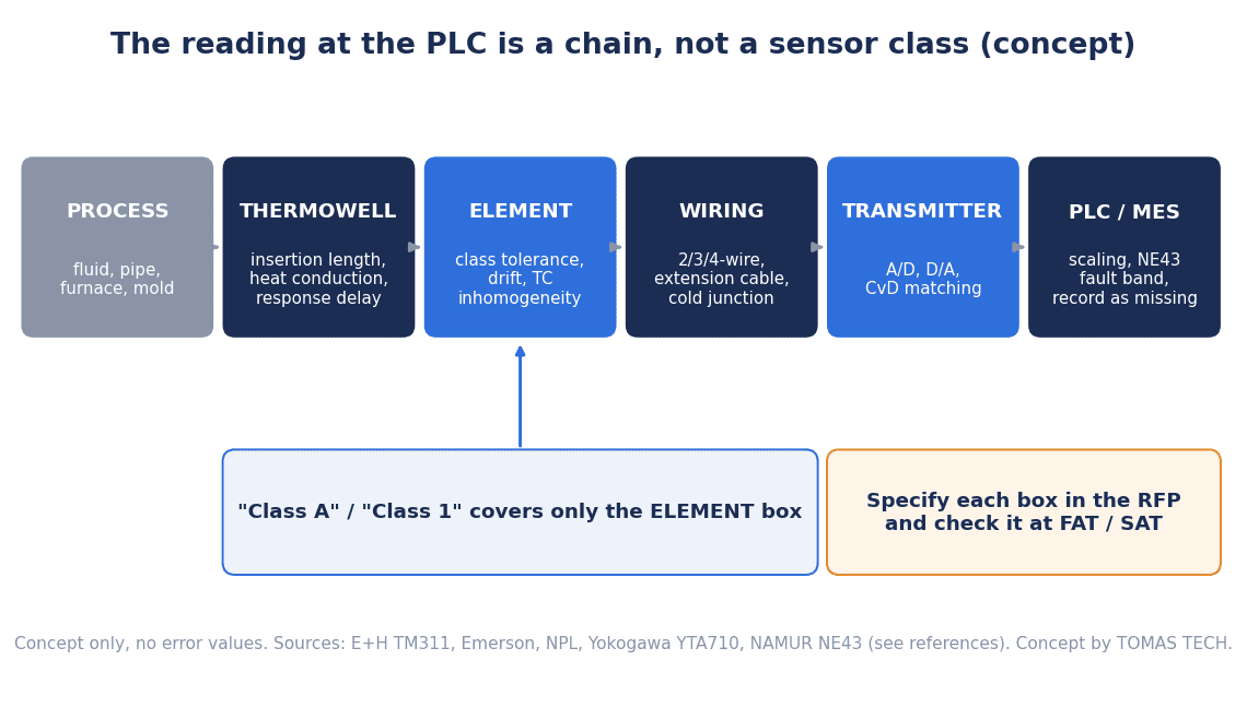
The MI thermocouple standard IEC 61515:2016 also states in its official abstract that “the specifications apply to new products as delivered and not to products after use.” That is why, in selection, we think it is necessary to define the required accuracy for each measuring point and to pin down, through the specification and acceptance tests, where in the measurement chain errors arise.
Thermowell Selection and Installation
A thermowell protects the sensor from the process, but because it protrudes into the flow, it can be damaged by vortex-induced vibration.
According to ASME’s page, ASME PTC 19.3 TW-2016 (reaffirmed in 2025, current) covers thermowells machined from bar stock, including those attached by flange welding, threading, or welding to vessels or piping. Thermowells made from pipe, special surfaces such as knurling or helical strakes, and welds on the shank or tip (including spray coating and overlay) are out of scope. Mounting methods and standard dimensions are also outside its scope.
Emerson’s white paper (March 2014) explains the assessment approach. According to the company, the thermowell fatigue failure at Monju in Japan was caused by in-line resonance, which the 1974 edition did not take into account. TW-2010 assesses against four criteria, the frequency limit, dynamic stress limit, static stress limit and hydrostatic pressure limit, and newly uses the Scruton number to represent damping. Corrosion and erosion of the material must be considered separately.
In this article, we think the practical approach is not to judge values such as the frequency ratio in-house, but to ask in the RFP for “a strength calculation in accordance with the current ASME PTC 19.3 TW” together with the flow velocity, pressure, temperature and fluid conditions it assumes.
On insertion length, E+H’s TM311 installation instructions state that in piping the insertion length should ideally be half the pipe diameter. Calibrator maker Fluke gives “20 times the probe diameter plus the length of the sensing element, or more” as a guideline for avoiding axial stem conduction error during calibration, with the example that a 3/16-inch diameter probe with a 3/4-inch sensing element needs a minimum of 4½ inches. Both are manufacturer installation instructions or rules of thumb, not values from a standard. The table of contents of IEC 60751:2022 includes a test item for “minimum immersion depth,” but we have not confirmed its values for this article.
As a method that does not use a thermowell, Emerson describes Rosemount X-well Technology, which calculates process temperature with a thermal conductivity algorithm from the ambient-side and pipe-surface temperatures. However, the company itself states that what affects accuracy most is the difference between process temperature and ambient temperature, and that it can be considered for control applications that are not highly critical. It is better not to assume that it always delivers the same accuracy as a thermowell replacement.
Drift and How to Think About Replacement
Thermocouples, base-metal thermocouples in particular, change characteristics in service. According to the abstract of the NPL paper, wire homogeneity can deteriorate rapidly in service, especially for base-metal thermocouples.
Tempco’s document DE18 describes type K as follows: an additional drift of about 1 to 2°C can begin in the 200 to 600°C range; it peaks around 400°C and can become permanent if cooled rapidly; holding at 500°C for 3 to 4 hours, cooling slowly and recalibrating can limit the effect, but this reverts if the thermocouple is exposed to temperatures above 600°C. Because the temperature bands differ between sources, we treat this as Tempco’s explanation.
In this article, we think the following three points are practical ways to prepare for drift.
- For thermocouples used at high temperatures, decide when to do periodic comparisons or replacement after recording the operating temperature and operating hours.
- Make it possible to compare important measuring points against another sensor. According to Yokogawa, the YTA710 has dual inputs and can switch to a backup on sensor failure and calculate the average and differential temperature.
- Because thermocouple wire homogeneity can deteriorate in service (NPL), have a spare-parts plan that assumes replacement.
Transmitters and Signals: 4-20 mA, NAMUR NE43, HART and IO-Link
When using a transmitter, you need to decide which part of the 4-20 mA signal counts as a “failure.” NAMUR NE43 is not a standard but a NAMUR recommendation, and it divides the 4-20 mA signal range into bands. As explained by ICS Schneider, a German instrument sales and calibration company, about 3.8 to 4.0 mA is the permitted lower range, 4.0 to 20.0 mA is the normal measuring range, and 20.0 to about 20.5 mA is the permitted upper range, while a downscale failure is normally about 3.6 mA or less and an upscale failure is normally about 21 mA or more.
| Signal range | Meaning (NE43 band) | Implementation examples |
|---|---|---|
| 3.6 mA or less | Failure (downscale) | E+H TM311 can be set to 3.6 mA or less. Pyromation T71 outputs 3.6 mA or less or 21.0 mA or more on open circuit (sensor break) or short circuit |
| 3.8 to 4.0 mA | Below the lower limit of the measuring range | Both products 4.0 → 3.8 mA |
| 4.0 to 20.0 mA | Normal measuring range | — |
| 20.0 to 20.5 mA | Above the upper limit of the measuring range | Both products 20.0 → 20.5 mA |
| 21.0 mA or more | Failure (upscale) | E+H TM311 high side can be set from 21.5 to 23 mA |
The actual failure current depends on the transmitter and its configuration. ICS Schneider gives 3.5 mA and 21.5 mA as examples, and explains that whether upscale or downscale is better cannot be decided in general terms but depends on the plant’s safe-side philosophy.
In addition to the analog value, some communication protocols can pass sensor status and diagnostics to higher-level systems. According to E+H, the TM311 automatically detects IO-Link or 4-20 mA, and in IO-Link mode sends all failure information digitally. The respective companies explain that JUMO’s dTRANS T09 supports 4-20 mA or IO-Link, and Yokogawa’s YTA710 supports 4-20 mA + HART 7, among others. Acceptance design for IO-Link is covered in “IO-Link Implementation: Sensor Data Integration and Acceptance,” and upgrading existing HART instruments in “Ethernet-APL Implementation.”
Collecting Data into PLC/MES and Handling Failures
If you keep temperature in your traceability records, it is important not to record failure signals as temperature values. ICS Schneider gives an example in which one wire of a Pt100 breaks and the PLC interprets it as the upper-range value of 200°C, explaining that if 21.5 mA is simply displayed as 200°C, the information “sensor failure” is lost. The company says it is useful to align the PLC-side thresholds with the transmitter settings and, to avoid false alarms from noise, to add a short hysteresis or a time-based plausibility check.
In this article, we take the view that the following three points should be decided between the PLC and MES.
- Record currents in the failure bands not as temperature values but as “missing data” with a status code.
- Keep the bands above the upper limit and below the lower limit of the measuring range as states separate from failure.
- Decide which of the diagnostic information available via HART or IO-Link to bring into the MES.
How to decide the number of tags and polling interval for PLC data collection is covered in “PLC Data Collection 2026,” and detection of missing data and acceptance criteria in “Factory Sensor Data Loss Prevention.” If you record furnace temperatures as heat treatment process records, also see “Heat Treatment Process Record Systems.” Note that we could not confirm any industry-standard values for storage granularity or retention period in the MES. You need to decide these in-house according to the application.
How Major Manufacturers Describe Their Products
The public information from major manufacturers is summarized below in alphabetical order, covering functions only. All of it is each company’s own description, and this article does not recommend any particular product. Because test conditions differ, we also do not rank the figures against one another.
| Manufacturer | Product | Company’s description (summary) |
|---|---|---|
| Emerson | Rosemount X-well Technology | Calculates process temperature from ambient-side and pipe-surface temperatures, measuring without a thermowell. Up to 650°C in combination with the 3144S transmitter. Can be considered for control applications that are not highly critical |
| Endress+Hauser | iTHERM CompactLine TM311 | Pt100 Class A, 4-wire, −50 to +200°C. Automatically detects IO-Link or 4-20 mA. In 4-20 mA mode, failure information in accordance with NE43 |
| Endress+Hauser | iTHERM TrustSens TM371 | Self-calibrating RTD for hygienic applications. Calibrates automatically at a reference point of 118°C or 39°C and automatically generates a traceable calibration certificate. 4-20 mA, HART |
| JUMO | dTRANS T09 | Pt100/Pt1000 (4-wire) input, 4-20 mA or IO-Link, M12 at both ends, IP66/IP67/IP69. For retrofitting existing equipment |
| Pyromation | T71 | Failure signal per NE43 (3.6 mA or less or 21.0 mA or more), lead resistance error detection per NE89 |
| Yokogawa | YTA710 | RTD, thermocouple, resistance and mV inputs, dual input. 4-20 mA + HART 7, BRAIN, FOUNDATION Fieldbus. CvD coefficients can be set with the CM1 option |
TrustSens self-calibration is a function for hygienic applications at a specific temperature point; it does not mean that calibration of furnace or mold temperature sensors becomes unnecessary. Likewise, the response time E+H gives for the TM311 (in water at 0.4 m/s per IEC 60751, 10 K step) and the “30 seconds to 3 minutes with a thermowell installation” Emerson gives were obtained under different conditions, so they cannot be compared.
Prices vary widely with type, class, thermowell (material and whether a strength calculation is included), transmitter (HART/IO-Link) and the scope of the calibration certificate. We could not confirm published prices on the official pages of the manufacturers above, so you will need to obtain quotations through the RFP.
Calibration and How to Decide the Calibration Interval
The third pillar is calibration. As E+H explains, thermometers can be calibrated either by using fixed points such as the 0°C ice point or by comparison with a precision reference thermometer, using a calibration bath with a uniform temperature distribution or a calibration furnace into which the unit under test and the reference thermometer can be inserted sufficiently. For field sensors, we think comparison calibration against a reference thermometer will be the main approach.
The calibration interval is not something a standard decides for you. ISO/IEC 17025:2017 sets out requirements for the competence, impartiality and consistent operation of testing and calibration laboratories. ILAC-G24:2022 / OIML D 10:2022, which gives guidance on determining recalibration intervals, states that “there is no single best practice universally applicable for establishing and adjusting recalibration intervals.” Initial intervals are determined mainly by risk assessment, and the factors to consider include the required uncertainty, the risk of exceeding the maximum permissible error, the manufacturer’s recommendation, wear and drift trends, the extent and severity of use, environmental conditions, the influence of the measurand (high temperature on thermocouples is given as an example), and the frequency and results of intermediate checks. ICS Schneider also explains that DIN EN 60584 does not specify a fixed calibration interval.
The same document calls for keeping calibration results as a history to serve as the basis for future interval decisions, and for performing intermediate checks between calibrations. It presents five review methods, and platinum resistance thermometers (combined with the calendar-time method) are given as an application example of in-use checks.
In this article, we think that recording the flow of setting the initial interval by risk and reviewing it with calibration history and intermediate checks is a practical way to explain the basis of the interval during an audit. Due-date management is covered in “Calibration Management System,” and checking the measuring points and uncertainty on certificates in “AI Verification of Calibration Certificates in Manufacturing.”
As for calibration infrastructure in Thailand, the national metrology institute NIMT has a temperature and photometry department. NIMT held a thermocouple calibration training course on May 28-30, 2025, whose content included demonstrations of cold-junction compensation, immersion effects and inhomogeneity effects, and uncertainty calculations. In addition, the Electrical and Electronics Institute (EEI), affiliated with Thailand’s Ministry of Industry, states on its own page that it has been accredited by the Thai Industrial Standards Institute (TISI) for calibration based on ISO/IEC 17025 since 2005 and has temperature and humidity calibration fields.
What to Write in the RFP
Here we turn the points so far into items for a temperature sensor RFP (request for proposal).
| Item | What to write in the RFP |
|---|---|
| Measuring target and temperature range | What is measured (piping, furnace, mold, tank), normal temperature and maximum/minimum temperatures, required response speed |
| Type and class | Thermocouple type and class, or Pt100 class. The standard and edition the tolerance is quoted from (e.g., whether IEC 60751 is the 2008 or 2022 edition) |
| Construction | Wire-wound or thin-film, sheath/MI construction, terminal head, number of elements (single or dual) |
| Thermowell and strength calculation | Material, process connection, strength calculation in accordance with the current ASME PTC 19.3 TW and its assumed conditions (flow velocity, pressure, temperature, fluid) |
| Insertion length | Basis for the insertion length (pipe diameter, installation instructions) and a drawing of the mounting position |
| Wiring | For RTDs, 3-wire or 4-wire; for thermocouples, the type of compensating cable and how junctions are handled |
| Transmitter and signal | 4-20 mA failure current (downscale or upscale, and the value), HART/IO-Link, diagnostics, whether CvD matching is required |
| Data integration | PLC tag names and scaling, settings that treat failure bands as missing data, diagnostic items to bring into the MES |
| Calibration | Issuer of the calibration certificate, whether ISO/IEC 17025 accredited, calibration points and uncertainty, traceability |
| Spares and replacement | Number of spare sensors, replacement procedure, recalibration on replacement |
| Documentation | Material corresponding to the “information to be provided by the supplier” specified in Clause 7 of IEC 60751:2022, operating manuals, drawings |
To avoid reusing specifications from an old edition, we think it is important for the RFP to state the edition and the wiring configuration together.
What to Confirm at FAT/SAT
In this article, we propose including the following items in FAT/SAT. Set the pass criteria in-house according to the required accuracy of each measuring point.
- Comparison calibration: place the sensor alongside a reference thermometer and compare values at multiple points across the operating temperature range. Also check that the measuring points on the calibration certificate cover the operating temperature range.
- Loop check: output a simulated signal from the transmitter and confirm that the PLC and MES display and record it as the same temperature.
- Signal on open circuit (sensor break) or short circuit: disconnect the sensor wiring and confirm that the configured failure current is output, and that the PLC and MES record it as missing data rather than as a temperature, distinguished from the above-upper-limit and below-lower-limit bands.
- Tag names and scaling: confirm that measuring point numbers, tag names and ranges match the drawings.
- Installation condition: at SAT, confirm the insertion length, thermowell mounting and the condition of compensating cable junctions visually and in records.
Frequently Asked Questions
Should I choose a thermocouple or an RTD?
If the temperature you measure falls within the RTD range (normally −50 to 600°C according to Senmatic) and accuracy and stability matter most, a Pt100 is the candidate; for high temperatures such as furnaces, a thermocouple is the candidate. In either case, consider accuracy across the whole measurement chain.
What is the difference between Pt100 Class A and Class B?
According to manufacturer material based on IEC 60751 (2008 edition), Class A is ±(0.15 + 0.002·t) and Class B is ±(0.3 + 0.005·t), giving ±0.35°C and ±0.8°C respectively at 100°C. The applicable range differs by construction: Class A is −100 to +450°C for wire-wound and −30 to +300°C for thin-film. According to Senmatic, Classes A and AA require 3-wire or 4-wire connection under the standard.
Is a thermowell always necessary?
If you use a thermowell, it can be damaged by flow-induced vibration, so request a strength calculation in accordance with the current ASME PTC 19.3 TW. Methods without a thermowell also exist, but Emerson itself positions its method as one that can be considered for control applications that are not highly critical.
How should the temperature sensor calibration interval be decided?
No interval is set by a standard. ILAC-G24 / OIML D 10:2022 states that there is no universally best method, and describes setting the initial interval by risk assessment and reviewing it with calibration history and intermediate checks.
What does the PLC see when a sensor breaks?
When a transmitter is used and configured per NE43, the failure current is about 3.6 mA or less for downscale and about 21 mA or more for upscale. If the failure current is converted directly into temperature, it may be recorded as the upper- or lower-range temperature, so configure failure bands to be treated as missing data, and confirm this at FAT/SAT by disconnecting the wiring.
Summary
- We take the view that what you decide first in industrial temperature sensor selection is not the catalog class but three things: (1) what temperature you need to know, over what range and how fast; (2) the error across the whole measurement chain; and (3) writing the thermowell strength calculation, failure signal, diagnostics and calibration interval into the RFP and confirming them at FAT/SAT.
- Thermocouple tolerances are values from sources citing IEC 60584-1 / JIS C 1602:2015 and are tolerances of the thermocouple wire. Pt100 tolerances are values from manufacturer material based on IEC 60751 (2008 edition), and the applicable range differs between wire-wound and thin-film types.
- Errors from the thermowell, insertion length, wiring, transmitter and drift over time stack up in the error at the measuring point.
- The 4-20 mA failure bands (3.6 mA or less and 21.0 mA or more under NE43) are not recorded as temperatures but treated as missing data.
- The calibration interval is not decided by a standard; decide and record it based on risk assessment, calibration history and intermediate checks.
Even at the stage of taking inventory of existing temperature measuring points or considering which measuring points to bring into your MES, you are welcome to consult TOMAS TECH. Please contact us here.
References
- IEC, “IEC 60584-1:2013 Thermocouples – Part 1: EMF specifications and tolerances” https://webstore.iec.ch/en/publication/2521
- IEC, “IEC 60584-3:2021 Thermocouples – Part 3: Extension and compensating cables” https://webstore.iec.ch/en/publication/63754
- IEC, “IEC 60751:2022 Industrial platinum resistance thermometers and platinum temperature sensors” https://webstore.iec.ch/en/publication/63753
- VDE VERLAG, “IEC 60751:2022 preview PDF” https://www.vde-verlag.de/iec-normen/preview-pdf/info_iec60751%7Bed3.0%7Db.pdf
- IEC, “IEC 61515:2016 Mineral insulated metal-sheathed thermocouple cables and thermocouples” https://webstore.iec.ch/en/publication/24665
- ASME, “PTC 19.3 TW – Thermowells” https://www.asme.org/codes-standards/find-codes-standards/thermowells
- Emerson, “White Paper: Thermowell Calculations,” March 2014 (PDF) https://www.emerson.com/documents/automation/white-paper-thermowell-calculations-rosemount-en-89838.pdf
- TC Direct, “How accurate is a thermocouple?” https://tcdirect.co.uk/thermocouple-sensors/thermocouple-accuracies.aspx
- Graphtec, “Guide to Selecting Thermocouples: Basic Knowledge Vol.1” (PDF, Japanese) https://graphtec.co.jp/wp-content/uploads/Guidethermocouple_vol1.pdf
- ICS Schneider Messtechnik, “Temperature Measurement According to DIN EN 60584” https://www.ics-schneider.de/temperature-measurement-according-to-din-en-60584-what-needs-to-be-considered/?lang=en
- JUMO, “RTD accuracy class – PT100 according to IEC60751” https://www.jumo.group/us/en/about-us/blog/pt100-accuracy-class
- Lapp, “What are the Pt100 accuracy classes?” https://fi.lappgroup.com/products/temperature-measurement-and-instrumentation/faq/what-are-the-pt100-accuracy-classes.html
- Senmatic, “IEC 60751:2022 – the main points and updated tolerance classes” https://www.senmatic.com/sensors/knowledge/iec-60751-sensor-tolerance-classes
- Endress+Hauser, “Technical Information iTHERM CompactLine TM311” TI01439T/02.2020 (PDF) https://portal.endress.com/wa001/dla/5001120/9062/000/01/TI01439TEN_0220.pdf
- Endress+Hauser, “iTHERM TrustSens TM371” https://www.ca.endress.com/en/field-instruments-overview/temperature-measurement-thermometers-transmitters/iTHERM-TrustSens-TM371
- Pyromation, “T71 Programmable Temperature Transmitter” (PDF) https://pyromation.com/Catalog/tt07.pdf
- ICS Schneider Messtechnik, “Temperature Transmitter with Sensor Break: Correctly Configuring NAMUR Fault Signal” https://www.ics-schneider.de/temperaturmessumformer-bei-fuehlerbruch-namur-fehlersignal-upscale-und-downscale-richtig-parametrieren/?lang=en
- Yokogawa, “YTA710 Temperature Transmitter” https://www.yokogawa.com/solutions/products-and-services/measurement/field-instruments-products/temperature-transmitters/field-mount/yta710-temperature-transmitter/
- Emerson, “Rosemount X-well Technology” https://www.emerson.com/en/measurement-instrumentation/products/rosemount-x-well-technology-family
- JUMO, “dTRANS T09 Cable transmitter for temperature” https://www.jumo.group/nl/en/products/productdetails/707090
- Tempco, “DE18 Understanding True Thermocouple Accuracy” (PDF) https://www.tempco.com/wp-content/uploads/2026/07/DE18.ThermocoupleAccuracy.pdf
- Machin, Tucker, Pearce, “A comprehensive survey of thermoelectric homogeneity of commonly used thermocouple types,” 2018 (NPL) https://eprintspublications.npl.co.uk/7940/
- Fluke Calibration, “Stem Conduction Error” KA-03389 https://my.fluke.com/en-us/article/KA-03389
- ISO, “ISO/IEC 17025:2017” https://www.iso.org/standard/66912.html
- OIML, “ILAC-G24:2022 / OIML D 10:2022 Guidelines for the determination of recalibration intervals of measuring equipment” (PDF) https://www.oiml.org/en/files/pdf_d/d010-e22.pdf
- NIMT, “Calibration of thermocouples and thermocouple indicators,” May 2025 (PDF) https://training.nimt.or.th/OnlineRegister/TrainingProfile/20250113-NIMT-11020-12312,12321.pdf
- NIMT, “Hybrid Learning on Calibration of thermocouples and thermocouple indicators,” June 8, 2022 https://en.nimt.or.th/?p=6919
- Electrical and Electronics Institute, “Measuring Instrument Calibration Services” https://www.thaieei.com/en/services/measuring-instrument-calibration-services/
- The Star (Reuters), “Thai August factory output rises 4.44% y/y, beats forecast,” September 30, 2026 https://www.thestar.com.my/business/business-news/2026/09/30/thai-august-factory-output-rises-444-yy-beats-forecast
- Trading Economics, “Thailand Industrial Output Growth Beats Forecasts,” September 30, 2026 https://tradingeconomics.com/thailand/industrial-production/news/587981
- Trading Economics, “Thailand Business Confidence Remains Subdued,” October 2, 2026 https://tradingeconomics.com/thailand/business-confidence/news/589079


