



A pressure-sensitive safety mat is easy to price by its outside dimensions. It is much harder to prove that a person approaching a hazardous machine will step on its effective sensing area early enough for the machine to reach a safe state. The outside edge, effective sensing area, perimeter trim and joining trim are different things. A joint between two mats can require a specified active component; a floor ramp needs space; and the machine may coast after the controller reacts. These details determine the actual protection, project cost and factory acceptance test.
This guide is for engineering, EHS, maintenance, production and procurement teams adding mats to an existing machine or specifying a new cell in Thailand. It concentrates on floor layout, installation, the complete safety function and FAT/SAT evidence. It does not determine the legal requirements or compliance of a particular machine. Confirm the applicable Thai requirements, customer contract, destination-market requirements, machine-specific standards and editions with qualified project personnel.
Start with the hazard and the way people enter
Under ISO 12100:2010, risk assessment starts with hazards, tasks and foreseeable use. Ask which moving part, crushing point or stored energy must be controlled; from where a person can approach; and what the machine must do when the mat is actuated. Observe normal production, changeover, cleaning, jam removal, troubleshooting and maintenance separately. Mark the actual paths taken while carrying tools or workpieces, not only the ideal path in a layout drawing. An opening beside a tool rack or a temporary pallet can change how an operator reaches the machine.
A mat detects pressure applied to a specified part of the floor. It does not by itself prevent a person from stepping around it, reaching over it, entering from a side opening or remaining in the hazard zone after leaving it. Fixed guarding, interlocked access, a light curtain and the mat can form complementary measures. If the mat is intended to be the only approach path, the physical layout must prevent bypassing that path. If a trolley regularly occupies the mat, repeated nuisance stops can encourage unsafe workarounds; assess the material route during design.
ISO 13856-1:2013 sets general design and test principles for pressure-sensitive mats and floors actuated by feet. Its official scope expressly does not set the effective sensing-area dimensions for every application, decide whether a mat is suitable for every situation or assign the required performance level to a particular machine. Purchasing a mat described as compliant with that standard therefore does not validate its position, the stop or the reset logic. Write the safety function at machine level: for example, actuation of the defined floor zone shall cause the specified hazardous motion to stop, prevent restart while occupied and require the specified conditions before restarting.
Record site conditions before requesting quotes
The site survey should identify the hazard, openings, operator positions, regular aisles, trolley and forklift routes, columns, floor levels, drainage and washing area. Capture the existing controller, drive or valve, stopping element and sources of stored energy. Make production, maintenance and EHS agree on the tasks that require access. Specify what safe state means for each motion: a normal PLC run bit changing to OFF is not necessarily proof that the hazardous movement has ceased. Record whether pneumatic, hydraulic or gravity energy can cause further movement after the control output changes.
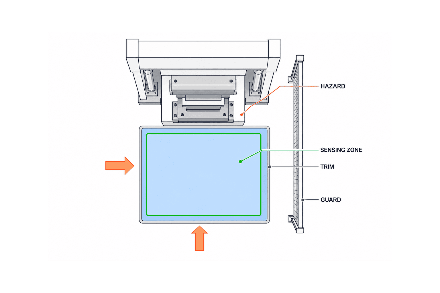
Draw the outside envelope and the effective sensing zone separately
Do not order a 1,000 × 1,500 mm mat merely because a floor opening has those dimensions. On the installation drawing show the mat outline, effective sensing area, perimeter trim, active joining trim, cable exit, mounting points and any ramp or recess as separate layers. Manufacturer drawings distinguish these dimensions in different ways. Rockwell Automation’s March 2026 MatGuard technical data, for example, illustrates how perimeter and active joining trim alter the total footprint. Its dimensions are product-specific and should not be copied onto another manufacturer’s design.
Draw several human approach lines from the real work area to the hazard. Each path that the risk assessment relies upon must cross an adequate detection zone before the person can reach danger. Test the side path next to a fixture, the narrow route between a rack and a guard, and the path used during cleaning. The nominal width of an opening is not enough if a person can stand beside the mat and reach the hazard. Also identify locations where a pallet, cart or discarded material can cover or move the mat.
Check the manufacturer’s specified active area and operating conditions at the edges and joints. A mat is not guaranteed to detect every light object or every toe position. ISO 13856-1 describes a defined scope of persons it is designed to detect; the project’s population and operating conditions still need review. Prepare a commissioning test map with representative centre, edge and joint points, and with actual footwear and work postures where relevant. Use the product’s test procedure and approved test pieces or methods, rather than inventing a universal actuation force.
Use measured stopping time to size and position the zone
ISO 13855:2024 addresses positioning and dimensioning safeguards, including detection zones for pressure-sensitive mats and floors, in relation to human approach. Use the edition selected for the project, the actual approach geometry and measured stopping performance. An old formula copied from a catalog is not a substitute for a machine-specific calculation. Some 2026 manufacturer literature still refers to an earlier edition in its example. Record the edition and rationale in the design review.
This separation-distance discussion applies when the mat safeguards a person approaching the hazard. ISO 13855:2024 excludes safeguards used solely for presence sensing from its separation-distance provisions; assess that occupancy-only function on its own terms. If the same mat serves both purposes, specify and validate each function separately.
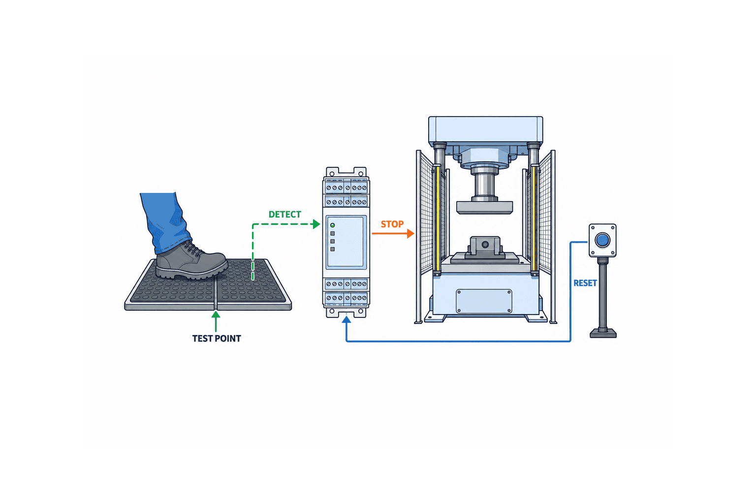
The time from stepping on a mat to absence of hazardous motion includes the mat response, monitoring unit, safety relay or safety PLC, output device, drive or valve and machine coast-down. Measure or assess the full chain under appropriate operating conditions. Tool mass, load, speed, brake wear and air pressure may affect the stop. Document the measuring instrument, conditions, number of trials, recorded values and value used for the safeguard-position calculation. A fast sensor response alone says little about overall stopping time.
If the available floor depth cannot provide an adequate position, a larger purchased mat may not resolve the problem. Consider modifying physical access, improving stopping performance or selecting complementary protection. Compare those options against material movement, cleaning and maintenance access. The people who will use the machine should walk through a proposed full-size floor layout before the position is frozen.
Define stop, occupancy and restart as different behaviours
Stopping on actuation is only one part of the function. State what happens while a person stands on the mat, after they step off it, during a fault, after power returns and after reset. Automatic reset availability on a product is not a reason to select it. If a person can step off the mat into the hazard space, loss of the occupancy signal must not allow an unexpected restart. Evaluate reset location, visibility of the protected zone and additional measures. ISO 14118:2017 addresses the prevention of unexpected start-up, while the specific solution is decided from the machine risk assessment.
Design every joint, perimeter and ramp
For multiple mats, ask whether the joint is part of the effective sensing zone. Rockwell’s MatGuard documents describe active joining trim intended to detect a person on the junction when correctly installed. That result depends on the specific mat and trim system; two mats pushed together under ordinary metal edging do not necessarily provide an active joint. Require a dimensioned plan naming mat and trim models, joining method, fixings, clearances and joint test points. Identify irregular shapes and how they will be made. Do not cut or drill a mat on site unless the manufacturer explicitly allows it.
Perimeter trim retains the mats and can help manage trip risk or cable routing, but the trim footprint is not automatically active sensing area. A standard, cable-channel or ramp profile may be needed depending on trolley wheels, foot traffic and the floor. Check wheel load, turning, washdown, swarf, oil, chemicals, temperature and cleaning equipment against the selected product’s actual ratings and instructions. “Industrial grade” is too broad to be a procurement criterion. Assess how the floor will be cleaned and whether oil or debris can collect below trim.
A recessed installation needs recess dimensions, tolerances, drainage, fixing and replacement access. A surface installation needs an appropriate ramp, edge fixing and assessment of trolley crossing. A warped floor may lift the mat or undermine the installation. Include floor preparation, anchor positions, approved adhesives and reinstatement in the construction scope. Plan cable exits away from wheel tracks and show mechanical protection, bend radius and accessible connection points. A joint buried in the floor can turn a minor cable failure into a long shutdown.

Assess the complete electrical safety function
Connect the mat through a compatible monitoring device or safety control architecture that performs the specified safety function. Feeding its state to an ordinary PLC merely to show an alarm does not validate a protective stop. The circuit drawing should show the mat wiring, open- and short-circuit monitoring, number of mats, channel arrangement, reset, safety outputs or safety communication, and final contactor, drive or valve. Rockwell describes a four-wire system for fault detection in a specific MatGuard controller. Verify the selected combination’s wiring and limits against its own current instructions.
Determine the required control performance from the risk assessment. ISO 13849-1:2023 provides a method for designing and integrating safety-related control parts; ISO 13849-2:2012 describes validation through analysis and test of the specified safety functions, category and achieved performance level. A component label alone does not establish the achieved performance level of the installed machine. Preserve the relevant component reliability data and versions, wiring diagrams, software version, parameter backup and validation record. Evaluate sensor, logic, output, diagnostics and final stopping element together.
Do not assume that electrically connecting many mats is permissible. The permitted area, cable length, termination, connection order and compatible controller depend on the manufacturer. Rockwell says its particular MatGuard control unit can monitor multiple mats over a protected zone up to 100 m²; this is a product-specific capability, not a universal mat limit. The proposal should show that the actual combination remains within its manufacturer’s specified conditions. Define a replacement procedure and retest scope before the first mat fails.
Compare mats with other safeguards without losing the floor problem
A safety mat can be useful where floor occupancy itself needs detection. A light curtain detects passage through a defined plane, but does not automatically resolve the question of a person remaining inside. A door switch monitors a guard door, but does not detect a person standing in an open-front work area. Conversely, a mat does not prevent reach-over or side access. Choose a combination from the hazard, access routes and machine stop, rather than treating product categories as interchangeable. For related components, see our guides to safety relay selection and safety door switch selection.
Make the RFP compare a finished function, not only mat prices
Separate the bill of materials into mat size and quantity, active joining trim, perimeter and ramps, cables and protection, monitoring unit, safety-control modification, final stopping-element modification, floor work, drawings, testing, training and spares. Two quotations can have the same mat count and very different installed scope. Ask vendors to provide both the material price and the cost of a validated function, with exclusions visible. Define who measures stopping time, who approves the floor design, who updates the risk assessment and who signs the acceptance record.
| Item | Evidence requested in the RFP | What acceptance must demonstrate |
|---|---|---|
| Hazard and approach | Risk assessment and actual path drawing | Bypass, side entry and reach paths reviewed |
| Detection zone | Separate outline and active-zone drawing | Centre, edge and joint test points work |
| Stopping performance | Test plan and selected standard edition | Machine measurement and position reassessment |
| Electrical system | Circuit, diagnostics and reset specification | Fault, restart and final stop behaviour |
| Floor installation | Trim, ramp, drainage and cable drawings | Fixing, trip risk, cleaning and trolley passage |
| Maintenance | Inspection, replacement and spare list | Retest and records after replacement |
Avoid unsupported claims such as a universal safe distance, universal IP rating or a legal obligation inferred solely from the use of an ISO standard. Equipment type, location, destination market and customer contract can change the relevant requirements. Request model-specific documents, edition and operating conditions for every numeric value in the specification.
Split FAT from SAT and retain the evidence
FAT is a pre-shipment opportunity to check the delivered models, drawings, safety logic, controller settings, reset and feasible simulated faults. It cannot necessarily test the installed floor, actual approach paths or final machine stopping time. Record tests deferred to SAT and freeze software, parameters and circuit versions. A successful FAT does not certify the final mat position.
At SAT, test installed mats at representative centre, edge and joint points and along every approach route relied on by the design. Measure the stop and check the calculated position with the completed equipment. Test simultaneous actuation, prevention of restart while occupied, reset after release, power loss and return, open and short faults, diagnostic behaviour and interactions with upstream equipment. Use controlled fault injection under an approved safe method. Test the final floor condition after temporary installation cables have been removed.
Production and maintenance should inspect fixed edges, trip points, trolley wheel contact, drainage and cleanability. Record the test point, expected outcome, observed result, evidence, correction and approval. Define who may authorize production start and require open safety issues to be resolved first. Validation under ISO 13849-2 is more than a checklist of individual devices: it connects the specified safety function with analysis and testing of the installed system.
Plan inspection and change control from day one
Routine checks can include surface damage, slipperiness, trapped debris, loose trim, damaged cable, fault indication, actuation, stop and reset. Set the frequency from the manual, risk assessment, contamination and duty rather than choosing a universal interval. Periodic checks should revisit edge and joint actuation, fault detection, stopping performance and floor wear. Keep records of tester, points, result, action and authorization to restart. If a circuit was temporarily bypassed for maintenance, restoration and independent retest must be explicit steps.
Changes to speed, brake, control software, floor layout, mat model, material route or access opening can invalidate the original protection assessment. Even a replacement with the same outside dimensions may have a different effective sensing area or connection method. Treat substitutions through change control, review affected safety functions and repeat the relevant tests. If nuisance stops occur, investigate the workflow and floor layout. Do not respond by shorting or disabling the mat.
Resolve three boundaries before installation
The first boundary is between the safety function and ordinary information systems. Showing mat status on an HMI, counting stops or notifying maintenance can be useful, but decide separately whether any of those functions belong to the safety path. Check by drawing and test that the specified protective stop still works when the HMI restarts, communications fail or a production system misses an event. The screen can explain which mat operated, whether the condition is a fault or normal pressure and where reset is permitted. An added screen-based override or release action requires its own assessment.
The second boundary is between the protected floor and the real work area. A material box, hand tool or workpiece placed on the mat may hold the signal on, while operators may start walking around that object at the edge. Routes used only during changeover and cleaning often do not appear in the production layout. Tape the proposed full-size footprint onto the floor and have operators perform complete tasks. This simple review reveals problems that dimension checks alone miss. Put every resulting route or guard change back into the controlled drawing and assess the final arrangement.
The third boundary is between suppliers. A mat manufacturer may certify a component, a panel builder wire it, a floor contractor install it and a machine builder measure stopping time. Without a responsibility matrix, a defect at the cable outlet or active joint can fall between them. For the risk assessment, zone drawing, wiring, floor installation, stop measurement, FAT, SAT, corrections and training, name the author, reviewer and final approver. Mark interfaces with drawing numbers and physical inspection points. Agree before ordering who validates the finished machine-level safety function.
Handover documents and operator training
Retain the approved risk assessment and safety-function specification, standard editions, mat and trim models, layout and active-zone drawing, raw stop-time measurements and calculation, circuit drawing, software and parameter backups, FAT/SAT results and corrective-action log. Number the test points on the drawing so a later replacement can trigger the right retests. Give the plant more than a blank inspection form: it needs the action on a fault display, who to call, how to verify a replacement and who may authorize restart.
At a Thai plant, Japanese-only engineering documents will not reliably support daily checks by local operators and maintenance personnel. Prepare the necessary operation, inspection and warning instructions in the languages actually understood by the people using them. Train with the physical machine. Include not just a normal stop but a fault indication, torn mat, trolley snag, residual wash water and improper reset. Record who practised which action and any unresolved questions. Update this training when personnel or the floor layout changes.
Common questions
Does a safety mat make a light curtain unnecessary?
There is no general answer. A mat detects occupancy of a floor zone; a light curtain detects passage through a plane. If a hand or body can reach the hazard without stepping on the mat, more protection is needed. Decide from the risk assessment, actual approach and stop performance.
Is every joint between mats active?
No. It depends on the mat system and specified joining hardware. An active joining trim is designed for this purpose in some systems. An arbitrary edge strip is not equivalent. Verify the drawing and test the installed joint at SAT.
Does a “PL d” mat make the entire machine PL d?
No. The complete safety function includes input, logic, output, wiring, diagnostics and stopping element. Determine PLr from the risk assessment, calculate or assess achieved PL for the architecture and validate the installed function.
Which laws and standards apply to a Thai factory?
That depends on the machine, installation, destination market, customer contract and modification scope. The ISO documents cited here are design references, not a certificate of Thai legal compliance for a specific installation. Confirm applicability and editions with the local EHS and legal teams, machine builder and competent specialists.
Can another brand replace an existing mat of the same size?
Only after compatibility and change assessment. Active area, actuation, response, wiring, controller compatibility and trim interface may differ. Retest the stop and restart function after an approved substitution.
Conclusion
Select a safety mat by working backward from the hazard and real approach route. Draw the effective sensing area separately from the purchased footprint; measure the full machine stopping time; engineer every joint, perimeter, ramp and cable route; then validate the complete safety function in FAT and SAT. The product standard, positioning standard and control-system standards support that process, but none removes the need for machine-specific evidence.
If your Thai plant is considering mats on an existing machine or a new line, TOMAS TECH can help structure the site survey, RFP, stop-time test plan, control interface and FAT/SAT acceptance points while options are still open. Contact us to discuss the scope.
Primary references
- ISO 12100:2010 — Risk assessment and risk reduction
- ISO 13856-1:2013 — Pressure-sensitive mats and floors, confirmed in 2024
- ISO 13855:2024 — Positioning of safeguards
- ISO 13849-1:2023 — Safety-related parts of control systems
- ISO 13849-2:2012 — Validation
- ISO 14118:2017 — Prevention of unexpected start-up
- Rockwell Automation, Safety Mats and Edges Specifications Technical Data, March 2026
- Rockwell Automation, MatGuard Mat Manager User Manual, December 2024
- Rockwell Automation, MatGuard Control Unit User Manual, January 2024
- Rockwell Automation, Mat Controllers
Check editions, availability and application-specific requirements again before procurement.


