



Introduction: Three Things to Decide Before Implementing Laser Welding Monitoring
If your factory is considering laser welding monitoring, you may recognize some of these problems. The welds look clean, yet some of them lack sufficient penetration. The gap between the upper and lower sheets is too large, so some welds look joined but are not actually bonded. Sampling-based cross-section checks and tensile tests cannot cover every part. And customers are asking you to keep a quality record for each weld, at the level of the individual part.
In this article, we take the view that what you should decide first when implementing laser welding monitoring is not the type of sensor but the following three things.
- Which defects you want to find: build a table that maps defects to causes, because each method looks at something different
- How to build the good-weld reference and tolerance range, and how to maintain it: including what to do when the material lot or conditions change
- How to link the signal and judgment of each weld to the part ID (serial number), where to store them, and how to pass them to MES and quality records
The photodiode method is a correlation-based judgment that compares the light emitted by the process with reference data. The OCT method measures depth using a dedicated measurement beam. OCT, however, also comes with conditions, such as positioning of the measurement spot, the measurement range, and underestimation in unstable welds. With either method, no judgment is possible unless the good-weld reference is decided first.
In addition, welding standards such as ISO 13919 define quality levels for welded joints, welding procedures, equipment and safety. In the official abstracts we checked, we found no acceptance criteria for in-process monitoring. That is why, in this article, we take the view that the acceptance criteria for monitoring need to be agreed with the customer and verified at FAT and SAT.
A note before we start. This article is not a product recommendation or ranking. Product functions are presented as each company describes them in its public materials. The cost and benefit estimate uses hypothetical figures prepared for this article. Standards are covered only to the extent that we could confirm them in the official abstracts, and we do not deal with numerical tolerances in the body of the standards. Monitoring of resistance welding (spot welding) is covered in our article on resistance welding monitoring, and this article focuses on laser welding.
Why Laser Weld Quality Monitoring Is Under Scrutiny in Thai Factories Now
Around automobiles and batteries in Thailand, the production mix is shifting. We check the figures together with their scope and timing.
According to Placera (September 28, 2026), which carried a news agency report, the Federation of Thai Industries (FTI) announced that Thai vehicle production in August 2026 was 124,646 units, up 10.93% year on year. In the same month, domestic sales were up 25.6% year on year and exports were down 2.0% year on year. According to NST (August 25, 2026), production in July was 117,383 units, up 6.12% year on year. Meanwhile, the FTI has revised down its production outlook for 2026. The monthly increases and the full-year outlook do not point in the same direction.
Investment in electrification is also continuing. According to The Nation (July 3, 2026), as of May 2026 the Thailand Board of Investment (BOI) had approved 198 EV-related investment promotion projects worth more than 137 billion baht. Of these, batteries and ESS (stationary energy storage) accounted for 57 projects worth 33.5 billion baht. These are approval-based figures, not amounts actually invested. The article also does not say how many of the 57 projects are cell manufacturing, modules, packs or ESS.
As for individual cases, Just Auto (March 13, 2025) reported that an investment of about USD 1 billion in EV and ESS battery cell manufacturing by Sunwoda Automotive Energy Technology (Thailand) was approved by a Thai government committee. The first plant is in Chonburi province, and more than 1,000 jobs are expected. This, too, was reported at the time of approval, and no start of operation date is given. Also, according to Just Auto (March 1, 2024), Svolt set up a battery module and pack assembly plant in Chonburi through a joint venture with Banpu Next and started mass production. This is module and pack assembly, not cell manufacturing.
These are national and company-level figures and do not apply directly to the reader’s factory. Still, battery modules and packs, electric motors and body parts are areas where laser welding of busbars, tabs, hairpins and similar parts tends to increase. We expect that there will also be more cases where customer audits and quality requirements extend to a record for every single weld.
What Laser Welding Monitoring Is: Pre, In and Post
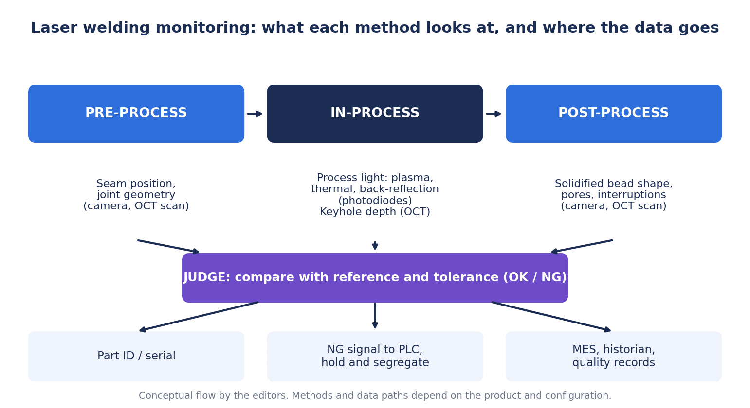
Laser welding monitoring is easier to organize if you divide it into three stages along the timeline.
| Stage | What is observed | Examples from public materials |
|---|---|---|
| Pre (before welding) | Joint geometry, the actual seam position, manufacturing deviations of the parts | Blackbird (iQLASE) explains that the OCT measurement beam runs ahead of the laser and analyzes the geometry and actual position of edges, fillets and overlaps |
| In (during welding) | Light, temperature, keyhole depth and so on during welding | Blackbird explains that the measurement beam enters the keyhole and measures penetration depth and other values. The photodiode method also belongs to this stage |
| Post (after welding) | Bead geometry, reinforcement, pores, interruptions in the bead | Blackbird explains that bead geometry and other features are analyzed after welding. Visual inspection with cameras also belongs to this stage |
In an article on bbr (March 4, 2026), Blackbird explains the idea of handling all three stages with a single OCT system, as shown above. IPG Photonics also explains that its LDD directly measures not only weld depth but also seam position, the cross-sectional profile and the surface of the finished bead.
On the research side, Baader et al. (EDPC 2021, FAU) state that OCT is promising for pre-, in- and post-process monitoring in hairpin welding. At the same time, they write that hairpins require complex beam paths and high focus speeds, which pose major challenges for existing OCT.
The focus of this article is in-process monitoring (during welding). Visual inspection that judges the bead from images after welding is covered in detail in our article on AI visual inspection of weld beads. Visual inspection is strong at defects that appear on the surface, while lack of bonding between sheets and penetration depth are hard to see from the surface. This is the main reason to consider in-process monitoring.
What the Photodiode Method Looks At
The photodiode method receives the light emitted by the process during welding and looks at changes in its intensity.
Chianese et al. (2022, ASME Journal of Manufacturing Science and Engineering) explain that passive sensors such as photodiodes gather indirect signals, and that those signals are correlated with weld features using statistical and machine learning techniques. According to the paper, photodiodes are inexpensive and simple in construction. They obtain information from the following three kinds of light.
| Signal | What light it is | Typical band given in the paper (for a near-infrared processing laser) |
|---|---|---|
| Plasma light | Emission from the metal vapor and plasma plume | 300–700 nm |
| Reflected light | Reflection of the processing laser | 1020–1090 nm |
| Thermal radiation | The thermal state of the processing zone (sees the temperature of both the melt pool and the plume) | 1200–2000 nm |
These bands are cited in the paper from another source.
The paper is a study aimed at battery tabs. The setup was remote laser welding of a lap joint of 300 µm Ni-plated copper and 300 µm Ni-plated steel. Under the conditions of this paper, variation in the gap between the parts could be diagnosed from step changes in the plasma light (and temperature) signals. The authors report that when the gap exceeded 100 µm, the result changed in a step from a sound weld to lack of bonding or no connection. The contribution of reflected light to gap detection was weak. They also write that the correlation between the plasma light and temperature signals exceeded 94%, and that as penetration became deeper, both the intensity and the scatter of both signals increased greatly.
However, this value of 100 µm is a result for this material, sheet thickness and set of conditions. It is not a value that can be used as a general allowable gap. The paper itself also states that there are overlapping regions in the feature space, so false negatives (missing a defect) and false positives (judging a good part as defective) can occur. Note that the authors include Precitec employees, and Precitec is one of the funders.
On the product side, Precitec explains that its Laser Welding Monitor (LWM) compares the characteristic process “fingerprint” of each weld with predefined reference data in real time, detects deviations and records process data for each weld. 4D Photonics also explains that its system evaluates signals with warning thresholds adapted to each application.
There are also statements from the opposite standpoint. In a Laser Focus World article (2015), developers at Laser Depth Dynamics, which developed inline interferometric measurement of the OCT type, write that photodiode systems do not directly measure penetration depth and need to be trained for each specific machine by comparison with destructive testing. This was written by a party developing a competing method and is not necessarily a neutral assessment. Still, in this article we take the view that the point that “building a reference requires matching against destructive testing” is worth keeping in mind whichever method you choose.
What the OCT Method Looks At
The OCT (optical coherence tomography) method measures depth using a dedicated measurement beam rather than the light emitted by the process.
Kogel-Hollacher of Precitec explains the following in an article in The Laser User (2019). OCT is based on low-coherence interferometry. Unlike other sensors that use the emission generated by processing, it couples a dedicated light source into the beam path of the processing laser. By measuring the difference between the reference path and the measurement path, the keyhole depth and similar values can be obtained. He also writes that the accuracy of the interferometric measurement is not affected by radiation from the vapor capillary.
Precitec explains that its IDM measures weld depth as an absolute value, independent of process light, thermal radiation and reflection. According to the company, a technology called TwinTec simultaneously measures the keyhole depth and the distance to the part surface to determine the absolute weld depth. The company explains that it records at up to 70 kHz and can also control laser power in real time to keep weld depth constant.
IPG Photonics explains that its LDD passes a low-power measurement beam through the same optics as the welding beam and measures keyhole depth “up to 40 mm and beyond”. It explains that the measured values agree with destructive testing results “within microns”. In the 2015 Laser Focus World article, developers at Laser Depth Dynamics, which developed this technology (later commercialized by IPG), write that low-power near-infrared light at 800–900 nm is sent into the keyhole, with an accuracy of about 20 µm and sampling above 200 kHz. This is what Laser Depth Dynamics wrote as of 2015.
OCT also comes with conditions.
- Position of the measurement spot: Kogel-Hollacher writes that accurate positioning of the OCT measurement spot is the key to industrial adoption. Precitec explains that it developed a dedicated module to hold the position against thermal effects and other influences.
- Measurement range: He writes that the only limitations are the size of the measurement point relative to the spot of the processing laser and the measurement range in the axial direction. The stated measurement ranges differ by product and configuration. TRUMPF states the typical weld depth measurement range of VisionLine OCT Check as 0.5–5 mm (depending on process design and optical configuration). Precitec states the measurement depth of IDM as up to 10 mm.
- Underestimation in unstable welds: Will et al. (Micromachines 2022, FAU and others) state that in laser welding of copper, in-process monitoring of penetration depth with OCT is possible. However, they state that the method of obtaining weld depth through statistical processing of the raw OCT signal and keyhole mapping is only applicable to stable welding processes. They also write that time-consuming keyhole mapping is needed to determine the optimal position of a single measurement beam. They report that in unstable deep penetration welding, the measurement beam does not point at the bottom of the keyhole but hits a bulge of molten metal, so weld depth tends to be underestimated.
- Noise: The same paper states that the OCT signal contains noise originating from the equipment and noise originating from the process, such as changes in the optical path caused by the vapor plume, which make it difficult to locate the keyhole depth.
For this reason, this article does not treat “keyhole depth = penetration depth” unconditionally. A practical way to think about it is that when the weld is stable, the measurement position is correct and the value is within the measurement range, the OCT value is a good indicator of penetration depth. Even if you choose OCT, the step of matching OCT values against depths confirmed by destructive testing cannot be skipped.
The Camera Method and Combining Methods
The third method is the camera. In an article in the trade media Wiley Industry News (2021), Lessmüller explains that its WELDEYE system uses a camera with a high-pass filter to obtain live images of the solidified bead, and performs process monitoring and bead inspection for battery housing welds. In the same article, the company lists WELDCHECK, a photodiode system that monitors the emission of plasma and metal vapor, for busbar welding applications.
In an announcement on June 24, 2025, TRUMPF introduced VisionLine Inspect, which detects bead defects from camera images using AI. In the same announcement, it presented a solution that integrates the laser, optics and sensors, with OCT monitoring weld depth and the distance between the laser and the part. It lists batteries for electric vehicles and hairpins for electric motors as applications. The announcement gives no quantitative figures on effects.
Precitec, for its part, explains that lack of bonding caused by the gap between the upper and lower sheets (false friend) can be reliably detected with LWM, in contrast to visual or camera inspection. This is the company’s claim. We think it is best read as an explanation that illustrates the point that different methods are suited to defects that are not visible from the surface and defects that appear on the surface.
Looking across the companies’ explanations, many of them present configurations that combine multiple methods rather than relying on a single method to see everything. Precitec explains that IDM can be integrated with LWM. TRUMPF’s integrated solution also combines OCT and cameras. Lessmüller explains that it uses OCT, photodiodes and cameras for different steps of battery manufacturing.
Before thinking about combinations, it is worth noting that every method ultimately produces a “judgment”, and that judgment is recorded together with the part ID and passed on to MES and quality records. The figure below shows, as a concept, where the three stages and three methods look, and the flow from judgment to record.
Choosing a Method from the Defects You Want to Find: A Defect and Cause Table
The starting point for choosing a method is “which defects do you want to find”. We have tabulated, with sources, the relationships between defects and causes that we could confirm in public materials and research.
| Defect or condition | Cause or relationship stated in the source | What is explained as visible through monitoring | Source |
|---|---|---|---|
| Lack of bonding (false friend), insufficient connection cross-section | Gap between the upper and lower sheets is too large | Explained as detected by LWM | Precitec |
| Defects caused by gaps | Gaps cause underfill, low strength and porosity. Causes of gaps are part design, manufacturing tolerances and insufficient fixturing | Not stated | AMADA WELD TECH |
| No connection in copper-steel tabs | Worsens in a step when the gap exceeds 100 µm (specific material and conditions) | Step change in the plasma light and temperature signals | Chianese et al. (2022) |
| Porosity | Inadequate gas shielding, contamination, insufficient pre-cleaning | Not stated | AMADA WELD TECH |
| Pores, through holes | Can be caused by spatter (ejection of material). Spatter can be caused by contamination | Explained as detecting spatter through high sampling | Precitec |
| Uneven welds, insufficient welds | Laser power fluctuation, focus deviation | Explained as detected by LWM | Precitec |
| Degraded weld quality | Contamination on the part surface (oil, dust, rust) | Explained as judging part cleanliness | Precitec |
| Cracks | Insufficient melt pool, material metallurgy (carbon and hydrogen content), inappropriate welding energy | Not stated | AMADA WELD TECH |
| Overheating (wide and deep bead) | Inadequate gas shielding, uneven heat, excessive heat input | Not stated | AMADA WELD TECH |
| Excessive or insufficient penetration (copper) | Excessive penetration damages the surroundings, insufficient penetration reduces the connection area and can lead to failure | Depth measured with OCT (research) | Will et al. (2022) |
| Loss of shielding gas, poor seating, loss of power, focus deviation, insufficient penetration | Not stated | Detected in an LWM installation case (a 2005 case) | Laser Focus World |
Reading the strengths and weaknesses of each method from this table as an inference gives the following. This part is not what the sources state but our own view.
- Changes in process conditions (power fluctuation, focus deviation, gaps, contamination on the part surface, spatter) tend to appear as changes in the light emitted by the process, and they appear often in explanations of the photodiode method.
- Depth itself (excessive or insufficient penetration) is what the OCT method takes as its direct measurement target. The conditions in the previous section apply, however.
- Geometry that appears on the surface (bead interruptions, reinforcement, surface pores) is targeted by cameras and by post-weld OCT scans.
- Items such as cracks and overheating, whose causes lie in metallurgy or heat input, are ones for which the product materials we checked do not clearly state a correspondence with monitoring. In an RFP, these are items for which you would ask vendors to show the basis for detection.
“Not stated” in the table does not mean the defect cannot be seen through monitoring. It means that the correspondence was not stated in the materials we checked.
Rule 1: Decide Which Defects You Want to Find
The defects you want to find depend on the part being welded and on what the defect causes in downstream processes or at the customer. For each application, we organize what we could confirm from research and the companies’ explanations.
Battery tabs and busbars
Chianese et al. write that tab connection welds must meet mechanical strength, electrical conductivity and thermal requirements with high repeatability. They also state that if electrical resistance is non-uniform within the same pack, the current load becomes uneven, which leads to degraded battery performance and uneven aging. Precitec explains that it monitors foil-to-tab, cap-to-can and terminal connection welds in battery cells, modules and packs, and that changes in energy input, part position and surface condition are visible during the process.
Candidate defects to find in this application are lack of bonding caused by gaps, degraded quality caused by contamination on the part surface, and insufficient penetration. Counting defects found in downstream electrical testing separately from defects found after reaching the customer makes it easier to decide which defects to prioritize.
Hairpins (stators of drive motors)
Will et al. write that copper welding is becoming more important for stator hairpins. Baader et al. state that OCT can be used to detect manufacturing deviations before welding and to evaluate geometry after welding, while hairpins, with their complex beam paths and high focus speeds, pose a major challenge for existing OCT. On the product side, TRUMPF lists hairpins as an application, and 4D Photonics lists pores in hairpin welding as a detection example.
In this application, candidates are excessive and insufficient penetration, pores, and positional deviation before welding. The method and mounting change depending on whether you want to find positional deviation before welding or see depth during welding.
Body, structural parts and powertrain
Precitec lists body, structural, powertrain and safety parts as applications of LWM, and deep penetration welding of body and structural parts as an application of IDM. Laser Focus World (2005) reported a case in which a Mexican automotive parts manufacturer installed Precitec’s LWM for remote welding of high-strength steel door stiffeners to meet VW’s quality requirements. In this 2005 case, loss of shielding gas, poor seating of parts, loss of laser power, focus deviation and insufficient penetration could reportedly be detected. This is a case from that time and does not indicate current product performance.
How to build a defect list
In this article, we recommend building the defect list with the following steps.
- Count weld defects over the past 12 months, separating those found at the customer from those found internally
- For each defect, write down candidate causes based on cross-section and tensile results (using the table in the previous section as a base)
- Classify whether the cause is a change in process conditions, depth, or surface geometry
- Write down the properties required of the weld (strength, electrical conductivity, airtightness and so on) in the customer’s drawings and quality requirements
- Set priorities and separate “what you want to find through monitoring” from “what you address by means other than monitoring (fixtures, pre-cleaning, visual inspection)”
The last step is important. For example, if the cause of the gap lies in part tolerances or fixtures, finding it through monitoring and preventing it with fixtures are separate countermeasures.
Rule 2: Build and Maintain the Good-Weld Reference and Tolerance Range
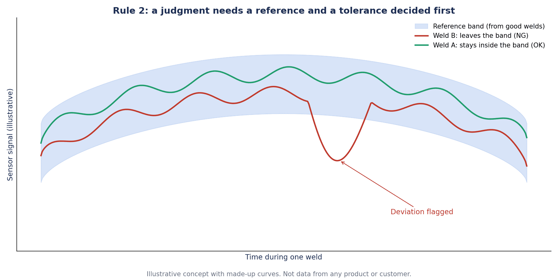
Even once the method is decided, no judgment comes out unless what counts as a good weld is decided. Working with the reference has two aspects: building it and maintaining it.
Building the reference
With either the photodiode or the OCT method, the starting point is to collect “how the signal looks for good welds”. Precitec explains that LWM compares the signal of each weld with predefined reference data. 4D Photonics explains that warning thresholds are adapted to each application. In other words, what can be read from the companies’ explanations is that the reference and thresholds are built for each factory and each part.
When building the reference, looking only at the signal does not tell you whether a weld is good or bad. The Laser Depth Dynamics developers introduced earlier write that photodiode systems need to be trained for each machine by comparison with destructive testing. This statement comes from the developers’ standpoint, but in this article we take the view that, regardless of method, a step is needed in which the signal is matched against cross-section and tensile test results to set the reference. With OCT as well, whether the measured depth matches the penetration seen in the cross-section needs to be confirmed by destructive testing.
When building the reference, you also make welds with deliberately varied conditions. If you observe how the signal moves with defective samples, such as welds with a gap, with the focus shifted or with a contaminated part surface, you become able to explain the basis for the thresholds.
Maintaining the reference
The reference is not finished once it is built. Precitec acknowledges that the signal can shift systematically with a new material lot or changes in part properties, and explains that its software can detect this and adjust parameters automatically without relearning the entire process.
This shows what needs to be decided in the RFP and in operation.
- When the material lot or part supplier changes, who updates the reference, and based on what
- If automatic adjustment is available, how far it is left to automation and from what point a person approves
- Where to keep the history of reference updates (when, who, why)
- After optics maintenance or part replacement, which verification welds confirm that the reference is still valid
Thresholds and the balance between over-detection and missed defects
Tighter thresholds reduce missed defects but increase over-detection, where good parts are judged defective. Looser thresholds do the opposite. The paper by Chianese et al. also states that both false negatives and false positives can occur. How much of each to allow is not decided by technology alone. It depends on whether the defect can be caught in a downstream process, what happens if it reaches the customer, and how much effort it takes to re-judge over-detected parts. The thinking on over-detection and missed defects is also organized in our article on controlling false rejects in AI visual inspection. It is about image inspection, but the way of thinking about setting thresholds is the same.
The figure below illustrates the reference band (envelope) within which good-weld signals fall, and a signal that deviates from it. The waveforms are fictitious, and no numerical values are shown.
Rule 3: Link to the Part ID, Record and Pass to MES
A monitoring judgment does not become a traceability record unless you know which part and which weld it belongs to. The mechanism that links the signal and judgment of each weld to the part ID is an item to decide with the same weight as sensor selection. The overall picture of how to assign and read part IDs is covered in our article on serial number traceability.
The explanations of data integration that we could confirm in each company’s public materials are as follows.
- Precitec: It explains that it stores and documents all relevant process data for each individual part, providing end-to-end traceability of the monitored welding process. It says that combining unique component identification with integration into higher-level production systems forms a basis for quality assurance and process analysis. It states that communication with MES uses OPC-UA and is compatible with TRUMPF QDS and others.
- TRUMPF: In its Smart Services brochure, it explains that Quality Data Storage (QDS) passes structured process and quality data to the customer’s data management system and supports component-related traceability and quality data analysis. The interfaces are OPC UA, fieldbus and digital I/O. The same brochure contains a note on the machines covered by QDS, and the VisionLine OCT Check page separately mentions QDS 2.0. The scope needs to be checked by machine and version.
- Coherent: It explains that Laser FrameWork controls jobs through commands from higher-level systems such as a host or MES, receives product-specific data such as serial numbers, and can collect data for traceability. It lists MQTT, ProfiNet and others as connection methods. OPC UA is not explicitly mentioned on the same page.
- IPG Photonics, nLIGHT plasmo, 4D Photonics: IPG explains that its software catalogs every weld and tracks trends. In the product information on plasmo’s sales site, built-in data storage, a dashboard and traceability documentation are listed. 4D Photonics lists export, analysis and documentation of recorded data.
As an industry standard, a joint working group of the OPC Foundation and VDMA has defined an OPC UA information model for laser systems (OPC 40530 “OPC UA for Laser Systems”). This is an information model of a laser system that includes the laser source and its control, optics, cooling and so on. Whether it is a standard model that handles weld quality monitoring signals and judgments cannot be determined from the abstract we checked. For how to proceed with integration over OPC UA, our article on migrating to OPC UA 1.05 may also be useful.
Where and how much waveform data to store
The design of the storage destination changes depending on whether you keep only the judgment results (OK, NG and feature values) or the waveforms themselves as well. The companies state their sampling frequencies (Precitec’s LWM 8.50 up to 50 kHz, IDM up to 70 kHz, 4D Photonics 100 kHz, and up to 250,000 samples per second according to plasmo’s sales site). However, we could not find any primary source giving guidance on the data volume per weld or the retention period. Data volume varies greatly with the number of channels, weld duration and storage format, so it is an item for vendors to estimate under your own conditions. The thinking on storage destinations for keeping and searching waveforms over the long term is organized in our article on selecting an industrial historian.
How to handle parts judged NG
When monitoring outputs NG, a flow is needed to take the part off the line, hold it, re-judge it and decide on its disposition. Unless the NG signal to the PLC and the rejection mechanism, the record of the held part’s ID and judgment, and the record of the re-judgment result are connected as one sequence, the records will not be connected in day-to-day operation, even if they exist. Holding and quarantine operations are covered in our article on quality hold management systems.
What Standards Define and What They Do Not
We checked the main standards related to laser welding using the abstracts on the official ISO and IEC pages. We have not purchased and read the body of the standards, so we do not deal with the numerical content of their provisions.
| Standard number and edition | Title | What it specifies (official abstract) |
|---|---|---|
| ISO 13919-1:2019 | Electron and laser-beam welded joints — Requirements and recommendations on quality levels for imperfections — Part 1: Steel, nickel, titanium and their alloys | Gives quality levels for imperfections in three levels (B is the most stringent). Thickness 0.5 mm and above. The levels refer to production quality, not to whether the product is fit for its purpose (fitness-for-purpose) |
| ISO 13919-2:2021 | Electron and laser-beam welded joints — Requirements and recommendations on quality levels for imperfections — Part 2: Aluminium, magnesium and their alloys and pure copper | Three levels, thickness 0.5 mm and above. Directly applicable to visual testing. Does not include details of methods for detection or dimensioning by other non-destructive means |
| ISO 15609-4:2009 | Specification and qualification of welding procedures for metallic materials — Welding procedure specification — Part 4: Laser beam welding | Requirements for the content of a welding procedure specification (WPS) for laser welding. Lists the variables that affect the quality and properties of the weld |
| ISO 15614-11:2025 | Specification and qualification of welding procedures for metallic materials — Welding procedure test — Part 11: Electron and laser beam welding | Requirements for welding procedure tests of a WPS. Covers both new fabrication and repair |
| ISO 22827-1:2005 | Acceptance tests for Nd:YAG laser beam welding machines — Machines with optical fibre delivery — Part 1: Laser assembly | Acceptance tests for the laser source, beam delivery system and gas equipment of Nd:YAG laser welding machines with fiber delivery |
| ISO 22827-2:2005 | Acceptance tests for Nd:YAG laser beam welding machines — Machines with optical fibre delivery — Part 2: Moving mechanism | Acceptance tests for the accuracy of two-dimensional moving mechanisms |
| ISO 11553-1:2020 | Safety of machinery — Laser processing machines — Part 1: Laser safety requirements | Laser radiation hazards and safety requirements for laser processing machines, and the information the manufacturer should provide |
| IEC 60825-1:2014 | Safety of laser products — Part 1: Equipment classification and requirements | Classification of laser products by hazard level, information to be provided by the manufacturer, warnings through labels and instructions |
| ISO 3834-1:2021 | Quality requirements for fusion welding of metallic materials — Part 1: Criteria for the selection of the appropriate level of quality requirements | Overview of the ISO 3834 series and criteria for selecting the level of quality requirements |
What can be said from this table is that what the standards define are quality levels for imperfections in welded joints, welding procedures and their testing, acceptance of equipment, safety, and a framework for welding quality management. The abstract of ISO 13919-2 says it is directly applicable to visual testing and does not include details of methods for detection or dimensioning by other non-destructive means. ISO 22827 is a standard whose title refers to Nd:YAG laser welding machines, and whether it applies to machines with other laser sources, such as fiber lasers, cannot be determined from the official abstract.
And in the official abstracts we checked, we found no description of methods or acceptance criteria for in-process monitoring (photodiodes, OCT and so on). Because we have not checked the body of the standards, we cannot state definitively that “there is no provision”, but we think that, at least, the situation is not one in which specifying a standard number decides whether monitoring passes or fails. That is why a realistic approach is to agree with the customer on what monitoring treats as NG, and to verify it at FAT and SAT.
On the safety side, in this article we take the view that checks are needed even when a monitoring device is added later. OCT introduces the measurement beam into the beam path of the processing laser, and photodiodes and cameras are also mounted on or around the optics. If the optics are modified or the procedures for opening and closing the enclosure change, we recommend confirming with the equipment manufacturer from the standpoint of the safety and information requirements of ISO 11553-1 and IEC 60825-1.
The Records and Traceability Customers Require
What the per-weld record is kept for is worked out backward from the customer’s requirements. For automotive parts, the question is how to position weld records within a traceability system that follows customer quality requirements and IATF 16949. The overall picture is covered in our article on IATF 16949 and automotive parts traceability.
In the battery field, moves toward requiring the recording and disclosure of information across the product life cycle are spreading. The EU battery passport is a representative example (article on EU battery passport implementation). However, the battery passport does not require weld monitoring data. We think it is best understood as one context in which record requirements are increasing overall.
In this article, we recommend agreeing on the following points with the customer. This is not the result of checking standards or customer documents but an organization of points as an inference.
- Whether to keep only the judgment result, feature values, or waveforms for each weld
- The scope within which records can be retrieved by part ID (per part, per lot)
- Retention period and storage destination, and the format to provide when the customer requests records
- Disposition of parts that monitoring judged NG, and the record of that disposition
- Whether the customer needs to be notified when the monitoring reference is changed
These may differ from customer to customer. By transferring what has been agreed into the RFP and acceptance criteria, the specifications of the monitoring device and the recording mechanism are connected to the customer’s requirements.
Functions Confirmed in Products
We have listed, in alphabetical order, the functions we could confirm in the public materials of the main vendors. This is not a recommendation or a comparison of superiority. Because what is measured and how it is defined differ from product to product, sampling frequencies and measurement ranges cannot be compared by the size of the numbers.
| Vendor (product) | Method | Main functions confirmed in official information | Stated data integration |
|---|---|---|---|
| 4D Photonics (sales and service by ABICOR BINZEL) | Photodiode | 4D Photonics explains that 4D.TWO samples three ranges, visible, near-infrared and laser wavelength, at 100 kHz and has more than 42 raw channels. It explains that 4D.watcher evaluates with application-specific warning thresholds and classifies defects using combinations of multiple sensors | Export, analysis and documentation of recorded data explained. Communication method not confirmed in official materials |
| Coherent (SmartWeld+, Laser FrameWork) | Sensor set for plasma characteristics and surface temperature (acoustic optional) | Coherent explains that SmartWeld+ uses a sensor set that looks at plasma characteristics and surface temperature, and that an optional acoustic sensor looks at hot cracking and similar defects | Explained as receiving serial numbers and similar data from MES and others and collecting data for traceability. MQTT, ProfiNet and others. OPC UA not explicitly mentioned on the same page |
| IPG Photonics (LDD) | Inline interferometric measurement (OCT type) | IPG explains that a measurement beam in the same optics as the welding beam measures keyhole depth, and also measures seam position, the cross-sectional profile and the bead surface | Software explained as cataloging every weld and tracking trends. Communication method not confirmed in official materials |
| iQLASE (formerly Lessmüller, Blackbird) | OCT, photodiode, camera | In trade media articles, Lessmüller explains that it applies OCT, WELDCHECK (photodiode) and WELDEYE (camera) to battery manufacturing. Blackbird explains that it uses OCT in the three stages of pre, in and post | Not confirmed in official materials |
| nLIGHT plasmo (processobserver) | Diode-based sensor | According to the product information on the sales site, it measures the optical emission of the weld at up to 250,000 samples per second, in three configurations, on-axis, off-axis and integrated into the laser. Has automatic parameter adjustment | According to the product information on the sales site, built-in data storage, a dashboard and traceability documentation |
| Precitec (LWM, IDM) | LWM is photodiode, IDM is OCT | Precitec explains that LWM compares against reference data to detect deviations and can automatically adjust parameters for signal shifts caused by changes in material lot. It explains that LWM AI classifies application-specific defects. It explains that IDM measures weld depth as an absolute value and can control laser power | LWM: TCP/IP, fieldbus, digital I/O, OPC-UA for MES integration (compatible with TRUMPF QDS and others). Per-part data storage explained. IDM: Ethernet, RS422, analog |
| TRUMPF (VisionLine OCT Check, VisionLine Inspect) | OCT, camera | TRUMPF explains that OCT Check measures keyhole depth synchronized with the process and also measures the geometry of the solidified bead with an additional OCT scan. Includes position detection and 3D feature recognition functions. Inspect explained as detecting bead defects with a camera and AI | Explained that data can be stored and retrieved with QDS 2.0. QDS interfaces are OPC UA, fieldbus and digital I/O (machines covered need to be checked) |
Note that iQLASE is a company (Munich) formed by the merger of Lessmüller and Blackbird. Within the scope of our checks, we could not find public prices on the official pages of any of the vendors.
The table lists what we could confirm in public materials and is not the full set of product functions. Also, even if applications such as batteries or hairpins are listed on a product page, the same results will not necessarily be obtained with your own materials and sheet thicknesses. This is an item to verify at FAT, as described in the next section. How to select the welding cell as a whole (robot, fixtures, safety fencing and so on) is covered in our article on welding robot implementation.
RFP Requirements and FAT and SAT Acceptance Criteria
We now translate the three rules so far into an RFP and acceptance criteria. The table below shows examples of items to write in an RFP.
| Item | Examples of what to write in the RFP |
|---|---|
| Defects to find and detection targets | The defect list (Rule 1) and a detection target for each defect. For numerical detection rates and over-detection rates, write the values agreed with the customer |
| Method and mounting position | The proposed method and the basis on which it can detect each defect. Mounting position in the optics, compatibility with the existing welding head |
| Procedure for building the reference | Number of good and defective sample welds, method of matching against destructive testing (cross-section, tensile), how thresholds are set |
| Procedure for updating the reference | Who updates it, when, and what triggers an update. Scope of automatic adjustment and human approval. Storage of update history |
| Handling of material lot changes | Verification welds when the lot changes, detection of and response to signal shifts |
| Output of judgment results | NG signal to the PLC, rejection mechanism, conditions for stopping the line |
| Linking to the part ID | How the part ID is received (from MES, from a reader), linking with the per-weld record |
| Retention period and storage destination | Which of judgments, feature values and waveforms to store, where, and for how many years. Estimate of data volume under your own conditions |
| Interfaces | Methods such as OPC UA and fieldbus, and the data items to be passed |
| Laser safety | Safety checks associated with modifying the optics, division of roles with the equipment manufacturer |
| Training | Training on reading judgments, updating the reference and disposition of NG parts |
FAT (factory acceptance test)
At FAT, you verify whether deliberately made defective samples can be detected. Prepare samples that correspond to the defect list, such as welds with a gap, with the focus shifted, or with a contaminated part surface. At the same time, verify that good parts are not over-detected. It is important to make both finding defects and passing good parts conditions for acceptance. How to proceed with ordering and acceptance testing of inspection equipment is also organized in our article on inspection equipment automation.
SAT (site acceptance test)
At SAT, you operate the system under mass production conditions for a certain period and match the judgments against destructive testing results. During this period you also verify how the signal moves when the material lot changes and whether the reference update procedure works. You also confirm that the link to the part ID is recorded without gaps and can be retrieved from MES or the storage destination.
We do not recommend a specific numerical detection rate target here. It varies with the importance of the part, whether defects can be caught downstream, and the customer’s requirements. The approach is to write “the value agreed with the customer” in the RFP and acceptance criteria, and to verify that value at FAT and SAT.
Cost and Benefit Model Estimate (Hypothetical Figures)
The following is an estimate using hypothetical figures prepared for this article. The assumption is a Japanese-affiliated battery module assembly factory in Thailand (or an electric component factory) with one laser welding line for busbars and tabs. Quality is currently checked with sampling-based cross-section checks, tensile tests and visual inspection.
The loss assumptions are as follows. Outflow to the customer and internal rework are counted as separate events. The same defect is not counted twice.
| Item | Assumption | Amount (THB/year) |
|---|---|---|
| Handling of claims for weld defects that reached the customer (sorting, returns, investigation) | 4 cases per year × 250,000 THB | 1,000,000 |
| Scrap and rework of weld defects found in internal downstream processes (electrical testing and so on) | Assumption | 440,000 |
| Total | 1,440,000 |
The countermeasures are the introduction of in-process monitoring, procedures for building and updating the reference, and linking to the part ID with MES integration.
| Item | Amount (THB) |
|---|---|
| Sensors and integration into the optics | 1,000,000 |
| Trial welds and destructive testing for building the reference | 300,000 |
| Part ID linking and MES integration | 300,000 |
| Training and FAT, SAT | 200,000 |
| Total initial cost | 1,800,000 |
| Annual operating cost (maintenance, reference updates, data storage) | 120,000/year |
The estimated effect is as follows.
| Case | Loss reduction | Annual effect | Annual net effect | Payback period |
|---|---|---|---|---|
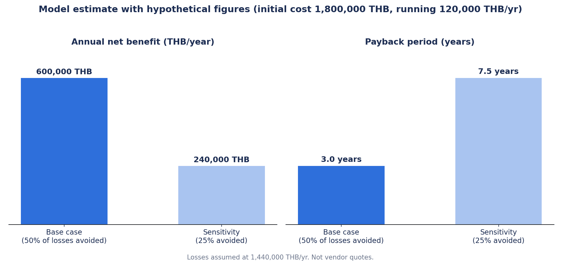
| Base case | 50% | 1,440,000 × 50% = 720,000 THB | 720,000 − 120,000 = 600,000 THB | 1,800,000 ÷ 600,000 = 3.0 years |
| Sensitivity (effect is one quarter) | 25% | 1,440,000 × 25% = 360,000 THB | 360,000 − 120,000 = 240,000 THB | 1,800,000 ÷ 240,000 = 7.5 years |
Here is how to read this estimate.
- The effect ratios (50% and 25%) are assumptions. The actual effect depends on which defects monitoring can find and on what is done after they are found.
- In this article, we think that what has the greatest effect is building the reference in Rule 2. If the good-weld reference is not decided, monitoring leans toward either over-detection or missed defects. If it leans toward over-detection, re-judgment and scrapping of good parts increase. If it leans toward missed defects, outflow to the customer does not decrease.
- If the customer makes per-weld records a condition of business, that value (keeping the orders) is not included in this estimate.
- Before implementation, we recommend counting the number of weld defects over the past 12 months (separately for the customer and internally) and the cost of sampling inspection. Replacing the assumptions of the estimate with your own figures gives a basis for the decision.
- It is safer not to count any effect until FAT, SAT and three months of operation have confirmed that deliberately made defective samples can be detected and that over-detection is low.
A supplementary note on cost. We could not find public prices on the official pages of the main vendors (Precitec, IPG, TRUMPF, plasmo, 4D Photonics, Coherent, iQLASE). No price is listed on plasmo’s sales site either. Prices are likely to vary greatly depending on the configuration of method, number of channels, integration into the optics, software and data integration. The initial cost above is only a placeholder for the estimate, and the actual amount should be confirmed by obtaining quotations through an RFP.
Frequently Asked Questions
What is laser welding monitoring?
It is a mechanism that uses sensors to observe the state of the weld before, during and after laser welding and judges whether it is good or bad. Before welding it looks at the seam position and joint geometry, during welding at the light emitted by the process and the keyhole depth, and after welding at the bead geometry. The focus of this article is monitoring during welding (in-process), for which there are three methods: photodiode, OCT and camera.
What is the difference between OCT and photodiodes?
The photodiode method is a correlation-based judgment that receives the light emitted by the process during welding (plasma light, thermal radiation, reflected light), compares it with reference data and finds deviations. The OCT method introduces a dedicated measurement beam into the beam path and measures the keyhole depth and similar values through interference. Because they look at different things, the starting point is to choose based on the defects you want to find. Both require the good-weld reference to be decided first.
Can penetration depth be measured with OCT?
Research and the companies’ explanations say that in-process monitoring of penetration depth with OCT is possible. However, there are conditions on positioning of the measurement spot and on the measurement range, and research on copper reports a tendency to underestimate depth in unstable deep penetration welding. We recommend not assuming that keyhole depth and penetration depth are the same, and verifying by matching against destructive testing.
How should battery tab welds be inspected?
For tabs and busbars, the main candidates are lack of bonding caused by gaps, contamination on the part surface, and insufficient penetration. In a study of copper-steel tabs, variation in the gap could be diagnosed from step changes in the plasma light and temperature signals. However, this is a result for a specific material and sheet thickness. The sequence is to make defective samples with your own parts, build the reference by matching signals against cross-section and tensile results, and keep the judgment of each weld linked to the part ID.
Are acceptance criteria for monitoring defined by standards?
In the official abstracts of ISO 13919 and the other standards we checked, we found no description of methods or acceptance criteria for in-process monitoring. Standards define quality levels for imperfections in welded joints, welding procedures and their testing, acceptance of equipment, safety and so on. We think a realistic approach is to agree on the acceptance criteria for monitoring with the customer and verify them at FAT and SAT.
How should weld data be stored and linked to parts?
Receive the part ID from MES or a reader, and store the judgment and feature values of each weld (and waveforms if needed) together with that ID. The companies explain integration over OPC UA, fieldbus and other methods. Because we could not find industry guidance on data volume per weld or retention period, have vendors estimate under your own conditions, and decide the storage destination and retention period according to the customer’s requirements.
How much does laser welding monitoring cost?
We could not find public prices on the official pages of the main vendors. Cost varies with the configuration of method, number of channels, integration into the optics, software and data integration. In this article’s hypothetical estimate, we set the initial cost at 1,800,000 THB and the annual operating cost at 120,000 THB, giving a payback of 3.0 years if half of the losses are reduced and 7.5 years if one quarter is reduced. The actual decision should be based on your own defect counts and RFP quotations.
Summary
- What to decide first when implementing laser welding monitoring is not the type of sensor but three things: (1) the defects you want to find, (2) how to build and maintain the good-weld reference and tolerance range, and (3) linking to the part ID and where records are passed.
- The photodiode method is a correlation-based judgment that compares process light with a reference, and the OCT method measures depth with a measurement beam. OCT also has conditions: the position of the measurement spot, the measurement range, and underestimation in unstable welds.
- Choose the method from the defect and cause table. Lack of bonding and insufficient penetration that do not appear on the surface are defects that are hard to cover with visual inspection alone.
- Build the reference by matching against destructive testing, and write into the RFP the procedure for updating it in response to changes such as material lot changes.
- Only when the judgment of each weld is linked to the part ID and connected through to MES, the storage destination and the hold operation for NG parts does it become a traceability record.
- In the official abstracts of the standards we checked, we found no acceptance criteria for in-process monitoring. Agree on acceptance criteria with the customer and verify them at FAT and SAT.
- In the hypothetical estimate, payback is 3.0 years if half of the losses are reduced and 7.5 years if one quarter is reduced. A good first step before implementation is to count defects over the past 12 months, separately for the customer and internally.
TOMAS TECH can help from an early stage of your study, such as deciding which defects of which welds to monitor first, how to make defective samples, and how to design the link to part IDs and MES integration. You are welcome to contact us even before the method or product has been decided. Please contact us here.
References
- Precitec, “Laser Welding Monitor LWM”
- Precitec, “Precitec IDM (Welding depth measurement)”
- IPG Photonics, “Real-time laser weld measurement (LDD)”
- Chianese et al., “Characterization of Photodiodes … Copper-to-Steel Battery Tab Connectors,” ASME JMSE 144(7), 2022 (WRAP open version)
- Will et al., “Algorithms for Weld Depth Measurement in Laser Welding of Copper with Scanning OCT,” Micromachines, 2022
- Laser Focus World, “Monitoring laser welding,” 2005
- Laser Focus World, “Direct measurement of laser weld depth with inline coherent imaging,” 2015
- The Laser User Issue 92, “Laser Welding Using Optical Coherence Tomography,” 2019 (PDF posted by Precitec)
- AMADA WELD TECH, “Laser Welding Metals: Troubleshooting 4 Common Issues,” December 13, 2024
- TRUMPF, “new TRUMPF solution boosts welding quality and efficiency,” June 24, 2025
- TRUMPF, “VisionLine OCT Check”
- bbr, “Remote Laser Welding: Real-Time Control and Inspection,” March 4, 2026
- Wiley Industry News, “Smart monitoring of battery welding processes,” 2021
- hyfindr, “processobserver – Online Process Monitoring” (nLIGHT plasmo product listing)
- Baader et al., “Potentials of OCT for Process Monitoring in Laser Welding of Hairpin Windings,” EDPC 2021 (FAU CRIS)
- Wirtschaftsforum, “iQLASE GmbH”
- ABICOR BINZEL, “Laser process monitoring WeldWatcher” (4D Photonics)
- Coherent, “Laser FrameWork Integration & Connectivity”
- ISO, “ISO 13919-1:2019”
- EVS, “ISO 13919-1:2019” (bibliographic record)
- ISO, “ISO 13919-2:2021”
- ISO, “ISO 15609-4:2009”
- ISO, “ISO 15614-11:2025”
- ISO, “ISO 22827-1:2005”
- ISO, “ISO 22827-2:2005”
- ISO, “ISO 11553-1:2020”
- IEC Webstore, “IEC 60825-1:2014”
- ISO, “ISO 3834-1:2021”
- TRUMPF, “Smart Services laser systems” (brochure PDF)
- OPC Foundation, “OPC 40530 OPC UA for Laser Systems”
- Placera, “Bilproduktionen i Thailand ökade nära 11 procent i augusti,” September 28, 2026
- NST, “Thailand car production rises 6.1pct on year in July,” August 25, 2026
- The Nation, “Thailand EV investment tops 137bn baht as BOI targets ASEAN hub,” July 3, 2026
- Just Auto, “Thailand approves Sunwoda’s $1bn EV battery cell production facilities,” March 13, 2025
- Just Auto, “Svolt starts EV battery production in Thailand,” March 1, 2024


