



When introducing AI quality control for weld bead inspection, the first decision is not about the type of AI model. It is about which joint, which surface, which type of defect to detect, the criteria for pass/fail judgment, and how to handle invisible defects. This article concretizes the process from Request for Proposal (RFP) to Factory Acceptance Test (FAT) and Site Acceptance Test (SAT) for quality assurance, welding technology, production engineering, and control personnel procuring image inspection cells at factories in Thailand. Numerical examples are design samples and do not represent uniform standards or guaranteed performance.
Key Takeaway: Contract AI Quality Control for Weld Beads Based on the “Scope Visible in Images”
Welding quality involves separate questions about surface shape, internal condition, and strength-related process parameters. Cameras capture only surfaces illuminated and visible to the lens. While image inspection can detect sudden changes in bead width, excessive convexity, undercut-like contours, surface holes, or spatter, it cannot guarantee internal lack of fusion or internal porosity by image alone. Therefore, the RFP must specify “detectable defects” and, with the same granularity, “undetectable defects.” Leaving the latter blank risks the dangerous interpretation post-installation that “if AI says OK, the entire weld is accepted.”
Factories purchase not just the classifier but the entire inspection process including workpiece positioning, imaging, judgment, segregation, re-inspection, and record keeping. Acceptance testing must verify everything affecting pass/fail decisions in a single test: image clarity, product ID linkage, PLC output, and procedures for power or communication failures. Narrowing the initial scope to one product group, one joint type, and one imaging surface simplifies decision-making. Expanding scope should follow after measuring both misses and false positives in that process.
General camera, lighting, and model selection are covered in the AI Visual Inspection Implementation Guide. Automatic welding condition generation and robot path correction are topics in the AI Welding Robot Implementation Article. This article focuses on procuring and verifying the inspection process that accepts the finished weld bead.
Separate Reading of Standards, Drawings, and Customer Requirements
Simply stating “ISO compliant” in welding inspection does not define judgment criteria. ISO 5817:2023 specifies quality levels for imperfections in fusion-welded joints of steel, nickel, titanium, and their alloys within its scope. It defines three levels: B, C, and D, with B being the most stringent. An observed imperfection is not automatically a rejectable defect; acceptance depends on the adopted quality level, dimensional limits, drawings, and contract requirements. However, which level applies to a product must be defined by design, contract, or applicable standards. If material, thickness, joint, welding method, or inspection scope is excluded, do not mechanically apply the standard number for automated judgment.
ISO 17637:2016 covers visual testing of fusion joints in metallic materials. The current edition, confirmed in 2022, is published by ISO. Since image inspection cells handle only visible surfaces, this standard serves as a reference, but placing a camera alone does not automatically satisfy its test method requirements. Specify imaging directions, pre-observation conditions, inspector roles, and recording methods. ISO 17635:2025 provides general rules for selecting and evaluating non-destructive testing (NDT) methods for metal welding, explaining that quality levels and individual NDT acceptance levels cannot be equated directly. This is why surface image results and UT/RT/PT/MT results are not combined into a single defect rate.
If AWS D1.1 is specified in structural steel contracts, the quality assurance department must identify the adopted edition and relevant clauses, including whether the contract specifies the 2025-AMD1 Amendment 1. The official AWS D1.1 guidance explains that the 2025 edition covers construction, inspection, and acceptance criteria and applies when adopted contractually. Before creating a custom “AI standard” mixing ISO and AWS, clarify which takes precedence. This article does not provide uniform defect dimension criteria applicable to all products. The final judgment table must be linked to actual contract documents, product drawings, and approved welding procedures.
Define AI Weld Defect Detection Scope with Five Key Questions
- What is the unit of work?
Beyond product number, joint number, weld pass, front/back side, and start/end positions must be identifiable to avoid mixing multiple beads of the same product.
- Which area is inspected?
Define imaging areas on drawings: bead crown, termination, fixed width on base metal side, crater, etc.
- Which phenomena are detected?
Link surface openings (holes), crack-like linear indications, undercut-like depressions, excess reinforcement or width changes, spatter adhesion, etc., to site judgment terms and sample images. If defect names cannot be conclusively assigned by appearance alone, mark as “requires confirmation.”
- What happens after judgment?
Prepare three routes: pass flows through, fail is segregated, and indeterminate goes to REVIEW. REVIEW is not a container to hide poor accuracy. Define reviewer, time limits, final judgment, and physical storage location.
- What is the boundary of image inspection?
Explicitly exclude back sides, shielded terminations, internal defects, and properties only determinable by strength tests. Decide in the quality plan whether to retain necessary NDT or destructive tests.
Agreeing on these five questions upfront enables vendors to provide realistic estimates based on actual products rather than abstract promises like “99% detection rate.”
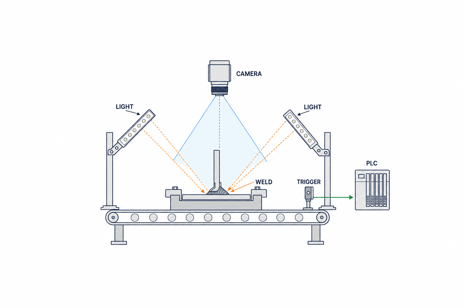
Imaging Cell Design: Decide Workpiece, Lighting, and Distance Before Cameras
Weld metal surfaces exhibit gloss, oxidation colors, spatter, oil, and heat discoloration. Even good beads vary greatly by welding method and posture. Shadows can appear as depressions depending on lighting direction. Test candidates include ring light, oblique light, coaxial light, and diffuse light, rotating and repositioning actual workpieces to verify reproducibility. If necessary, compare two-direction imaging or 3D shape measurement. When estimating height from 2D images, specify the estimation limits in the RFP.
Wider fields of view increase coverage but reduce pixels per minimum indication. Selecting by pixel count alone ignores lens resolution, depth of focus, shutter, lighting, and workpiece posture errors that degrade effective performance. Specify “minimum visually detectable change,” “required field of view,” “allowed position deviation,” and “imaging time window,” then require vendors to perform optical verification on actual workpieces. If dimensional thresholds are judged by images, include calibration procedures and measurement uncertainty.
Appearance changes depending on whether imaging is done immediately after welding or after cooling. Record site conditions including fumes, dust, debris, jig shadows, and arc light afterglow. Some disturbances can be mitigated by enclosing the inspection cell. The more stable the imaging conditions before model training, the fewer unnecessary variations the model must learn. Conversely, designs requiring retraining whenever imaging conditions change increase maintenance burden and quality responsibility.
Training Data: Judgment Basis and Separation Method Matter More Than Number of Defect Images
AI training images require more than just sorting into good and defective folders. Include workpiece ID, joint ID, material, thickness, welding method, process conditions, imaging conditions, defect location, referenced standard/version, inspector, and re-inspection history. Separate the phenomenon visible in the image from the final pass/fail judgment. For example, spatter may be visible but acceptable per product acceptance criteria. This prevents confusing what the model “sees” with contractual “fail” decisions.
When splitting images for training, threshold tuning, and final evaluation, ensure continuous frames of the same workpiece, cutouts of the same bead, or re-imaged photos do not overlap between sets. Random product splits can still leak nearly identical images into training and testing, overestimating field performance. Include day/night shifts, pre/post maintenance, lots, material lots, jig changes, operators, and welding machines in evaluation sets. If rare critical defects are insufficient, mark as “validation incomplete” and do not claim acceptance performance.
The NIST AI RMF MEASURE framework requires documentation of test sets, evaluation metrics, test methods, and performance measurement under conditions similar to deployment. Practically, weld AI must seal evaluation sets traceable to “what was measured on which images.” NIST does not specify numeric targets here; the factory decides based on product risk and re-inspection capability.
Metrics: Count Misses and False Positives Separately
A single confusion matrix for the entire product averages out critical defect misses. Key metrics are miss counts and total defect counts per defect type, severity, joint type, and imaging surface. Simultaneously, report counts of good products sent to NG or REVIEW and total evaluated good products. Counting REVIEW as “correct” hides the human re-inspection burden. Report the three routes’ counts as-is.
| Metric | Numerator ÷ Denominator | Meaning on Site |
|---|---|---|
| Miss Rate | Number of failed products passed ÷ total failed | Risk directly linked to customer escapes |
| False Positive Rate | Number of good products sent to NG or REVIEW ÷ total good | Impact on re-inspection workload and yield |
| Imaging Failure Rate | Number of images that cannot be judged ÷ requested images | Stability of optics, triggers, contamination |
| Traceability Loss Rate | Number of unlinked ID/image/result ÷ total judged | Usability as quality record |
| Response Time | Measured time from trigger to PLC reception | Can segregation occur within takt time? |
Acceptance thresholds consider customer requirements, historical escapes, defect severity, re-inspection capacity, and statistical uncertainty. For example, zero misses in a small sample does not prove 99.9% detection. Observed zero and verified rare defect detection are distinct claims. For low-defect classes, add samples, intentional test pieces, independent inspection methods, or double human checks. If statistical confidence levels are contractual, design sample sizes with quality/statistics teams.
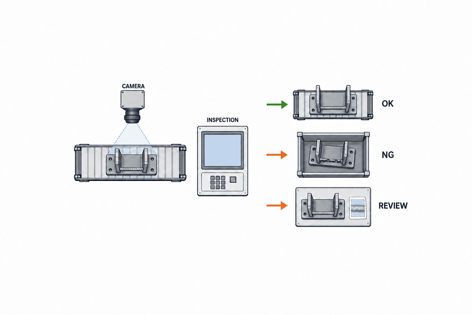
Attach Judgment Tables, Cell Configuration, and Data Rights to RFP
Sending vendors only “We want AI inspection of weld beads” results in quotes ranging from camera suppliers to full quality record providers. To compare fairly, separate RFP text and attachments. Judgment tables specify product groups, materials, joints, inspected surfaces, defect candidates, reference standards/versions, drawing numbers, quality levels, decision authority, and REVIEW conditions. Use official defect classification terms from sources like the ISO 6520-1:2007 ISO catalog and provide correspondence tables to site colloquial terms. Using only colloquial labels risks inconsistent naming across departments for the same image.
Cell configuration diagrams show transport direction, workpiece fixation, camera line of sight, lighting, trigger sensors, encoders, PLC signals, NG ejection points, and emergency stop boundaries. Break down takt time into imaging, transfer, inference, judgment, PLC response, and ejection measured or design values. Fast AI inference alone is insufficient if signals do not reach before ejection position. Quality decides whether failures default to auto-OK, line stop, or REVIEW and specifies I/O accordingly.
Data contracts cover ownership, access rights, storage location, retention period, and transfer format for raw images, judgment images, labels, models, thresholds, recipes, and logs. If cloud use is involved, confirm transmission targets, network outage behavior, cross-border storage, and customer image handling. Decide model retraining rights, data extraction on vendor change, security updates, and remote maintenance access before quoting. Do not compare only initial price; request total cost including adding product types, lens/lighting replacement, annual maintenance, and re-evaluation.
Compare Quotes Using the Same Test Pieces and Failure Conditions
Distribute not only “clean representative photos” but also real or image data including borderline cases for vendor comparison. Include good product variation, each defect class, ambiguous judgments, oil films, oxidation colors, repositioning, jig errors, and imaging failures. Manage separately the data given to vendors for tuning and the unpublished data reserved for final evaluation. Acceptance testing on images used for tuning diminishes comparison validity.
Require vendors to explicitly state out-of-scope conditions. Statements like “internal defects cannot be detected from images,” “rotation jig needed to image back side,” or “inspection only after surface cools” are not deductions but valuable cost transparency. Evaluation criteria include detection performance, handling of uninspectable cases, maintenance/calibration, local recovery capability, data transfer, and re-test scope on changes. For Thai factories, also compare who locally can restore jigs, lighting, and PCs within what time and whether procedures are provided in the local working language.
Exercise caution when fabricating test pieces or adopting simulated defects. The “defect-like appearance” shown to the model may not match actual defects causing rejection in real products. Specify in the RFP that simulated samples are for functional testing only and not proof of detection performance on real defects. When correlating destructive tests or NDT with images, record who approved the final ground truth.
Keep PoC Small; FAT and SAT Verify Different Questions
The Proof of Concept (PoC) aims to expose major risks to decide adoption. Confirm at minimum imaging reproducibility, visibility of target defects, good product variation, miss and false positive trends, REVIEW volume, and takt time. Deliverables are not demo videos but sample lists, imaging conditions, models/thresholds, confusion matrices, failure images, and failure reasons. If results are insufficient, allow decisions to “improve and retest,” “compare alternative optics,” “change target joint,” or “not adopt image inspection.”
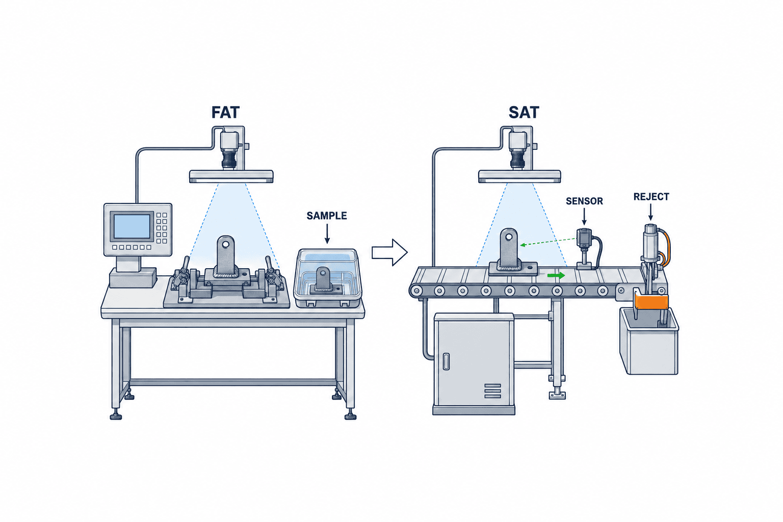
FAT is pre-shipment inspection using agreed equipment/software configuration and sealed test sets. Verify cameras, lenses, lighting, jigs, PLC simulators, reject signals, logs, permissions, backup/recovery, and communication failure behavior. Fix versions, recipes, checksums, and equipment numbers passing FAT and record changes until SAT. Do not conclude FAT solely on AI model accuracy.
SAT is conducted on the actual line, integrating product transport, vibration, shifts, cleaning, changeovers, ambient light, and network. If factory temperature or lighting differs from FAT, image distributions change even for the same bead. Record unverified conditions by name and limit acceptance scope. For example, “Product A front side, day shift, jig R2 passed” does not mean “usable for all products and shifts.” Before full inspection, run parallel operation, record differences with human judgment, and have quality assurance arbitrate discrepancies.
Make Acceptance Test Procedures “Repeatable by Anyone”
At the start of the test procedure document, specify target products, joints, versions, equipment configuration, imaging recipes, allowable environment ranges, pass/fail thresholds, test data sealing method, and responsible personnel. Prepare good, defective, and imaging failure samples with IDs in advance and randomize order. Save settings at test start to prevent vendors adjusting thresholds after viewing images. If adjustment is needed, conduct a new test version without overwriting old results.
Record per case: image ID, workpiece ID, joint position, ground truth basis, AI score, output (OK/NG/REVIEW), PLC reception time, ejection result, and re-inspection result. Tabulate numerator and denominator per defect class; do not decide acceptance by a single average accuracy. Include test cases for imaging failure, wrong product recipe, model load failure, full storage, communication loss, and power recovery. Since safety functions and quality judgments have separate design responsibilities, do not substitute AI pass for machine safety verification.
For failures, isolate causes: equipment malfunction, imaging conditions, label conflicts, standard interpretation differences, or model limitations. Without saving images and physical samples, recording only “AI misjudged” prevents improvement. Agree on data for retesting, correction scope, judgment responsibility, and delivery deadlines. Detailed acceptance test sheets enable re-testing by other inspectors later, useful for vendor changes or model updates.
Post-Deployment Change Management: Suspect Imaging Conditions Before the Model
Performance degradation after deployment is not always due to model obsolescence. Lens dirt, lighting deterioration, jig wear, material surface changes, welding condition changes, or camera misalignment alter physical inputs. Daily startup checks should include re-imaging reference workpieces, lighting/focus confirmation, time synchronization, and NG ejection tests. Regularly monitor REVIEW and imaging failure rates by product and shift; investigate sudden changes on site.
Do not treat threshold changes, recipe changes, retraining, and camera replacement as the same “fine-tuning.” Define affected joints/defect classes and re-test scope per change, record approvers and rollback procedures. When adding operational NG data to training, verify human arbitration correctness and that classification has not changed post-customer release. Automatic retraining on incorrect labels risks normalizing defects. The NIST MEASURE Playbook also addresses ongoing monitoring and re-evaluation considering data distribution shifts.
For audits, enable searching original images, results, model/threshold/recipe versions, product IDs, inspection times, operator overrides, and final disposition at judgment time. Retention periods align with customer contracts and internal quality policies. “OK counts” without traceability cannot verify claims if complaints arise later. Investment evaluation for inspection automation must include inspector time, re-inspection, false rejects, changeovers, maintenance, and data storage costs.
“`markdown
FAT/SAT Stratify Defects and Field Conditions, and Test Measures for Missed Detections
If acceptance test samples are defined simply as “100 good products and 100 defective products,” there may be only a few instances of difficult joints or critical surface indications included. The test matrix stratifies samples by product group, joint type, plate thickness range, welding method, front/back side, bead start/steady/end positions, defect candidates, and severity. For each stratum, the number of actual samples prepared, the basis for ground truth, image acquisition feasibility, and OK/NG/REVIEW results are recorded. Strata without samples remain blank and are marked as “untested.” Strata with zero misses must not be grouped in the same pass category as those not yet tested. To avoid giving the impression of high confidence from a small sample ratio, both the rate and the raw number of samples are shown.
During FAT, the same test piece is repeatedly mounted and imaged to verify restoration of lighting settings, recipe switching, and reference workpiece confirmation after camera replacement. SAT stratifies conditions as much as possible by day shift versus night shift, low speed versus rated speed, before and after fixture replacement, immediately after cleaning versus progressively soiled states, and normal transport vibrations. If all conditions cannot be covered in a single day, the acceptance record separately documents tested operating ranges, untested conditions, and schedules for additional testing. Numerical values confirmed during PoC or FAT are not directly transferred as SAT results on site. The acceptance range is determined solely from local data, and workpieces outside this range are routed for human inspection.
Procedures for handling missed detections discovered during testing are also established separately from the performance table. The relevant actual items and the same-condition lot since the last confirmed normal check are temporarily isolated, and quality assurance determines the scope of reinspection. The vendor submits images, scores, model versions, imaging conditions, and PLC output logs to assist in root cause analysis. Line personnel follow equipment stop and restart procedures, and quality assurance decides on product shipment eligibility. Isolated products must not be automatically reinstated as acceptable solely by vendor model revisions. After corrections, retesting is conducted using the same failure examples plus independent samples to verify that performance on other defect classes has not deteriorated.
“`
Specify the “Inspection Operation Ledger” to Be Handed Over After Acceptance in the RFP
Simply handing over the AI model files at delivery is insufficient for the factory to maintain the inspection process. The operation ledger consolidates the applicable scope for each product and joint, imaging recipes, lighting and camera settings, reference workpieces used for calibration, the latest judgment tables, versions of models and thresholds, approvers, original records of FAT/SAT, unverified conditions, known misjudgments, and periodic inspection cycles. Work procedures that enable decisions such as “clean this type of dirt” or “stop if this positional deviation occurs,” accompanied by photographs, are also necessary. If shift workers on site only have procedure manuals in languages they cannot read, they will not be able to correctly switch to REVIEW mode in the event of a malfunction. It is confirmed during SAT that the screen displays and procedure manuals match in both Thai and the factory’s common language.
The responsibility allocation for the ledger is also a contractual condition. Quality assurance approves the judgment criteria and permissible changes; production engineering maintains the condition of jigs and optical systems; IT/OT manages time synchronization, networks, storage locations, and access rights. The vendor specifies the scope of maintenance, contact routes in case of failures, and re-verification procedures after recovery. When registering new product types, it is not sufficient to simply “add a few images for training”; instead, joints, surfaces, defect classes, and process conditions must be added to the ledger, and the affected acceptance tests must be repeated. It is also necessary to verify that model updates do not degrade judgments for older products. Predefining procedures for reverting to previous versions and handling manual inspections during that period prevents update operations from becoming high-risk gambles for quality.
Inspection histories are also used for complaint handling. When a customer points out a specific lot, it must be possible to trace the workpiece ID, joint ID, original images, judgment versions, REVIEW rulings, and equipment inspection history for that period. Relying solely on timestamps during extraction risks mix-ups due to clock differences between PLCs and PCs. The system should be designed to allow searches by both ID and timestamp, and the occurrence of missing records should be monitored as an operational indicator. These are quality record requirements separate from AI model performance and are more reliably specified in the RFP at the time of introduction than added later.
Pre-Order Checklist for Thai Factories
In ordering meetings, aim to answer these questions in writing:
- Are applicable contract, drawing, and standard versions and priorities decided?
- Are defects visible in images separated from those requiring other NDT or tests?
- Are products, joints, imaging surfaces, and shifts limited?
- Are OK/NG/REVIEW and stop behaviors decided?
- Has optical testing on actual workpieces been done?
- Are training and final evaluation samples separated?
- Are denominators for misses and false positives defined?
- Are conditions separately verified in FAT and SAT clarified?
- Are raw images, models, and logs transfer and maintenance rights decided?
- Are local recovery personnel and working languages in Thailand decided?
Any blank among these ten questions still allows image capture and trial, but AI models cannot fill contractual, acceptance, and operational ambiguities. Starting with small optical tests, creating workpiece-to-standard correspondence tables, sealing evaluation sets, and proceeding under agreed acceptance conditions reduces detours. Designing to correctly stop uninspectable cases is more valuable to quality departments than prematurely claiming high detection rates.
Frequently Asked Questions
Can internal defects be detected by weld bead image inspection alone?
Normal surface camera images cannot directly confirm internal lack of fusion or internal porosity. Surface indications may correlate with internal conditions, but without independent verification on specific products, image AI cannot replace internal defect inspection. Select necessary NDT per applicable standards and quality plans. The RFP must state these limitations and handover to other processes.
Is “99% accuracy” in weld defect AI detection sufficient as acceptance criteria?
Without defining denominators, defect types, severity, good product variation, and handling of indeterminate cases, “99% accuracy” is insufficient. Combining critical defect misses and minor appearance false positives into one metric cannot assess quality risk. Contract class-specific counts, reliable ground truth, sealed test sets, and REVIEW handling must be included.
Which is better for welding inspection automation: rule-based or AI?
If targets like width or position are stable and measurable, rule-based methods may be preferable for explainability and maintenance. For complex shapes and large good product variation, consider AI. Hybrid approaches use rules for positioning and dimension measurement, AI for appearance judgment. Do not fix method names upfront; compare under identical conditions and analyze failure reasons per defect class.
Can Thai factories switch immediately to 100% inspection after passing FAT?
FAT verifies equipment conditions pre-shipment. Local vibration, ambient light, transport, changeovers, shifts, and ejection mechanism integration are verified in SAT. Switch only after defining SAT acceptance scope, parallel operation period, and human re-inspection. Adding product types or joints requires re-evaluation.
Summary
In AI quality control for weld beads, fix first the applicable standards and contractual acceptance criteria, the visible scope in images, excluded internal defects, and OK/NG/REVIEW handling. Use actual workpieces and borderline cases as common conditions in RFP. Confirm configuration and sealed data in FAT, and local transport, environment, and stop behavior in SAT. Counting misses, false positives, imaging failures, and traceability losses separately enables quality managers to explain adoption decisions.
At TOMAS TECH, we consult from the stage of joint scope separation, imaging cell configuration, RFP items, and acceptance test sheets for welding inspection at Thai factories. If you have current drawings, inspection standards, and conditions of workpieces to image, please first share your challenges via Contact Us.
References
- ISO 5817:2023 — Quality levels for imperfections in fusion welds (ISO, check scope and B/C/D levels)
- ISO 17637:2016 — Visual testing of fusion welds (ISO, current edition and scope)
- ISO 17635:2025 — General rules for NDT of metallic welds (ISO, inspection methods and acceptance levels)
- ISO 6520-1:2007 — Classification of geometric imperfections in welding (ISO catalog, current edition)
- AWS D1.1/D1.1M:2025-AMD1 — Structural Welding Code—Steel (AWS, scope and contractual adoption)
- NIST AI RMF — MEASURE (NIST, documentation of test sets, metrics, and operational conditions)
- NIST AI RMF Playbook — MEASURE (NIST, ongoing monitoring and re-evaluation concepts)
*Contractual clauses and customer agreements take precedence. The linked summaries do not replace official standards. Confirm adopted versions, judgment values, and inspection scopes per project.*


