


Will a motor stop command protect a drive train when a conveyor jams? The PLC, drive and brake all need time to react; a shaft, gearbox or fixture may already have seen excessive load. A mechanical torque limiter can address a defined overload at a defined location. Selecting one involves more than matching a catalogue torque range. Engineers must establish the normal torque peaks, the limit of the component being protected, the mechanical behaviour after release, how the controller detects and stops the drive, and how the system will be tested. This guide is written for procurement, maintenance and machine engineering teams commissioning automated equipment in Thailand.
Start torque limiter selection with the component to protect
A torque limiter sits in the power path between a driving and a driven element. Depending on its mechanism, an overload may cause controlled slip, ratcheting or separation of the input and output. Mayr distinguishes load-holding designs, which continue transmitting limited torque, from load-separating designs, which interrupt transmission. These are different operating behaviours, even if both are sold as torque limiters or overload clutches.
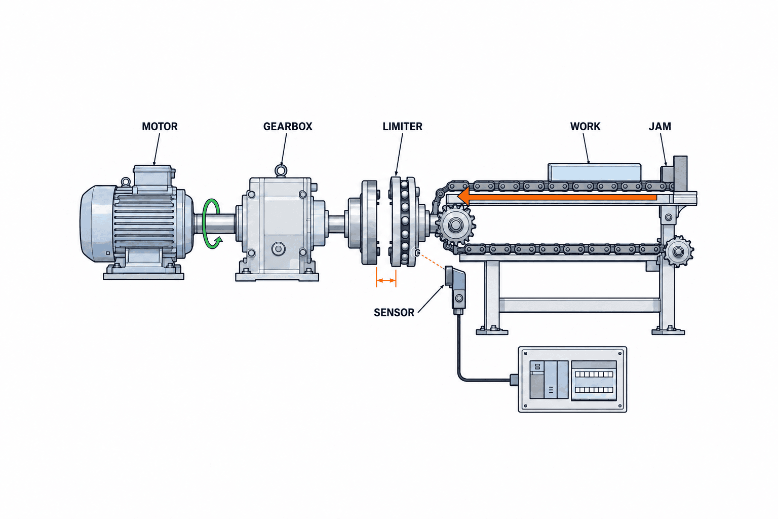
Write down the failure you intend to prevent before selecting a part number. Is the weak element a gearbox output shaft, conveyor chain, indexing fixture, screw feeder or workpiece? A limiter placed at the motor side does not see the same torque or speed as one placed after the reducer. Draw the complete path from motor and brake to reducer, coupling, limiter, belt or chain, fixture and product. Our shaft coupling selection guide explains shaft connection and misalignment; our gearbox reducer guide covers reduction and output capacity. The distinct question here is what moves, disengages and stops when an obstruction occurs.
| Decision | Site question | Documented output |
|---|---|---|
| Protected item | Which shaft, gear, tool or product must survive the fault? | Weakest element and allowable load |
| Fault | Is the event a jam, collision, wrong feed or lost synchronization? | Reproducible scenario and expected frequency |
| Position | Where can the limiter fit and be serviced? | Shaft diameter, hub, flange and access drawing |
| Normal operation | What are the real acceleration and process peaks? | Measured torque or justified envelope |
| After release | May the drive slip, ratchet or freewheel? | Stop logic, reset authority and restart conditions |
| Acceptance | What result proves the design works? | FAT and SAT conditions and pass criteria |
A limiter is not, by itself, a complete personnel safety system. Guards, interlocks, emergency stops and hazardous-energy isolation are selected through the machine risk assessment. Keep the product-protection objective separate from human safeguarding while designing their interactions.
Measure the normal torque envelope before choosing a setting
A motor nameplate does not describe every torque on the protected shaft. Starting, accelerating, stopping, reversing, full-load and empty operation, changing product friction and a sudden feed can all create peaks. For a servo axis, inspect drive logs and know how they map to the physical shaft. For an inverter-fed motor, current may indicate loading, but it is not automatically the instantaneous torque after a gearbox. Account for ratio, efficiency, torque limits and the measurement location.
For a steady rotating shaft, an initial estimate is T [Nm] ≈ 9550 × P [kW] / n [rpm], where P and n refer to that same shaft. A shaft transmitting 1.5 kW at 150 rpm therefore has an approximate average torque of 95.5 Nm. This relationship does not describe startup acceleration, a collision or a jam. Inertial torque can be approximated by Jα, using inertia and angular acceleration referred to the same shaft. Backlash impacts, eccentric loads, reciprocating motion and control action require further analysis or measurement. Treat the formulas as a way to organize questions, not as a final setting instruction.
There must be a workable window between the highest legitimate process peak and the load that damages the protected component. If the two overlap, simply changing the limiter size cannot solve the problem. Review acceleration, friction, machine strength and mounting position. Setting the limiter too low causes nuisance releases and wear; setting it too high allows the intended failure to occur first.
KTR’s KTR-SI product information recommends a switching torque at least 30% above maximum operating torque so that process peaks do not cause release. This is guidance for that supplier’s selection, not a universal safety factor. It still has to fit below the allowable load of the protected component and within the selected unit’s range and repeatability. Give the supplier the real drive data, including inertia and release frequency, and ask for a documented recommendation.
Define the torque setting window and record adjustment
Four boundaries matter: the setting is above normal peaks; below the protected component’s allowable load; inside the model’s setting range and tolerance; and safe considering the torque or motion that remains after release. The value printed on a catalogue is not necessarily the precise torque observed on a specific installed unit. Check the manufacturer’s adjustment method, release accuracy, repeatability, ambient limits and wear guidance.
A quotation that says “adjustable from 50 to 150 Nm” leaves practical questions unanswered. Will the supplier set the unit before shipment? Is field adjustment allowed? What does the scale represent? What instrument or test rig will verify the setting? How is it locked or marked after approval? Record the as-set value, test conditions, responsible person and any seal or witness mark in the machine records. Uncontrolled increases made to avoid a nuisance trip can erase the protection function.
For coupled or synchronized axes, examine the sequence if only one limiter releases. A fixture may skew, the workpiece may move out of phase, or another axis may continue and cause a secondary collision. A satisfactory component-level limit is not enough if the machine-level behaviour is unsafe or damaging. State the separate roles and expected order of the servo torque limit, mechanical limiter, brake, guard interlock and emergency stop.
Also ask about reverse rotation. A jam may be cleared by reversing slowly; setup staff may hand-turn the shaft. Release direction, backlash, re-engagement position and permitted reversing speed can be model dependent. Allow physical clearance for any axial motion of the release mechanism and for a detection sensor.
Compare overload-clutch reset methods by what happens after a jam
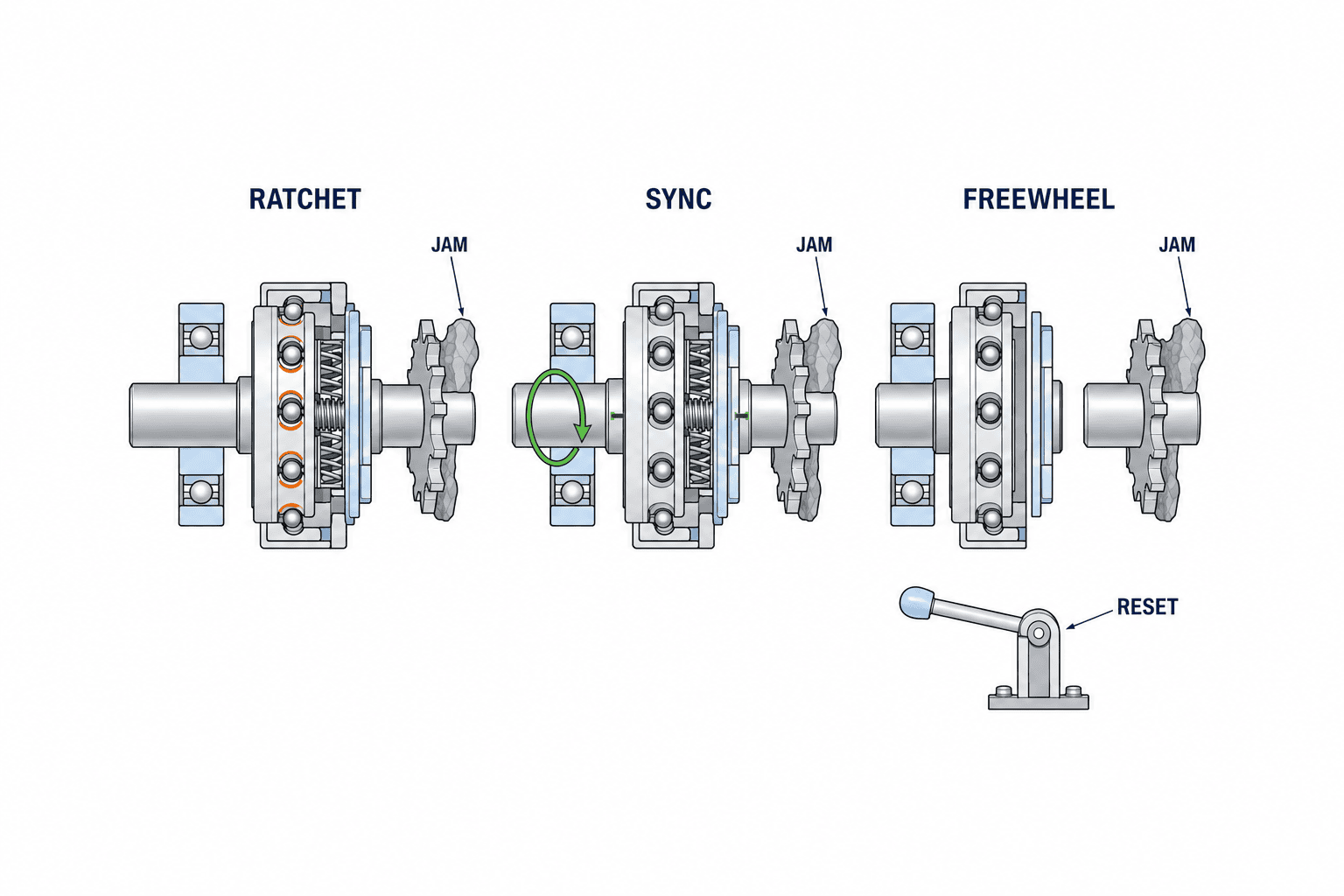
Load-separating torque limiters can ratchet and re-engage periodically, re-engage in a defined angular position, or remain disengaged until an operator or mechanism resets them. Mayr describes these variants for its EAS-compact family. Specific angles belong to a specific model: the EAS-compact product page lists 15-degree ratcheting and 360-degree synchronous re-engagement for the configurations shown. Do not copy those angles into another product’s specification without its own datasheet.
A ratcheting mechanism may reduce intervention where a brief release and return is acceptable. If the obstruction remains, however, the unit can repeatedly release and re-engage. KTR cautions that prolonged slipping or ratcheting increases wear and that high release torque in an automatically re-engaging design calls for reduced speed. A PLC stop command does not instantly remove the drive train’s kinetic energy; the number of possible re-engagements before rest matters.
A synchronous mechanism returns the relative angular position at a defined point. That can be useful for an indexed package cutter or an axis where phase matters. It does not prove that continued rotation during a jam is acceptable. A freewheel or completely disengaging design keeps input and output separated until reset. KTR recommends an idle-rotation version for drives with large mass inertia or higher speed to reduce the wear associated with automatic re-engagement. The tradeoff is the need for reset access, a defined inspection and more downtime.
| Method | Typical post-release behaviour | Main design question |
|---|---|---|
| Friction or load-holding | Slips while some torque remains transmitted | How much heat, wear and position error are acceptable? |
| Ratcheting | Re-engages at intervals after load falls | What happens if the jam remains? |
| Synchronous | Re-engages at a defined phase | Is continued rotation safe for the workpiece? |
| Complete separation or freewheel | Stays disconnected until reset | Who inspects and how is it reset safely? |
The table is a comparison of operating principles, not an approval of any model. Speed, torque, allowed slip time, repeatability and reversing behaviour must be verified for the exact ordered configuration.
Link mechanical release detection to machine control
A mechanically released limiter does not automatically stop the motor. Mayr offers mechanical and contactless switches that detect limiter movement or end positions. KTR recommends electrical monitoring so the drive can be shut down promptly after overload. Include the sensor, target movement, bracket, wiring, PLC input, diagnostic logic and motor stop sequence in the same specification as the clutch.
An alarm on a screen is not enough. Define whether the motor is stopped, a brake is applied, upstream feed is inhibited, workpieces are held, an event is logged and maintenance is called. Consider a broken sensor cable or a switch that never changes state. Test the control response to a simulated release signal, and where safely possible test the actual sensor movement. A fault should not be silently interpreted as permission for automatic restart.
Distinguish product-protection detection from a safety-rated personnel protection function. A limiter switch does not automatically replace a guard interlock. A person clearing a jam may face stored motion, gravity, compressed air or unexpected motor restart even when torque transmission has been interrupted. OSHA’s 29 CFR 1910.147 explains principles for isolating and verifying hazardous energy during service work; citing it here does not claim that US law applies in Thailand. Apply local requirements and the site’s approved safety procedure. Machine-safety guidance from Pilz likewise emphasizes preventing unexpected restart after access to a hazardous area.
Resetting the limiter and authorizing a machine restart are separate decisions. Before restart, remove the cause of overload, inspect the shaft and tooling, locate displaced workpieces, restore guards and document the incident. Even with automatic mechanical re-engagement, control logic should permit motor restart only under defined conditions.
Check fit, environment and maintenance before approving a model
Confirm bore, keyway, clamping method, flange, shaft support, alignment, axial clearance, guard distance and inspection access against the actual machine drawing. A flange-mounted sprocket or pulley may impose radial loads; ask the manufacturer whether the unit’s bearing arrangement supports them or an external bearing is required. KTR presents flange styles for sprockets and pulleys, but the correct arrangement remains application specific.
List ambient temperature, washdown, dust, corrosion, lubricant, humidity and the enclosure condition. A cover can trap heat; a washdown can affect a sensor connector. Service life depends partly on the number and duration of overloads. Request inspection intervals, wear limits, reset tools and spare-part numbers. If an old machine needs a shaft removed to change the limiter, that work and its outage belong in the comparison of offers.
Published maximum torque, bore and speed are limits for a defined configuration, not permission to run every parameter at its maximum simultaneously. Ask the manufacturer to confirm the combined duty and the final drawing. Measure the installed machine before approving machining or a replacement hub.
RFP checklist for a comparable torque-limiter quotation
A request for “a torque limiter around 100 Nm” invites incompatible offers. KTR advises providing as much drive information as possible to improve selection. Include a power-path diagram, exact shaft location, speed and torque profile, acceleration time, inertia referred to that shaft, fault scenario, protected-component limit, preferred release behaviour and stopping sequence.
Specify the supply boundary. One supplier may quote only the limiter while another includes the hub, flange, sensor, bracket, wiring, setup, spare parts and FAT/SAT. The total installed cost also includes shaft modification, guarding, control wiring, production downtime and the recovery time after a real trip.
| RFP field | Requested information |
|---|---|
| Machine and objective | Line, process, protected part and credible jam |
| Drive train | Motor, reducer, brake, shaft location and rotation directions |
| Load | Steady, start, acceleration and reverse torque, with measurement method |
| Inertia | Driving and driven inertia referred to the specified shaft |
| Setting window | Normal peak, damage limit, desired setting and uncertainty |
| Release and reset | Ratchet, synchronous or disengaging action; stop and restart logic |
| Installation | Bore, key, flange, supports, alignment and available space |
| Environment | Speed, temperature, dust, washdown and guarding |
| Scope | Switch, bracket, cable, spares, manual, setting record |
| Acceptance | FAT/SAT plan, training and handover documents |
Mark missing measured values as “not yet measured” rather than turning assumptions into facts. Ask suppliers to return their assumptions, calculations, limitations and an alternative when the requested setting window is impossible. If two quotes use different load assumptions, reconcile them before comparing prices.
Separate FAT evidence from SAT evidence
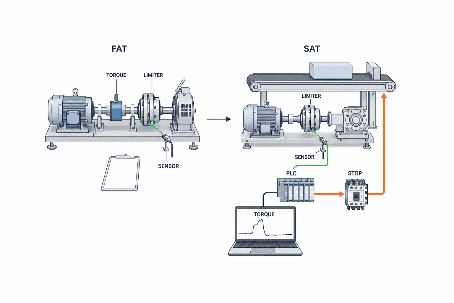
FAT covers what can be checked before shipment: ordered model, hub dimensions, preset torque, locking or witness marking, release and reset mechanism, switch output, manuals and included spares. A controlled test rig may demonstrate release at an agreed torque, if the supplier and buyer define a safe method and acceptable range. Destroying a production machine by forcing a real jam is not an acceptance requirement.
SAT evaluates the installed system: real startup and full-load peaks, nuisance release, detection through the PLC, time to stop, workpiece movement, guards, reset procedure and records. A simulated overload input can check stop logic separately from a safe mechanical test. The plan must account for residual rotation and avoid hazardous deliberate jams. A successful bench test cannot establish that the actual conveyor will stop before its workpiece reaches a fixed obstacle.
Record the test condition, instrument, as-set torque, measured response, speed at release, PLC event, final stop time, reset action and signoff. Agree pass limits based on the component specifications and machine design. “The clutch released” alone is not an adequate pass criterion. If the setting is changed during SAT, update drawings, maintenance records and the spare-part specification.
Common failure patterns and practical controls
One common error is multiplying motor nameplate torque by a fixed factor and discovering that normal acceleration trips the limiter. Measure or justify the peak on the actual protected shaft. Another is assuming mechanical separation also stops the motor. Test the electrical detection and stopping sequence, including coasting and possible re-engagement. A third is raising the setting after a nuisance trip without checking the protected part’s allowable torque. Require change control and a documented re-test.
A fourth error is leaving reset out of the maintenance procedure. Repeatedly re-engaging a unit without clearing the jam invites a repeat fault. Assign responsibility for energy isolation, jam removal, inspection, setting verification and restart authorization. At a multilingual Thai site, use consistent terms for “release,” “stop,” “reset” and “restart” on the panel and in work instructions. Finally, stock any wear part, sensor or tool needed to recover from a trip. Recurrent trips should prompt investigation of feed, product variation and detection timing rather than simply a stronger clutch.
Validate the protection sequence against specific failure modes
“The limiter will release first when anything jams” is not a sufficient design argument. Where the force enters the mechanism changes which component takes the first load. A fixture striking an obstacle may put bending force into a support or bearing before the torque at the limiter reaches its setting. Trace the force path on a mechanical drawing. For each credible failure mode, note the cause, first moving or loaded part, available detection signal, motion remaining before stop and recovery task. A limiter that restricts transmitted rotary torque cannot automatically protect against every local bending load, loss of position or gravity-driven movement.
Different protected components may imply incompatible settings. A low value might save the gearbox, while a legitimate product cycle needs a higher value. Before compromising with an arbitrary setting, compare longer acceleration, reduced friction, a redesigned guide, stronger weak component or a mounting location closer to the load. Also split the stopping sequence into release detection, PLC processing, drive torque reduction, brake action and coast-down. FAT can measure parts of the panel logic; SAT must include the installed machine’s inertia. Separate measurements show whether an apparent late stop is caused by the clutch, sensor, control or mechanics.
Control setting changes during commissioning and operation
A nuisance release during commissioning is a reason to investigate, not automatically to increase the setting. Locate the event in the acceleration or feed cycle and review workpiece dimensions, conveyor resistance, bearings, belt tension, lubrication and alignment. Correct an abnormal mechanical load before changing the protection threshold. If a legitimate product change increases the normal peak, compare it again with the protected component’s limit.
A change record should show the old and new settings, reason, before-and-after torque traces, normal peak, damage limit, post-change release test and approver. Follow the model’s specified adjustment and verification method; a scale mark may not be a calibrated measurement of actual release torque. Where a cover must be opened, include hazardous-energy isolation and a check that guarding is restored. In production, log the time, product, speed, motor current or torque trace, sensor event, stop duration, reset work and any damage. A trend in releases can then be traced to wear, altered process conditions, workpiece tolerance or a setting change.
A spare that looks identical can have a different re-engagement method. Label spares and equipment records with exact model, setting range, bore, switch option, rotation direction and reset procedure. After replacement, recheck alignment, fasteners, sensor gap, setting and stop signal; observe the initial run at reduced speed. Stock alone does not guarantee a short recovery without an installation and acceptance checklist.
Let the process determine the behaviour after overload
An indexed packaging axis may depend on re-engagement phase, but continued rotation through trapped film can tear the material. A conveyor may need the load side to stay still until a jam is cleared; freewheeling with electrical stop detection may suit that case. A screw feeder or mixer can have large legitimate torque variation with material viscosity, narrowing the setting window. Investigate material and startup conditions before simply selecting a larger unit.
On a multi-product line, adjusting a mechanical limiter for every recipe increases the chance of a wrong setting. Determine whether one common setting works; if not, revisit tooling, drive configuration or process conditions. Software monitoring for different recipes can complement the mechanical device, but the response sequence must be tested. A recipe change does not change the strength of the protected part. For internationally supplied equipment in Thailand, align torque units, motor-side versus reducer-output values, and rpm versus cycle rate in quotations and test sheets. Define whether “reset” means mechanical re-engagement, clearing a PLC alarm or authorizing production restart; those are different actions.
Torque limiter selection FAQ
How many times motor-rated torque should the setting be?
There is no universal multiplier. Find a setting above legitimate peaks and below the protected component’s damage limit, allowing for unit tolerance and dynamic behaviour. KTR’s 30% margin above maximum operating torque is manufacturer guidance for the cited KTR-SI selection, not proof that a particular machine is protected. Validate the complete window with the supplier.
Will an automatic-reset overload clutch always reduce downtime?
It may when repeated engagement cannot damage the work or equipment. A jam that persists can cause repeated releases and wear. Compare a freewheel or complete-disengagement option for large inertia or high speed. Mechanical re-engagement does not mean the motor may automatically restart.
Can a servo torque limit and a mechanical limiter be used together?
Yes, if their respective fault scenarios and sequence are defined. Drive software limits, mechanical release and safety functions respond to different conditions and are not interchangeable. Review power loss, control faults and impact loading separately in the machine risk assessment.
What is the difference between FAT and SAT for a torque limiter?
FAT verifies the ordered component, setting, dimensions, mechanism, detection and documents under supplier-controlled conditions. SAT verifies real operating peaks, stop sequence, workpiece effects and reset at the installed machine. Use safe simulation where a real jam would be dangerous.
Is it safe to clear the jam immediately after release?
No assumption of zero energy is justified. Motor motion, braking, gravity, pressure or inertia can remain. Follow the site’s isolation, stored-energy control and verification procedure before entering the hazardous area.
Conclusion
Choose a torque limiter by defining a usable window between normal process peaks and the protected component’s limit. Then specify the physical behaviour after release, detection, stop logic and deliberate reset. Supply the drive data in the RFP, verify the delivered unit in FAT and the integrated machine in SAT, and retain setting records for the next overload event.
If your team is evaluating a limiter on a Thai conveyor or automated machine, contact TOMAS TECH while the drawings or torque measurements are still being assembled. We can help frame the load data, supplier scope and acceptance conditions for a practical comparison.


