


Production engineering and maintenance staff at Japanese-owned plants in Thailand often bring us questions about proximity sensor selection, and they usually start like this: “We mounted it at the catalog sensing distance, but it does not react to the aluminium workpiece.” “We fitted the NPN sensor we were used to in Japan to the PNP input of a European-built machine.” “Since we switched to a 2-wire type, the output will not turn off.”
The argument of this article is as follows. Proximity sensor selection is not decided by “the catalog sensing distance” but by “a safe-side distance corrected for the material, size and mounting conditions of the actual workpiece.” Correction factors, response frequency and mutual interference values differ by manufacturer and by model, and every one of them is a value tied to measurement conditions. That is why you check them in the datasheet of the model you adopt, have the supplier write the basis into the RFP (request for proposal), and confirm with actual workpieces in the acceptance tests (FAT/SAT). Specifically, there are seven points.
- The catalog sensing distance is the value for a 1 mm thick iron plate (the standard sensing object). Omron defines the “set distance” that can be used stably as about 70–80% of the rated sensing distance, while European datasheets use a different notation, the “assured operating distance Sa.”
- Material shrinks the sensing distance considerably. Calculating with the values of a single Contrinex product, copper gives only about 18% of the distance obtained with steel. On top of that, the factors differ by manufacturer; in this article’s calculation, the guideline value for stainless steel splits into 4.48 mm and 5.44 mm.
- Shielded and unshielded types differ in both sensing distance and how much attention surrounding metal needs. If you mount sensors side by side, you also need spacing to avoid mutual interference.
- Response frequency is a catalog value tied to measurement conditions. When comparing it with the number of detections you need, take the difference in conditions into account.
- Match the output type to the PLC input unit. For DC 2-wire types check leakage current and residual voltage; for 3-wire types check NPN/PNP compatibility.
- Environmental and mounting conditions such as IP rating, cutting oil, welding, noise, tightening torque and cables determine service life and malfunctions.
- Turn all of the above into RFP items, and confirm them in FAT/SAT with actual workpieces and actual mounting.
Note that this article is not a recommendation or ranking of specific products. Product functions and performance are “manufacturer descriptions and claims” based on the manufacturers’ published materials, and numbers are given with the company name and series. The model calculations in the second half are hypothetical numbers used for explanation and are not data from real equipment. Prices and monetary amounts are not covered.
What Is a Proximity Sensor: Inductive, Capacitive and Magnetic Types
A proximity sensor detects whether an object is “nearby” without touching it. Omron’s technical guide divides detection principles into three: a method that uses eddy currents generated in a metal sensing object by electromagnetic induction (inductive), a method that uses changes in capacitance (capacitive), and a method that uses a magnet and a reed switch (magnetic). Keyence also broadly classifies them into three: “high-frequency oscillation type (electromagnetic induction),” “magnetic type” and “capacitive type.”
Omron explains that JIS C 8201-5-2 defines proximity sensors and that this definition is consistent with the definition in IEC 60947-5-2.
| Type | Detection principle (manufacturer description) | What it can detect | What to watch around it |
|---|---|---|---|
| Inductive | An AC magnetic field from a coil induces eddy currents in metal, and the change in impedance or the attenuation of oscillation is detected (Omron, Keyence) | Metals (iron, aluminium, brass, copper, etc.) | Surrounding metal |
| Capacitive | Detects changes in capacitance between the sensing object and the sensor (Omron) | Metals plus resin, liquids, powders, etc., depending on permittivity | Any surrounding object |
| Magnetic | Magnet and reed switch (Omron) | Magnets | — |
On choosing the principle, the Pepperl+Fuchs (hereafter P+F) general catalog recommends inductive types for metal targets, capacitive types for plastics, paper, liquids, granules and powders, and magnetic types for targets containing magnets. Most applications that confirm workpiece presence or clamp position in jigs and automated machines deal with metal, so this article focuses on inductive types. How to proceed with designing and building the jig itself is covered in our article on jig design and manufacturing.
There are also variants within the inductive type. Omron lists a type that detects aluminium (detecting the phase component of the frequency), an all-metal type, and a pulse-response type (generating eddy currents with pulses and detecting their change over time). For its non-ferrous metal type, Keyence explains that it uses the property that the oscillation frequency rises when aluminium or copper approaches and falls with ferrous metals, and notes that SUS304 has intermediate properties.
As features of proximity sensors, Omron lists that they do not wear because they are non-contact, have a long life because they have no contacts (magnetic types excluded), can be used where water or oil is present, are hardly affected by color, and respond quickly. On the other hand, it also states that they are affected by ambient temperature, surrounding objects and other sensors. Proximity sensor selection is the work of eliminating these “affected by” conditions one by one.
Sensing Distance Terms: Rated Sensing Distance, Set Distance, Sn/Sr/Sa and the Standard Sensing Object
The first thing to pin down in proximity sensor selection is what the catalog “sensing distance” actually means. Let us sort out the manufacturers’ terminology.
Omron’s terms
Omron’s technical guide defines them as follows.
| Term | Omron’s definition |
|---|---|
| Standard sensing object | A sensing object with specified material, shape and dimensions, used as the reference for measuring basic performance |
| Sensing distance | The distance from the reference surface at which the sensor operates (resets) when the standard sensing object is moved in the specified way |
| Set distance | The distance from the reference surface at which the sensor can be used stably, including the effects of temperature and voltage. About 70–80% of the rated sensing distance |
| Differential travel | The difference between the operating distance and the reset distance |
As a mounting precaution, Omron recommends mounting based on the set distance, because the sensing distance changes with temperature and voltage.
Looking at the specifications of the Omron E2E NEXT (DC 3-wire) as a real example, even among M18 shielded models the distance and the size of the standard sensing object differ by series.
| E2E NEXT series (shielded, M18) | Model | Sensing distance | Set distance | Standard sensing object (iron) | Response frequency (average) |
|---|---|---|---|---|---|
| BASIC Single distance | E2E-X5□18 | 5 mm ±10% | 0 to 4 mm | 18×18×1 mm | 600 Hz |
| BASIC Double distance | E2E-X8□18 | 8 mm ±10% | 0 to 6.4 mm | 24×24×1 mm | 500 Hz |
| PREMIUM Triple distance | E2E-X12□18 | 12 mm ±10% | 0 to 9.6 mm | 36×36×1 mm | 500 Hz |
| PREMIUM Quadruple distance | E2E-X14□18 | 14 mm ±10% | 0 to 10.6 mm | 42×42×1 mm | 350 Hz |
Dividing the set distance by the sensing distance gives 80.0% for both BASIC models (4÷5 and 6.4÷8), 80.0% for PREMIUM Triple (9.6÷12), and about 75.7% for PREMIUM Quadruple (10.6÷14). All fall within Omron’s definition of “about 70–80%.” Note that the longer the sensing distance of a series, the larger its standard sensing object.
How European datasheets write it (Sn, Sr, Sa)
European manufacturers’ materials use the symbols Sn, Sr, Su and Sa. The 2012 edition of the P+F general catalog explains them as the definitions of EN 60947-5-2 as follows.
- Rated operating distance sn: the “nominal” value that does not take into account manufacturing tolerances or external influences such as voltage and temperature
- Real operating distance sr: the value of an individual sensor measured at an ambient temperature of 23±5°C under specified voltage and mounting conditions
- Usable operating distance su: the value measured under conditions with extended temperature and voltage ranges
- Assured operating distance sa: the distance at which operation is assured under specified conditions
The Contrinex datasheet (DW-Ax-50x-065) also states “0.9Sn ≤ Sr ≤ 1.1Sn” and “Sa ≤ (0.81 x Sn),” and notes that the data follow IEC 60947-5-2 and were measured with a supply of 20–30 VDC at an ambient temperature of 23°C±5°C.
The point to be careful about here is the relationship with the standard’s text. The 4th edition (Ed. 4.0) of IEC 60947-5-2 was published on 18 October 2019, and the IEC catalog page lists changes to the specifications on sensing range and operating distance as one of the revisions. Because this article has not checked the text of the standard, the relationship between the symbols and numbers above is treated as “what the P+F and Contrinex materials explain.”
Omron’s set distance and the European Sa differ both in name and in the source of their definitions. Do not read one as the other. What they have in common is a single point: do not design at the position of the rated sensing distance (Sn) as is.
Also, this Contrinex product is specified so that its LED lights steadily when the sensing object is within 0.8 times the real operating distance, and flashes when it is beyond 0.8 times but within the real operating distance. The design signals by flashing that the object is in a region with little margin, which can be used for distance adjustment during commissioning.
Size of the standard sensing object: the P+F rule and Omron’s values match
The P+F catalog explains that the standard measuring plate is a square steel plate 1 mm thick, with a side length equal to the larger of “the diameter of the circle inscribed in the sensing face” and “3×sn.” Let us apply this to the Omron E2E NEXT BASIC Double distance shielded models (approximating the inscribed circle diameter by the M thread diameter is this article’s assumption).
| Model (Omron) | Thread size | Sensing distance | 3×sensing distance | Larger value | Omron standard sensing object |
|---|---|---|---|---|---|
| E2E-X2□8 | M8 | 2 mm | 6 mm | 8 mm | 8×8×1 mm |
| E2E-X4□12 | M12 | 4 mm | 12 mm | 12 mm | 12×12×1 mm |
| E2E-X8□18 | M18 | 8 mm | 24 mm | 24 mm | 24×24×1 mm |
| E2E-X15□30 | M30 | 15 mm | 45 mm | 45 mm | 45×45×1 mm |
All four models matched. In other words, the catalog sensing distance is the value for an iron plate of this size and 1 mm thick. For an M18, 8 mm model it is a 24 mm square iron plate. For workpieces smaller than this, such as bolt heads or thin pawls, the sensing distance becomes shorter (Omron, P+F). P+F explains that the operating distance increases only slightly for larger objects but drops considerably for smaller ones, and recommends verifying the operating distance when the object differs in size from the standard measuring plate.
Shielded vs Unshielded Proximity Sensors and the Effect of Surrounding Metal
Proximity sensors come in shielded (flush-mount) and unshielded types.
By Omron’s definition, in the shielded type the magnetic flux is concentrated in front of the sensor and the sides of the coil are covered with metal, so it can be embedded in metal. In the unshielded type the magnetic flux spreads widely in front and the sides of the coil are not covered with metal, so it is more easily affected by surrounding metal. Keyence similarly explains that shielded types can be embedded in metal (the EM series being an exception), and that unshielded types have a longer sensing distance but require attention to mounting position.
| Item | Shielded | Unshielded |
|---|---|---|
| Construction | Coil sides covered with metal, flux concentrated forward (Omron) | Sides not covered, flux spreads forward (Omron) |
| Mounting | Can be embedded in metal | Needs free space around it. Check dimensions in each datasheet |
| Sensing distance | Short | Long |
| Example distances (Omron E2E NEXT BASIC Double distance) | M12: 4 mm, M18: 8 mm | M12: 8 mm, M18: 16 mm |
The P+F catalog explains that flush-mount types need no free space around them and offer better mechanical protection and noise immunity, while for its own products the operating distance is about 60% of that of non-flush types. This is a description of P+F products. In the same-size comparison for the Omron E2E NEXT, the shielded distance is 50% of the unshielded one (8 mm vs 16 mm). The ratio also differs by manufacturer and product, so rather than memorizing it as a general value, compare the candidate models against each other.
For non-flush types, P+F illustrates that free space should be provided around the sensor to avoid the influence of surrounding metal. The specific dimensions need to be checked in each sensor’s technical data.
What surrounding metal causes
Omron’s precautions state that when metal other than the sensing object is near the sensing face, effects such as an apparent increase in operating distance, poorer temperature characteristics and failure to reset can occur. In particular, the distance to a metal surface facing the sensing face affects things such as shortening of the sensing distance.
Omron publishes tables of surrounding-metal dimensions for each model in its catalogs, and states that those values apply when the supplied nuts are used, and that changing the nut material changes the influence of surrounding metal. Even small changes, such as switching a jig bracket from iron to another material or replacing the nut with one from stock, can change the detection state.
For capacitive types, according to Omron, you need to watch the influence of “any object” around the sensor. That includes not only metal jigs but also resin covers, wiring and operators’ hands.
Proximity Sensor Selection Step by Step
Building on the terms so far, we have organized proximity sensor selection into eight steps.
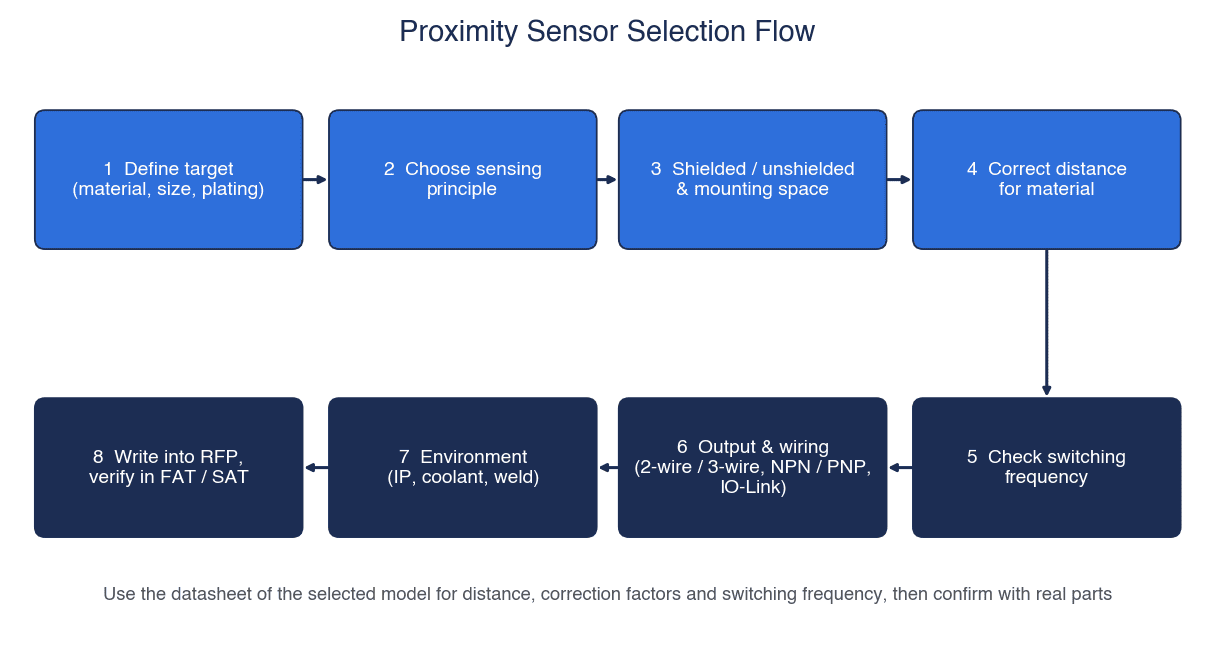
As the figure shows, the order is: (1) define the sensing object (material, size, plating), (2) choose the sensing principle, (3) decide shielded or unshielded together with the mounting space, (4) correct the distance for material, (5) check the response frequency, (6) decide output and wiring (2-wire/3-wire, NPN/PNP, IO-Link), (7) check the environment (IP, cutting oil, welding), and (8) write it into the RFP and confirm it in FAT/SAT.
There is a reason for this order. The distance cannot be calculated until “what to detect” is decided, and the output type cannot be chosen until the PLC input unit is decided. Conversely, if you fix the model first and adapt material and wiring afterwards, you get rework such as “it does not react to aluminium” or “we fitted NPN to a PNP input.”
The table summarizes what to check at each step.
| Step | What to check | Main sources |
|---|---|---|
| 1 Sensing object | Material, presence and thickness of plating, plate thickness, size (compared with the standard sensing object), approach direction (head-on or from the side) | Omron, P+F |
| 2 Sensing principle | Inductive for metal, capacitive for resin, liquids and powders, magnetic for magnets | P+F, Omron |
| 3 Mounting | Shielded/unshielded, surrounding metal, facing metal, spacing to the adjacent sensor | Omron, P+F |
| 4 Distance correction | Based on the set distance or Sa, correct for material using the factors and characteristic charts in the adopted model’s datasheet | Omron, P+F, Contrinex |
| 5 Response | Required number of detections (Hz) versus the catalog response frequency and its measurement conditions | Omron, P+F |
| 6 Output | Leakage current and residual voltage for 2-wire, NPN/PNP for 3-wire, NO/NC, IO-Link supported types | Omron, P+F |
| 7 Environment | IP rating (including the standard name), cutting oil, weld spatter and magnetic fields, noise, cables | Omron, P+F, Balluff, ifm |
| 8 RFP and testing | Have the above basis submitted in writing, and confirm with actual workpieces | — |
When the sensing object enters from the side, the operating distance differs from the axial direction. P+F explains this as response curves according to axial offset, and Omron as diagrams of “sensing distance and sensing area in the horizontal direction.” For workpieces passing from the side, as on a conveyor line, decide the mounting position by looking at these diagrams.
Inductive Proximity Sensor Sensing Distance: Correcting for Material
With inductive proximity sensors, the sensing distance changes greatly with the material of the sensing object. Omron’s precautions state that the sensing distance varies greatly with the material of the sensing object and is generally shorter for non-magnetic metals such as aluminium.
The effect of material is expressed by a “correction factor.” In ifm’s explanation, the sensing distance for a given material = correction factor × nominal sensing distance. The Contrinex datasheet also writes the operating distance for aluminium as “Sn × CFAl.”
Here, using only the factors listed in the datasheet of the Contrinex DW-Ax-50x-065 (Ø6.5, rated operating distance Sn = 3 mm), let us calculate the distance for each material.

The figure above is a model calculation: the Sn of 3 mm of the Contrinex DW-Ax-50x-065 multiplied by the correction factors in the company’s datasheet (Sn×CF). Against 3.00 mm for steel, the distance drops to 2.01 mm for stainless steel (V2A), 1.05 mm for brass, 0.78 mm for aluminium and 0.54 mm for copper.
| Material | Contrinex correction factor | Sn×CF (mm) | Further ×0.81 (mm, this article’s assumption) |
|---|---|---|---|
| Steel (FE 360) | 1 | 3.00 | 2.43 |
| Stainless steel (V2A) | 0.67 | 2.01 | 1.63 |
| Brass | 0.35 | 1.05 | 0.85 |
| Aluminium | 0.26 | 0.78 | 0.63 |
| Copper | 0.18 | 0.54 | 0.44 |
The rightmost column is Sn×CF further multiplied by 0.81. The 0.81 borrows the ratio “Sa ≤ 0.81×Sn” from the same datasheet. However, Sa in the datasheet is a value for the standard sensing object (steel), and multiplying the material-corrected distance by 0.81 is this article’s assumption. Contrinex does not prescribe this calculation method.
Reading it is simple. Even with the same sensor, a copper workpiece gives only about 18% (0.54÷3.00) of the distance obtained with steel. Comparing in the rightmost column (×0.81), a positional relationship that allowed placement at 2.43 mm for steel would, by calculation, require bringing the sensor as close as 0.44 mm for copper before it detects. Considering workpiece variation and vibration, the margin becomes quite small. If you have many non-ferrous workpieces, this is grounds for considering the all-metal types (correction factor 1) or non-ferrous types explained later.
The Contrinex datasheet also states that for embedded mounting, the correction factor of the mounting base is multiplied in as well (Sn, Al = Sn×CFAl×CFemb, Al). Because the numerical mounting-base factors for this product could not be found in the datasheet, they are not included in the table above. Keep in mind that the distance can also change with mounting conditions.
Proximity Sensor Correction Factors Differ by Manufacturer: Comparing ifm and P+F Values
The factors in the previous section are those of a single Contrinex product. Placed side by side with other manufacturers’ published values, the values do not line up.
| Material | ifm standard sensors | P+F typical values (2012 catalog) | autosen | Contrinex DW-Ax-50x-065 |
|---|---|---|---|---|
| Steel (reference) | 1 | 1 | 1.00 | 1 |
| Stainless steel | 0.7 | 0.85 | 0.60–1.00 | 0.67 |
| Brass | 0.5 | 0.4 | 0.35–0.50 | 0.35 |
| Aluminium | 0.4 | 0.4 | 0.30–0.45 | 0.26 |
| Copper | 0.3 | 0.3 | 0.25–0.45 | 0.18 |
In its own catalog, P+F writes that correction factors are ratios relative to steel FE 360 (St37), that they differ by model depending on housing and shield materials, and that the values in each datasheet should be used. The manufacturer itself is saying “do not use this table as is.”
A model calculation shows how much this difference affects design. The premise is the Omron E2E-X8□18 (M18 shielded, sensing distance 8 mm, set distance 6.4 mm). However, the correction factors are not Omron’s; we hypothetically apply the published values of ifm and P+F (Omron’s material-specific characteristics were not obtained for this article).
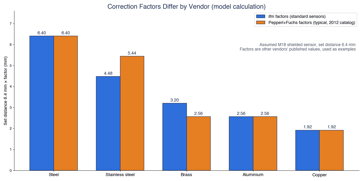
The figure above shows the set distance of 6.4 mm multiplied by the ifm and P+F factors respectively. Steel is 6.40 mm for both, stainless steel is 4.48 mm (ifm) and 5.44 mm (P+F), brass is 3.20 mm and 2.56 mm, and aluminium and copper are the same for both at 2.56 mm and 1.92 mm.
| Material | ifm factor | 8 mm×factor | 6.4 mm×factor | P+F factor | 8 mm×factor | 6.4 mm×factor |
|---|---|---|---|---|---|---|
| Steel | 1 | 8.00 | 6.40 | 1 | 8.00 | 6.40 |
| Stainless steel | 0.7 | 5.60 | 4.48 | 0.85 | 6.80 | 5.44 |
| Brass | 0.5 | 4.00 | 3.20 | 0.4 | 3.20 | 2.56 |
| Aluminium | 0.4 | 3.20 | 2.56 | 0.4 | 3.20 | 2.56 |
| Copper | 0.3 | 2.40 | 1.92 | 0.3 | 2.40 | 1.92 |
For stainless steel alone, the guideline set distance splits into 4.48 mm and 5.44 mm, a difference of 0.96 mm. For brass, conversely, ifm gives the longer value. Depending on which factor table you used, the mounting position shifts by close to 1 mm.
Stainless steel is also a material with large differences between grades. That autosen’s table gives stainless steel a range of 0.60–1.00, and that Keyence notes SUS304 as having properties between ferrous and non-ferrous metals, both show that it is hard to handle with a single factor.
The conclusion is do not design with a general factor table. Check with the factors or material-specific characteristic charts in the datasheet of the model you adopt, and if doubts remain, measure the distance with actual workpieces. Omron’s precautions page also does not give material factors as numbers, and instead directs readers to the engineering data (characteristic charts) in the catalog.
Thin, Small and Plated Workpieces, and Factor 1 / All-Metal Types
Besides material, the thickness, size and plating of the workpiece also change the sensing distance.
Thickness and size
According to Omron’s precautions, if the workpiece is smaller than the standard sensing object, the sensing distance generally becomes shorter. It recommends designing for objects at least as large as the standard sensing object, and taking ample margin if the object is the same size or smaller.
Regarding thickness, ferrous metals such as iron and nickel need a thickness of 1 mm or more. On the other hand, for non-magnetic metals, a sensing distance equivalent to that of magnetic materials can be obtained if the film (plating) thickness is 0.01 mm or less (pulse-response types such as the E2V have different characteristics). Extremely thin, non-conductive films such as vapor-deposited films cannot be detected.
Effect of plating
As “effect of plating (typical examples),” Omron gives reference values with the sensing distance without plating taken as 100.
| Plating type and thickness | Steel base material | Brass base material |
|---|---|---|
| No plating | 100 | 100 |
| Zn 5–15 μm | 90–120 | 95–105 |
| Cd 5–15 μm | 100–110 | 95–105 |
| Ag 5–15 μm | 60–90 | 85–100 |
| Cu 10–20 μm | 70–95 | 95–105 |
| Cu 5–15 μm | — | 95–105 |
| Cu (5–10 μm) + Ni (10–20 μm) | 70–95 | — |
| Cu (5–10 μm) + Ni (10 μm) + Cr (0.3 μm) | 75–95 | — |
There are examples where silver plating (Ag) on steel brings the sensing distance down to 60–90% of the unplated value. This means detection can become unstable on parts whose plating specification was changed later for appearance. The surface treatment field on the drawing is also an input to sensor selection.
Factor 1 (correction factor 1) / all-metal types
When you have many non-ferrous workpieces, or a mix of ferrous and non-ferrous, an option is a sensor whose distance varies little with material (correction factor 1). Here are the product families of each company alongside the manufacturers’ descriptions.
| Manufacturer and product family | Manufacturer’s description |
|---|---|
| ifm “Kplus” | One standardized sensing range for all metals. Factors for stainless steel, brass, aluminium and copper are all 1. Immunity to electromagnetic fields, Anti-spatter coating for welding, operating temperature -40 to 85°C, up to IP 68/IP 69K (all are ifm’s product claims) |
| P+F “Reduction factor 1” | Detects all metals at almost the same operating distance. Lineup with maximum operating distances from 2 to 75 mm, immunity to electromagnetic fields (as described in the 2012 catalog) |
| Balluff “Factor 1” BES05NC (M18) | Detects ferrous and non-ferrous metals at the same distance. Rated operating distance 8 mm with flush mounting, sensing face and housing in stainless steel 1.4404 (coated), PNP NO, 10–30 V DC, IP68 |
| Omron | “All-metal type” and “aluminium-sensing type” exist as categories of principle |
| Keyence | Aluminium-detection models (ED series; can also detect iron, check the characteristic charts) |
The same Balluff document also lists the BES05K8, which detects only ferrous metals, and the BES05K9, which detects only non-ferrous metals. Balluff cites mistake-proofing (poka-yoke) applications that confirm the material in assemblies where aluminium and steel are mixed. This is a way of using a proximity sensor to judge “whether a part of the correct material is fitted.”
Factor 1 also has weaknesses. The distributor autosen explains that, because of a construction using two air-core coils, a double pulse may be output when a small object passes from the side. If you use it in an application where small items pass across, this is a point to confirm with the actual parts beforehand.
Proximity Sensor Switching Frequency and Hysteresis: Compare with the Required Detections
In applications such as counting dogs on a rotating body or gear teeth, or counting workpieces flowing at high speed, the response frequency (switching frequency) matters.
Definition of response frequency and measurement conditions
Omron defines the response frequency as the number of detections that can be output per second when the standard sensing object is repeatedly brought close. According to the notes in the E2E NEXT specification table, the response frequency is an average value, measured with standard sensing objects lined up at “twice the width of the standard sensing object” as the interval, at a distance of 1/2 the sensing distance. P+F similarly shows a diagram in which measuring plates of side a are lined up at an interval of 2a and measured at a distance of Sn/2.
In other words, the catalog response frequency is the value when “standard-size objects pass at an interval of twice the object width, at half of Sn.” Under conditions where the actual dog is smaller, the interval is narrower, or the distance is greater, the catalog value may not be achieved.
Product values vary. In the Omron E2E NEXT (DC 3-wire), the response frequency tends to be lower the larger the size and the longer the sensing distance. The BASIC Double distance shielded types range from 1,500 Hz for M8 to 250 Hz for M30, and the unshielded M30 is 100 Hz. The Contrinex DW-Ax-50x-065 is 1,000 Hz or less.
Model calculation: how many Hz does rotation detection need?
Suppose 12 sensing dogs are mounted at equal intervals on a rotating disc that turns at 1,500 r/min (the number of dogs and the rotation speed are this article’s assumptions). The sensor is the Omron E2E-X8□18 (response frequency 500 Hz).
| Item | Calculation | Result |
|---|---|---|
| Required number of detections | 12 dogs × 1,500 r/min ÷ 60 | 300 Hz |
| Ratio to the catalog value | 300 Hz ÷ 500 Hz | 0.60 |
| Theoretical maximum rotation speed with the same sensor and 12 dogs | 500 Hz × 60 ÷ 12 dogs | 2,500 r/min |
As a cross-check, 1,500 r/min is 25 revolutions per second, and 25×12 = 300 Hz. At 2,500 r/min it is about 41.7 revolutions per second, and ×12 gives 500 Hz.
Here is also a conveyed-workpiece example. With a conveying speed of 60 m/min (1 m per second) and a workpiece pitch of 50 mm (both assumptions), the required number of detections is 1 ÷ 0.05 = 20 Hz, which is sufficiently low relative to the response frequency.
What we want you to note is do not judge feasibility from this comparison alone. The 500 Hz of the E2E-X8□18 is an average value when 24×24×1 mm standard sensing objects are lined up at twice the object width and passed at 1/2 the sensing distance. If the dog is smaller, the interval narrower or the distance greater, the conditions are different. Also, the manufacturer does not present the ratio of 0.60 as a criterion such as “pass if at or below this.” For applications that count rotation speed, consider whether a proximity sensor is appropriate in the first place together with our article on rotary encoder selection.
Hysteresis (differential travel)
Proximity sensors have differential travel, so the position at which the output turns ON differs from the position at which it turns OFF. This mechanism keeps the output from chattering even if the sensing object vibrates slightly at the stop position.
| Product | Differential travel |
|---|---|
| Omron E2E NEXT (most models) | 15% or less of the sensing distance |
| Omron E2E NEXT Single distance | 10% or less of the sensing distance |
| Contrinex DW-Ax-50x-065 | 3–15% of the real operating distance |
Because of the differential travel, there are limits for applications that judge position finely. Omron recommends using separate-amplifier types if high precision is needed. For applications that check “whether it stopped at the right position,” such as confirming the indexing position of a rotary index table, decide the dog shape and mounting position on the premise that the judgment will have a width equal to the differential travel.
Output Types: Leakage Current and Residual Voltage of DC 2-Wire Sensors
Among proximity sensor output types, the DC 2-wire type is the one with the most trouble.
How 2-wire types work
In a 2-wire type, the power lines double as the signal lines. In P+F’s explanation, a 2-wire type is connected in series with the load; a small leakage current flows even when OFF, and a small voltage drop occurs when ON. Omron cautions that wiring only the power lines may damage internal elements, so a load must always be included. Keyence explains that 2-wire types are easy to wire and can be used with both NPN and PNP circuits.
The specifications of the Omron E2E NEXT DC 2-wire (Standard model) are as follows.
| Item | Omron E2E NEXT DC 2-wire value |
|---|---|
| Leakage current | 0.8 mA or less |
| Residual voltage | Polarized 3 V or less, non-polarized 5 V or less (load current 100 mA, cable length 2 m) |
| Load current | 3–100 mA |
| Supply voltage | 12–24 VDC |
Leakage current keeps the load from turning OFF
Omron’s technical guide states that with 2-wire types, a current of up to 0.8 mA flows to the load even when the output is OFF, so you should confirm that the load does not operate on this current. The judgment formula is as follows (Omron’s precautions).
(Leakage current) × (load input impedance) < (load reset voltage)
As a model calculation, take the leakage current as 0.8 mA, the maximum value for the E2E NEXT DC 2-wire, and assume a load input impedance of 5.6 kΩ and a reset voltage of 5 V (these are not the specifications of a specific PLC).
| Item | Calculation | Result |
|---|---|---|
| Voltage on the load side due to leakage current | 0.8 mA × 5.6 kΩ | 4.48 V |
| Judgment | Compare 4.48 V with 5 V | 4.48 V < 5 V, so OFF by the formula |
| Margin | 5 V − 4.48 V | 0.52 V |
By the formula it turns OFF, but the margin is only 0.52 V. If the load input impedance were a little larger, the formula would no longer be satisfied. Omron writes that leakage current generally increases at higher voltages, and that care is needed when replacing limit switches or microswitches.
If the margin is insufficient, Omron recommends connecting a bleeder resistor in parallel with the load and designing so that the formula above is satisfied. The guidelines are 15 kΩ or less and 450 mW or more for 12 VDC, and 30 kΩ or less and 0.1 W or more for 24 VDC. Another approach is to choose a 3-wire type; P+F states that the leakage current of 3-wire types is negligible.
Residual voltage keeps the load from turning ON
Even when ON, a voltage remains inside the sensor. With a 24 V supply and a residual voltage of 3 V (the maximum for the E2E NEXT DC 2-wire, polarized), the voltage applied to the load is 24 − 3 = 21 V. The actual voltage distribution changes with load current and cable length, but if the operating voltage of a load such as a relay is higher than this, it will not turn ON. Omron also notes, in its connection example for relay loads, that attention should be paid to the 3 V residual voltage of DC 2-wire types.
For AC 2-wire types, Omron recommends inserting a bleeder resistor so that the sensor current is at least 10 mA (10 kΩ or less and 3 W (5 W) or more at 100 VAC, 20 kΩ or less and 10 W (20 W) or more at 200 VAC). If electronic devices that use AC half-wave rectification, such as timers, are used as the load, operation may also become unstable.
NPN vs PNP Proximity Sensor Wiring: 3-Wire Types, PLC Inputs and NO/NC
In 3-wire types, the power supply and load connections are separate. According to P+F, they have overload protection, short-circuit protection and reverse-polarity protection, and the leakage current is negligible. The Omron E2E NEXT 3-wire types also have power supply reverse-polarity protection, surge suppression, output short-circuit protection and output reverse-polarity protection.
Difference between NPN and PNP
In P+F’s explanation, PNP (switched high) is when the load is connected between the output and 0 V, and NPN (switched low) is when the load is connected between the output and +UB. If the sensor’s output type and the PLC input unit specification do not match, the input will not register.
| Item | NPN output | PNP output |
|---|---|---|
| Load connection (P+F) | Between output and +UB | Between output and 0 V |
| Output behavior (P+F) | switched low | switched high |
| Omron’s description | General-purpose transistor output that can be connected directly to PLCs and counters | Mainly built into machines for overseas markets such as Europe |
The only primary-source information we could confirm on regional usage is Omron’s description above. There is no material showing how widely NPN and PNP are used in Thai plants. In Japanese-owned plants in Thailand, equipment brought from Japan and European-built equipment sometimes stand on the same line, and the input unit specification can differ from machine to machine. The criterion is not “which is more common” but matching the PLC input unit of that particular machine. Manage spare-part model numbers per machine, and put a system in place so that NPN and PNP are not mixed up just because “it is the same M18.” The basics of PLC inputs are explained in our article on PLC basics.
NO and NC
By Omron’s definition, with NO the output is ON when an object is in the sensing area, and with NC the output is ON when there is no object. Some models allow switching between NO and NC. Decide which to use together with the logic of the PLC program and how abnormal conditions are handled.
Order of power-on and power-off
Omron cautions that because the sensor becomes able to detect within 100 ms after power-on, the design should turn on the sensor’s power first, and that because an output pulse may occur when power is turned off, the load-side power should be turned off first. P+F lists the time from power-on until the sensor is ready for use as a maximum of 300 ms (a value for P+F products). This time differs by manufacturer and product, so the time for which the PLC program ignores inputs right after power-on should be determined from the value of the adopted model.
Series (AND) and parallel (OR) connections are also possible, but Omron states that depending on the model a relay may be required, and that they may be unusable due to the effects of false pulses or leakage current.
What IO-Link Proximity Sensors Can Provide
With IO-Link-capable proximity sensors, in addition to the ON/OFF output, you can exchange sensor status and settings.
| Manufacturer and product | What can be handled via IO-Link (manufacturer’s description) |
|---|---|
| Omron E2E NEXT | IO-Link Ver 1.1, COM2 (38.4 kbps)/COM3 (230.4 kbps), minimum cycle time COM2 2.3 ms/COM3 0.4 ms. NO/NC switching, self-diagnosis, selection of the judgment distance for “too close,” timer, instability output, monitor output, readout of operating time, readout of sensor internal temperature, etc. |
| ifm inductive sensors | As cyclic data, the current damping value, switching output and device status. Teaching of the switch point, switching cycle counter, operating hours counter, power-on counter, locating the device by LED flashing, etc. |
| Contrinex DW-Ax-50x-065 | IO-Link 1.1, 7-bit process data, COM2 (38.4 kBaud), minimum cycle time 10.4 ms |
As application examples, ifm lists continuous distance monitoring, detection of chain elongation, shaft imbalance and material discrimination. Omron promotes that through an IO-Link master, the location and nature of a fault can be grasped quickly from the HMI, MTTR (mean time to repair) can be shortened, and condition monitoring helps predictive maintenance (manufacturer’s claim).
Watch for output type restrictions
An easily overlooked point is that some products support IO-Link only on certain output types. The Omron E2E NEXT specification table notes that the NC-type PNP outputs and all NPN outputs do not support IO-Link. For the Contrinex DW-Ax-50x-065 as well, as far as the model table shows, only the PNP NO type carries the IO-Link designation.
For this reason, introducing IO-Link into existing equipment that has been standardized on NPN may involve reviewing the output type. This cannot be said of every product, but it is an issue to check for the output types supported by the candidate models. How to think about extending IO-Link to safety devices is covered in our article on introducing IO-Link Safety.
Environment: IP Rating, Cutting Oil, Welding and Noise
IP rating and cutting oil
The Omron E2E NEXT specification table states the degree of protection of the pre-wired and pre-wired connector types as “IEC 60529: IP67, ISO 20653 (former standard DIN 40050 PART9): IP69K, JIS C 0920 Annex 1: IP67G,” and further states that they pass Omron’s own oil-resistant component evaluation standard (cutting oil as specified in JIS K 2241:2000, temperature 35°C or lower). IP67 and IP69K are notations based on different standards, so having the supplier write down the standard names in the RFP is the reliable approach.
Regarding cutting oil, Omron’s product page claims that a new PVC formulation prevents swelling, deterioration and cracking of the cable and keeps cutting oil out for up to 2 years. However, the note in the specification table makes clear that this “2 years” is the median (typical value) of product design and evaluation results, and that performance degradation is expected on average 2 years after shipment. It is a number to be read as a guide for replacement planning, not a guaranteed value. It is also stated that for pre-wired types, the protection rating is not satisfied at the portion where the cable sheath has been stripped. For processes with heavy cutting oil exposure, Omron points to its oil-resistant E2ER/E2ERZ.
According to the product page, Omron’s IP69K test conditions are a pressure of 8,000–10,000 kPa, hot water at 80°C, and 30 seconds at each angle. The P+F 2012 catalog lists IP65, IP67 and IP68 (EN 60529) depending on the product, a shock test of 30 G, 11 ms, and a vibration test of 10–55 Hz with 1 mm amplitude (IEC 60068-2-6).
Chip build-up is a separate issue
Omron writes that inductive types can detect with almost no influence from dirt, oil or water. On the other hand, it lists “adhesion and accumulation of metal powder” among its inspection items. Even if the sensor is robust against oil and water, metal chips that collect on the sensing face can themselves become a sensing object. Near machining processes, include inspection and cleaning intervals in the maintenance plan.
Welding environments: spatter and welding magnetic fields
Welding lines are a harsh environment for proximity sensors. Balluff explains that inductive sensors in welding environments tend to fail early due to impacts when workpieces are loaded and erosion from spatter.
| Manufacturer | Measures for welding environments (manufacturer’s description and claims) |
|---|---|
| P+F | Weld-immune sensors with immunity to strong magnetic fields and mechanical robustness. Sensing face of cross-linked PPS protects against spatter; housing of PTFE-coated brass |
| Balluff | Stainless steel sensing face (claimed to resist spatter burn-through and impact), improved coatings, immunity to welding magnetic fields through Factor 1, silicone weld-spatter-resistant cables |
| ifm | Anti-spatter coating for welding on Kplus. Claims that thanks to immunity to electromagnetic fields it does not malfunction even near electric brakes |
Balluff describes its Factor 1 products as “inherently weld-field immune,” but this is the manufacturer’s claim. Results can vary with welding current and distance conditions, so in welding cells, confirm under the actual welding conditions of the real machine. ifm’s magnetic sensors also have a function that allows an interference filter for welding areas to be enabled or disabled via IO-Link.
Noise countermeasures
Omron’s precautions list countermeasures for each type of noise.
| Type of noise | Countermeasures listed by Omron |
|---|---|
| Common-mode noise (inverter noise) | Ground the inverter motor (100 Ω or less). Ground the noise source and the 0 V side of the power supply via a capacitor (film capacitor 0.22 μF, 630 V). Insert insulation such as resin or rubber between the sensor and the metal mounting plate |
| Radiated noise | Insert a copper shield plate between the sensor and the noise source (such as a switching power supply), or increase the distance |
| Power line noise | Capacitors, noise filters (ferrite cores, isolation transformers) and varistors on the power line |
| Induction from wiring | Do not run in the same conduit or duct as high-voltage or power lines. Use a separate system, a dedicated metal conduit, or shielded cable |
| Surge | Near large surge sources such as motors and welders, insert a surge absorber on the surge source side |
It is also stated that an isolation transformer should be used for the DC power supply, and that an autotransformer should not be used.
Mounting: Threads and Tightening Torque, Cables and Mutual Interference
Tightening torque
Omron cautions that the catalog tightening torque should be observed so the sensor does not loosen from vibration, that excessive impact such as striking with a hammer during mounting should not be applied (risk of reduced water resistance or damage), and that a toothed washer is required for some models. The accessories of the E2E NEXT are a clamping nut and a toothed washer.
The permissible tightening torque varies greatly with the housing material. From the table in the P+F 2012 catalog, we extract the rows for which the column correspondence could be confirmed.
| Thread | Stainless steel | Brass | PBT | PPS |
|---|---|---|---|---|
| M18×1 | 30.0 N·m | 30.0 N·m | 1.5 N·m | 5 N·m |
| M30×1.5 | 30.0 N·m | 30.0 N·m | 3.0 N·m | 10 N·m |
Even for the same M18, the resin (PBT) housing is 1.5 N·m against 30 N·m for metal housings, a difference of more than an order of magnitude. Tightening a resin housing with the feel of a metal housing risks damage. For small-diameter unthreaded products, the Contrinex DW-Ax-50x-065 (Ø6.5) specifies a maximum tightening torque of 0.3 Nm when fixed with an M5 screw. Always use the value in each model’s datasheet, and write it into the assembly work standard as well.
Cables
From Omron’s precautions, here is how to handle cables.
- Built-in amplifier types can be extended up to 200 m with standard cable (some models are exceptions)
- Bending radius at least 3 times the cable outer diameter (at least 5 times for coaxial, shielded and robot cables)
- Tensile force 30 N or less for outer diameters under 4 mm, and 50 N or less for 4 mm or more. Do not apply tension to shielded or coaxial cables
- At 0°C or below, PVC cable becomes hard and may break if bent
- The insulated portion at the cable end is for Omron’s in-house inspection and is not covered by the warranty. Cut it off and terminate the cable before use
For cables routed along moving parts, include the bending radius and fixing method in the design drawings. On jigs where the sensor is mounted near moving parts, such as clamp confirmation on a toggle clamp, cable slack and clearance tend to be insufficient.
Mounting spacing for mutual interference
When proximity sensors are mounted side by side, the output may become unstable due to the AC magnetic field of the adjacent sensor. The P+F 2012 catalog gives a guideline for the center-to-center distance F when mounting side by side: at least 2 times the housing diameter for flush types, and at least 4 times for non-flush types. Applied to M18 (housing diameter 18 mm), this gives the following.
| Mounting M18 side by side (P+F guideline) | Calculation | Center-to-center distance |
|---|---|---|
| Flush type | 2 × 18 mm | 36 mm or more |
| Non-flush type | 4 × 18 mm | 72 mm or more |
This is a guideline for P+F products. For Omron products, follow the mutual interference table in each model’s catalog. Where the spacing cannot be secured, Omron cites alternating models with different oscillation frequencies, and P+F cites using products with offset oscillation frequencies (available on request).
Common Troubles and Countermeasures
Here are the causes and countermeasures described in manufacturers’ materials, organized by symptom.
| Symptom | Cause (manufacturer’s description) | Countermeasure and check | Source |
|---|---|---|---|
| Unstable output | Mutual interference between sensors mounted close together | Alternate models with different frequencies. If the frequency is the same, secure the minimum spacing | Omron, P+F |
| Apparent sensing distance increases / does not reset / changes with temperature | Surrounding metal, especially metal facing the sensing face | Follow the surrounding-metal table for each model. Note that changing the nut material changes the effect | Omron |
| Load does not turn OFF | Leakage current of 2-wire types | Satisfy the formula with a bleeder resistor, or switch to a 3-wire type | Omron |
| Load does not turn ON | Residual voltage of 2-wire types | Check the operating voltage of the load | Omron |
| Reduced water resistance or damage | Striking with a hammer, exceeding the permissible tightening torque | Observe the permissible tightening torque. Check whether a toothed washer is required | Omron |
| Unstable detection due to vibration | Environment with vibration and shock | Allow margin in the sensing distance and prevent loosening | Omron |
| Broken wire or poor contact | Bending cables at low temperature, excessive bending or tension | Observe the bending radius and tension limits | Omron |
| Malfunction | Induction from sharing a duct with power lines | Separate system, metal conduit, shielded cable | Omron |
| Early failure in welding cells | Impact when loading workpieces and erosion from spatter | Stainless steel sensing face, coatings, Factor 1 products (manufacturer’s proposal) | Balluff |
| Double pulse when small items pass across | Construction of Factor 1 (double coil) | Confirm beforehand in applications where small items pass across | autosen |
| Cable deterioration or oil ingress | Swelling, deterioration and cracking of cables due to cutting oil | Oil-resistant cable products and oil-resistant connector products | Omron |
As maintenance inspection items, Omron lists misalignment, loosening or deformation of the sensing object and sensor mounting, loose wiring, poor contact or broken wires, adhesion and accumulation of metal powder, and abnormalities in operating temperature or the surrounding environment.
Proximity sensor faults may appear not as breakdowns that stop equipment for a long time but as short stoppages. Stoppages such as the “workpiece present” signal dropping out for an instant and the sequence going into a wait state are hard to see in availability figures. How to record such stoppages and track their causes per machine is explained in our article on minor stoppage countermeasures. Rather than ending with a sensor replacement, recording which cause in the table above applies helps you avoid repeating the same stoppage.
Choosing Between Proximity Sensors and Photoelectric Sensors
A sensing component often used alongside proximity sensors is the photoelectric sensor. Here is how to think about choosing between them, based on the properties of proximity sensors covered in this article.
Inductive proximity sensors detect only metal and, according to Omron, are hardly affected by dirt, oil or water, and almost unaffected by color. Keyence also explains that because they detect only metal, they are not affected by adhering dust or oil. In exchange, as we have seen in this article, the sensing distance changes greatly with the material and size of the workpiece. The sensing distance itself is also short: in the specifications of the Omron E2E NEXT (DC 3-wire) cited in this article, it ranges from 1.5 mm for the M8 shielded type (BASIC Single distance) to 30 mm for the M30 unshielded type (BASIC Double distance).
| What to detect and conditions | Options to consider with proximity sensors | When to compare with something other than a proximity sensor |
|---|---|---|
| Iron workpieces, dogs, clamp parts | Inductive (standard products) | — |
| Aluminium, copper, brass, or mixed ferrous and non-ferrous | Inductive all-metal types, non-ferrous types, Factor 1 products | When the required distance does not fit within the corrected value |
| Resin, liquids, powders | Capacitive (watch the influence of any surrounding object) | When the distance or surrounding conditions of capacitive types do not fit |
| Objects containing magnets | Magnetic | — |
| Metal in places with oil, water or dirt | Inductive (Omron explains they are hardly affected; metal chips are a separate issue) | — |
When the sensing object is not metal, or you want to detect it from a position the proximity sensor’s sensing distance cannot reach, photoelectric sensors become the comparison target. How to choose a photoelectric sensor’s sensing mode and how to run acceptance tests are explained in our article on photoelectric sensor selection. Whether to use a proximity sensor or a photoelectric sensor is decided by the material of the sensing object, the distance to the detection position, and the surrounding environment (cutting oil, dust).
Automation Investment Trends in Thailand and Why Now
In Thailand, investment applications related to automation and robotics continue. All BOI figures are application amounts for investment promotion, not actual investment amounts or approved amounts.
| Indicator | Value | Scope and period | Source |
|---|---|---|---|
| BOI investment promotion applications (total) | About 1.47 trillion baht, 1,299 projects, +37% year on year | January–June 2026, application basis | BOI Press Release No.117/2569 |
| Of which machinery, automation and robotics sector | About 13.1 billion baht, 82 projects | Same as above | Same as above |
| Smart and Sustainable Industry measures (machinery upgrades, digitalization, automation/robot introduction) | 132 projects, about 17.2 billion baht | Same as above | Same as above |
| FDI applications from Japan | About 32.8 billion baht, 123 projects | Same as above | Same as above |
| BOI investment promotion applications (total) | 1.87 trillion baht, 3,370 projects | Full year 2025, application basis | BOI Press Release No.124/2569 |
| New industrial robot installations worldwide | 603,307 units (+11%) | Worldwide, 2025 | IFR World Robotics 2026 |
| New installations in Asia | 457,315 units (+14%, 76% of new installations worldwide) | Asia, 2025 | Same as above |
In its press release announcing results for full-year 2025 (No.124/2569), the BOI lists “Automation and Robotics” as one of its strategic sectors. According to the IFR, the operational stock of industrial robots worldwide in 2025 was 5,079,078 units (+9%), and new installations worldwide in 2026 are forecast at 655,000 units. The IFR Executive Summary does not give unit figures for Thailand alone.
Why review proximity sensor selection now
As robots and automated equipment increase, so does the number of points where proximity sensors are used, such as workpiece presence, home position and clamp confirmation. Yet proximity sensors are often left to the equipment maker as “standard parts,” and the plant side may be left with no record of the basis: on which material of workpiece, at what distance, and with which output type they were mounted. In plants where Japanese-made and European-made equipment are mixed, mix-ups between NPN and PNP, or between 2-wire and 3-wire, also occur. If you arrange to receive the basis for sensor selection in writing at the stage of writing the RFP for new equipment, investigating malfunctions after start-up and managing spare parts becomes easier.
Items to Write into the RFP
We have organized the items you should write into the RFP when ordering equipment or units that use proximity sensors. At the center is having the supplier submit in writing “for which workpiece, and with values under which conditions, the selection was made.”
| No. | Item | Example of what to write |
|---|---|---|
| 1 | Sensing object | Material, presence and thickness of plating, plate thickness, size (comparison with the standard sensing object), approach direction (axial/lateral) |
| 2 | Basis for design distance | Whether the set distance (Omron) or Sa (European datasheets) was used as the basis, rather than the rated sensing distance |
| 3 | Basis for material correction | Factors or characteristic charts in the adopted model’s datasheet, not a general factor table |
| 4 | Sensing principle | Inductive/capacitive/magnetic; whether all-metal, non-ferrous or Factor 1 types are adopted and why |
| 5 | Mounting conditions | Shielded/unshielded, dimensions for surrounding metal, facing metal and mutual interference (based on each model’s tables), permissible tightening torque |
| 6 | Response | Calculation of the required number of detections (Hz), and an explanation of the difference from the measurement conditions of the catalog response frequency |
| 7 | Output and wiring | For DC 2-wire, check of leakage current and residual voltage against the PLC input; for 3-wire, NPN/PNP compatibility with the input unit; NO/NC |
| 8 | IO-Link | If used, the supported output types and the data to be acquired (damping value, distance value, operating time, internal temperature, instability output, etc.) |
| 9 | Environment | IP rating (including the standard name), type of cutting oil and conditions of the oil-resistance evaluation, welding (spatter, magnetic fields), temperature range, noise sources |
| 10 | Power sequence | Time until detection is possible after power-on (value of the adopted model) and handling on the PLC side |
| 11 | Cables | Type (oil-resistant, for welding, etc.), bending radius, fixing method, whether connectors are used |
| 12 | Maintenance | Inspection items, list of spare-part models (down to the output type), supply and support within Thailand |
Item 3, “basis for material correction,” and item 5, “mounting conditions,” in particular differ in how much detail each equipment maker can provide. Writing them into the RFP from the start lets you compare them at the quotation stage.
Acceptance Test (FAT/SAT) Check Items
In the acceptance tests, confirm with actual workpieces and actual mounting not only that the sensor “reacted,” but that it reacts with margin. Decide the numerical pass/fail criteria based on the values in the adopted model’s datasheet and your own company standards, and write them into the RFP and test plan in advance.
| Check item | Test method | How to set the pass/fail criterion |
|---|---|---|
| Sensing distance with actual workpieces | Measure the operating and reset distances with workpieces of the actual material, plating and size | Corrected value from the datasheet and the margin your company has set |
| Mounting position margin | Record the difference between the mounting distance and the measured operating distance. For models that show margin by LED indication, also check that state | Margin your company has set |
| Lateral approach | If conveyed workpieces pass from the side, confirm detection at the actual passing position | Per specification |
| Response | At the actual rotation speed and conveying speed, check for missed detections by reconciling count values | Set by your company, e.g., zero missed detections |
| Surrounding metal and mutual interference | With all sensors mounted, confirm that the output does not become unstable due to adjacent sensors or brackets | No unstable output |
| Output and wiring | For 2-wire, whether the load reliably turns OFF when OFF and reliably turns ON when ON. For 3-wire, NPN/PNP compatibility with the input unit | Per specification |
| Power-on and power-off | Whether false inputs occur right after power-on and at power-off | Per specification |
| Tightening and wiring | Tightening torque, toothed washer, cable bending radius and fixing | Datasheet values |
| Environment | Run under actual operating conditions near cutting oil, welding and noise sources | No malfunctions |
FAT (factory acceptance test) is performed at the equipment maker’s factory, and SAT (site acceptance test) at your own plant in Thailand. Because workpiece lots, plating specifications, and the presence of nearby welders or inverters change on site, it is safer to repeat the checks for sensing distance and malfunctions in the SAT as well.
Frequently Asked Questions
What should I check first in proximity sensor selection?
The sensing object. Check the material (ferrous or non-ferrous, the grade of stainless steel), presence and thickness of plating, plate thickness and size. The catalog sensing distance is the value for a 1 mm thick iron plate (the standard sensing object), and the distance changes if the material and size differ, so you cannot choose a model until the sensing object is decided.
Can I use the proximity sensor sensing distance as stated in the catalog?
Not as is. Omron defines the “set distance,” which can be used stably including the effects of temperature and voltage, as about 70–80% of the rated sensing distance, and recommends mounting based on the set distance. European datasheets state the assured operating distance Sa. On top of that, correct for material, size and mounting conditions.
Can aluminium and stainless steel be detected?
They can be detected, but the distance becomes shorter. With the factors in the Contrinex DW-Ax-50x-065 datasheet, aluminium is 0.26 times and stainless steel (V2A) 0.67 times that of steel. Factors differ by manufacturer and model, so check them in the adopted model’s datasheet. If you have many non-ferrous workpieces, you can also consider all-metal or Factor 1 sensors.
What is the difference between shielded and unshielded types?
In the shielded type, the sides of the coil are covered with metal and it can be embedded in metal, but the sensing distance becomes shorter. The unshielded type has a longer distance but is more easily affected by surrounding metal and needs free space around it. For the Omron E2E NEXT M18, the shielded type is 8 mm and the unshielded type is 16 mm.
Should I choose a 2-wire or 3-wire type?
2-wire if wiring simplicity is the priority, 3-wire if margin on the load side is the priority. With 2-wire types, leakage current (0.8 mA or less for the Omron E2E NEXT DC 2-wire) flows even when OFF, and residual voltage remains even when ON, so they need to be checked against the PLC input and load specifications. P+F states that the leakage current of 3-wire types is negligible.
What is the difference between NPN and PNP? Which do Thai plants use?
In P+F’s explanation, NPN connects the load between the output and +UB, and PNP between the output and 0 V. Omron describes PNP output as mainly built into machines for overseas markets such as Europe. Since there is no material showing the ratio in Thai plants, choose according to the PLC input unit of each machine.
How much do proximity sensors cost?
Because it changes with the model, quantity, cable or connector, IO-Link support, and environmental specifications such as oil-resistant or welding types, this article does not cover monetary amounts. When comparing, fixing the sensing object, distance basis, output type and environmental conditions in the RFP before obtaining quotations lets you avoid the mistake of lining up and comparing quotations made under different conditions.
Summary
- Proximity sensor selection is decided not by the catalog sensing distance but by a safe-side distance corrected for the material, size and mounting conditions of the actual workpiece
- The catalog sensing distance is the value for a 1 mm thick iron plate (the standard sensing object). Omron uses the set distance (about 70–80% of the rated value), while European datasheets use a different notation, Sa. Do not treat them as the same thing
- Material shrinks the distance considerably. With the factors of a single Contrinex product, copper gives about 18% of steel. Factors differ by manufacturer, and the guideline for stainless steel splits into 4.48 mm and 5.44 mm with the ifm and P+F values (this article’s calculation)
- Do not design with a general factor table; check with the factors and characteristic charts in the adopted model’s datasheet. If you have many non-ferrous workpieces, all-metal and Factor 1 products are also candidates
- Shielded and unshielded types differ in distance and in how surrounding metal must be handled. If mounting side by side, secure spacing for mutual interference
- Response frequency is a value tied to measurement conditions. When comparing it with the required number of detections, take the difference in conditions into account and confirm with the actual parts
- For DC 2-wire, check leakage current and residual voltage against the PLC input and load. For 3-wire, match NPN/PNP to the input unit. For IO-Link, check the supported output types
- Write the IP rating including the standard name, and the conditions for cutting oil, welding, noise, tightening torque and cables into the RFP, and confirm them in FAT/SAT with actual workpieces and actual mounting
TOMAS TECH supports control design and electrical design of automated machines, jigs and conveying equipment for Japanese manufacturers in Thailand. You are welcome to consult us even at the stage of investigating the causes of sensor malfunctions on existing equipment, organizing sensor specifications, or preparing an RFP. Please feel free to reach us via our contact page.
References
- OMRON, Technical Guide: Proximity Sensors — Introduction: https://www.ia.omron.com/support/guide/41/introduction.html
- OMRON, Technical Guide: Proximity Sensors — Explanation of Terms: https://www.ia.omron.com/support/guide/41/explanation_of_terms.html
- OMRON, Technical Guide: Proximity Sensors — Further Information: https://www.ia.omron.com/support/guide/41/further_information.html
- OMRON, Safety Precautions for All Proximity Sensors: https://www.ia.omron.com/product/cautions/41/safety_precautions.html
- OMRON, E2E NEXT Proximity Sensor / Specifications: https://www.ia.omron.com/products/family/3790/specification.html
- OMRON, E2E NEXT Proximity Sensor / Features: https://www.ia.omron.com/products/family/3790/
- Pepperl+Fuchs, Factory Automation SENSORS AND SYSTEMS catalog (2012 edition): https://files.pepperl-fuchs.com/online-catalogs/245613/files/assets/basic-html/page31.html
- Contrinex, Datasheet INDUCTIVE SENSOR DW-Ax-50x-065: https://static.rapidonline.com/pdf/08-8302_v1.pdf
- Balluff, Steel Face Factor 1 and Ferrous / Non-Ferrous Proximity Sensors (Doc. no. 941972): https://assets.balluff.com/WebBinary1/DRW_941972_01_000.pdf
- ifm electronic, Inductive Kplus sensors with correction factor 1: https://www.ifm.com/my/en/shared/technologies/kplus/one-sensing-range-for-all-metals
- ifm electronic, IO-Link device features: https://www.ifm.com/sg/en/shared/io-link/technology/device-features
- autosen, Correction factors for inductive sensors – Factor 1: https://autosen.com/en/Worth-knowing/Applications-solutions/Correction-factors-for-inductive-sensors
- KEYENCE, Sensor Basics: What is an Inductive Proximity Sensor?: https://www.keyence.com/ss/products/sensor/sensorbasics/proximity/info/
- KEYENCE, Sensor Basics: Categorization: https://www.keyence.com/ss/products/sensor/sensorbasics/proximity/classification/
- KEYENCE, Sensor Basics: Features: https://www.keyence.com/ss/products/sensor/sensorbasics/proximity/feature/
- IEC Webstore, IEC 60947-5-2:2019: https://webstore.iec.ch/en/publication/32517
- BOI Press Release No.117/2569 (2026-07-23): https://www.boi.go.th/upload/content/PR117_2569EN.pdf
- BOI Press Release No.124/2569 (2026-08-04): https://www.boi.go.th/upload/content/No.124_2569.pdf
- IFR, Executive Summary World Robotics 2026 – Industrial Robots: https://ifr.org/img/worldrobotics/Executive_Summary_WR_2026_-_Industrial_Robots.pdf


