



When adopting toggle clamps for assembly or welding jigs, the selection process cannot end with the simple condition that “the catalog’s maximum holding capacity exceeds the process load.” Only after determining the actual force applied to the workpiece, the escape path for reaction forces, variations in plate thickness and part tolerances, operator reach, and the state of the clamp in the event of air pressure loss, can you properly compare candidate products. This article is intended for production engineering, procurement, and quality personnel involved in the installation or modification of jigs at factories in Thailand. It organizes the selection process from manual and pneumatic types, push and hold-down types, through to RFP, FAT, and SAT. Based on general criteria for jig design and manufacturing, this article focuses specifically on toggle clamps as purchased components.
The Two Forces to Distinguish First When Selecting Toggle Clamps
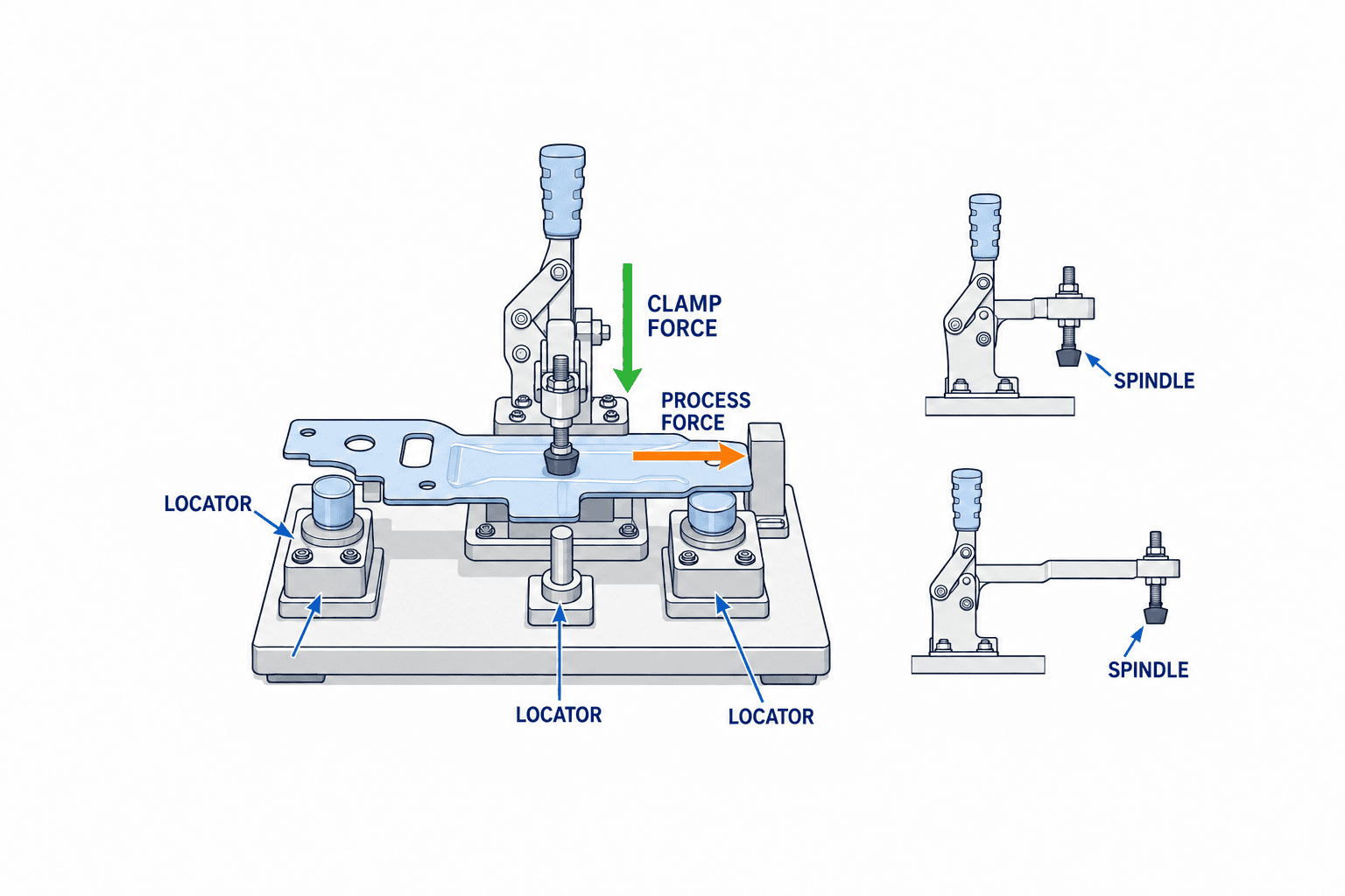
A toggle clamp is a quick-action holding mechanism that closes by moving its linkage past the dead center. The “holding capacity,” which resists external force when closed, and the “clamping force/exerting force,” which is the force applied to the workpiece during closure, are not the same value. Carr Lane’s technical explanation defines holding capacity as the external force the clamp can resist in the locked position without permanent deformation, and clearly states that the actual clamping force depends on spindle position, height adjustment, tip material, and workpiece material. DESTACO’s technical explanation also lists operator force, point of application, mechanical advantage of the linkage, and measurement position on the bar as variables for exerting force. Therefore, you must not simply copy the catalog’s “maximum holding capacity” as the pressing force on the workpiece in your RFP.
Locators for Positioning, Clamps for Holding
Reference positions for machining, welding, and assembly are established by locators such as pins, stoppers, support pads, and V-blocks. The role of the clamp is to keep the workpiece in stable contact with these references and prevent it from moving during the process. If you design the clamp tip to determine the position, then operator force and tip pad wear become the dimensional reference, which is undesirable. First, draw datums, workpiece insertion direction, support points, reaction points, and process load direction on the drawing, and then place the required clamp positions. Especially for thin plates, pressed parts, and plastic components, excessive clamping can deform the shape, causing dimensional changes after removal from the jig. It is more important to determine the minimum holding force required through testing than to simply purchase a stronger model.
Do Not Reduce “Required Force” to a Single Value
In the design table, at minimum, separate columns should be used for the force to seat the workpiece on the locator, the force to resist process external loads, the maximum pressing force the workpiece can tolerate, and the force operators can repeatedly apply. For welding, consider heat input and shrinkage, gun contact, spatter, and jig orientation. For screw tightening, consider tool reaction force and part lifting; for press-fitting, consider axial load and reaction path. Simply observing that “the workpiece did not shift during welding” can overlook crushing, post-weld warping, and permanent deformation of mechanical elements. Plan tests to sequentially measure seating, process, and post-release dimensions using actual workpieces.
Select Horizontal, Vertical, or Plunger Types Based on Workpiece Escape Direction
The MISUMI toggle clamp catalog distinguishes between horizontal, vertical, plunger (side push), latch, and other types. The classification is not based on appearance, but on the movement of the arm or plunger, the space required when open, and the direction of force applied to the workpiece. The selection table should illustrate both the “holding posture when closed” and “interference when open.” Use actual CAD data of candidate models, opening angles, stroke, mounting holes, and spindle adjustment ranges to check even hand movement. Even with similar external shapes, the handle trajectory and part insertion path may interfere.
| Type | Typical Application | Points to Confirm in Advance |
|---|---|---|
| Horizontal Hold-Down | Hold-down jigs where the open handle needs to be stored low | Interference among bar tip, handle, tools, and guards |
| Vertical Hold-Down | Hold-down jigs with sufficient vertical clearance for operation/opening | Interference with robots, guns, and lighting above |
| Plunger/Side Push | Workpieces to be seated laterally against a stopper | Shaft misalignment, side escape, tip rotation, surface pressure |
| Latch/Pull | Configurations to pull lids or two parts together | Hook engagement, spring-back when open, missed latching |
This table does not provide a definitive rule for selecting a model. For example, when using a side push plunger to press a thin plate sideways, if the support surface is insufficient, the plate may lift. Adding a hold-down clamp does not always solve the problem, and adding supports can result in over-constraint. Confirm with prototypes that include the worst-case workpiece tolerances, burrs, surface roughness, surface treatment thickness, and insertion angle.
Do Not Select Horizontal or Vertical Types Based Solely on “Storage Position”
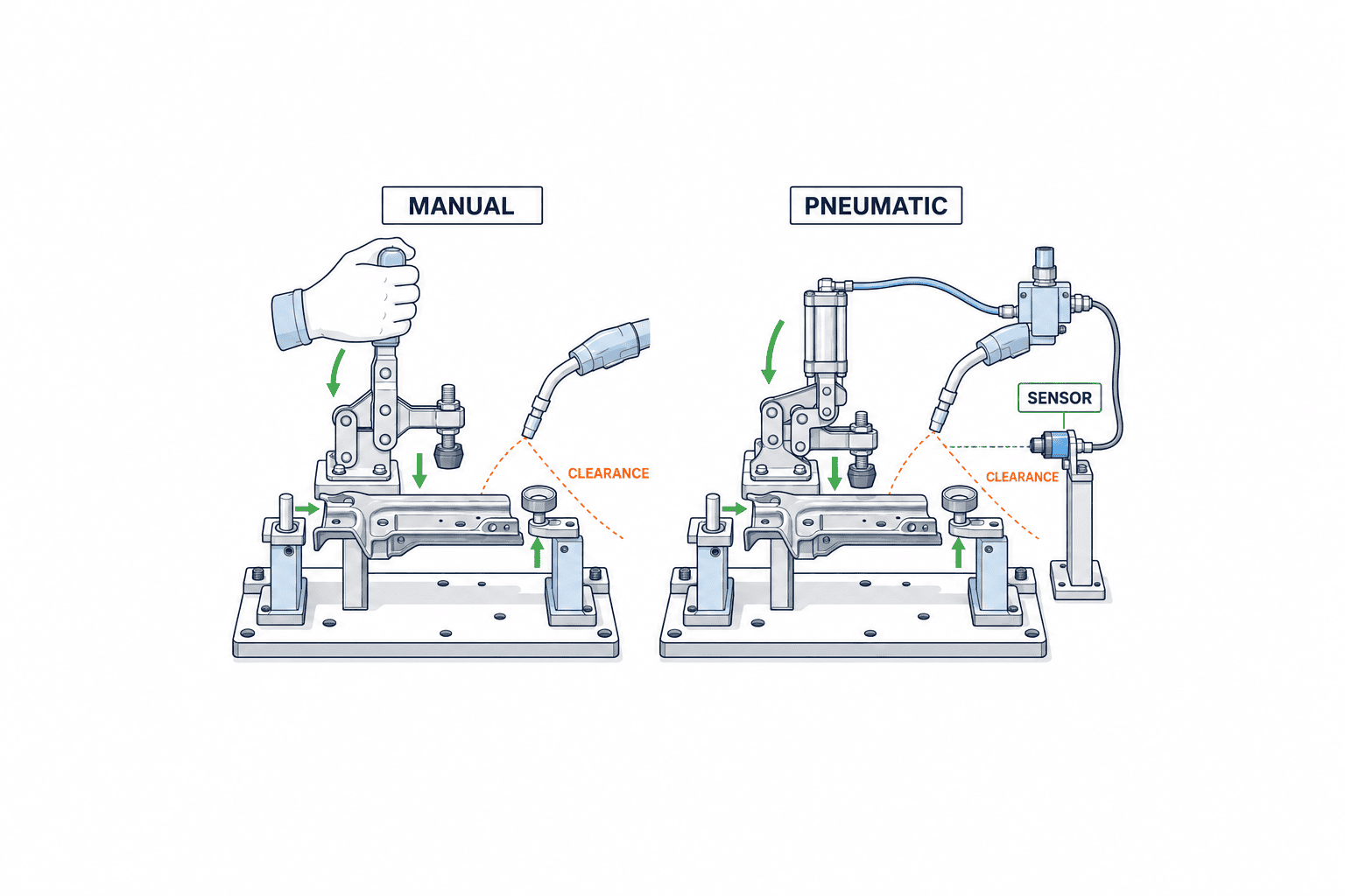
Vertical types have arms that rise significantly when open, making removal easy, but they may interfere with welding guns or robot paths. Horizontal types can reduce overall height, but the operating handle may protrude into side aisles or neighboring jigs. Use CAD or physical mockups to check the envelope in both closed and open states, the range of hand and finger access for operators, and the path for cleaning tools. Indicate left/right orientation on the jig drawing to balance commonality of maintenance parts and workability.
Tip Pad and Arm Position Affect Capacity
Holding capacity is a value based on specific test conditions. Carr Lane specifies that, for hold-down types, the capacity is measured with the spindle positioned close to the handle, and it decreases at the arm tip. Adding long extension arms, rubber tips, or angled contact points deviates from catalog conditions. Confirm with manufacturer specifications and supplier design calculations regarding the feasibility of custom arms, maximum allowable length, reinforcement methods, tip pad hardness/wear, and anti-loosening measures for adjustment screws. Do not just check “the model’s number is sufficient”—ensure “it is sufficient at the actual tip position used.”
Do Not Decide Between Manual or Pneumatic Clamps Based Solely on Cycle Time
Manual clamps do not require piping, valves, or control systems, making them suitable for changeovers and small-lot, high-mix prototyping. However, the actual clamping force can vary depending on the operator, operating angle, and spindle adjustment. Frequent operation may lead to operator fatigue, forgotten tightening, and challenges in confirming the clamp state before starting the process. Pneumatic clamps allow multiple points to be actuated in the same sequence and can be integrated with sensors and PLCs in the design. On the other hand, you must manage pressure fluctuations, piping leaks, valve failures, exhaust, malfunctions, and residual pressure during maintenance. Selection should not be a simple manual-versus-automatic comparison, but rather a process design that includes repeatability of workpiece seating and behavior in abnormal situations.
| Evaluation Item | Manual Confirmation | Pneumatic Confirmation |
|---|---|---|
| Operation | Can the operator clamp safely and ergonomically? | How will you switch between automatic, manual, and setup modes? |
| Workpiece Check | Is tactile feedback and visual confirmation sufficient when clamping? | How will you detect workpiece presence and clamp position? |
| Variability | How will you inspect differences between operators and tip adjustments? | How will you monitor pressure, flow, leaks, and temperature changes? |
| Stop & Recovery | How will you prevent mistakes in releasing and tool removal? | How will you define states for power outage, air pressure drop, emergency stop, and restart? |
| Maintenance | How will you inspect pin, link, and handle wear? | In addition, how will you handle valves, piping, sensors, and residual pressure? |
When comparing cycle times, it is insufficient to look only at clamp open/close seconds. Use measured values that include loading, seating confirmation, confirmation of all clamp points being closed, process execution, unloading, cleaning, and changeover. Simultaneous actuation of multi-point clamps may appear faster, but if the workpiece shifts at the first contact, rework time increases. Consider designing the closing sequence, separating the point that first references the datum from the point that finally holds the workpiece, and compare these options. For guidance on automation investment priorities, refer to Automation Case Studies for Small and Medium Manufacturers in Thailand.
Confirm What Happens When Air Pressure Is Lost for Each Model
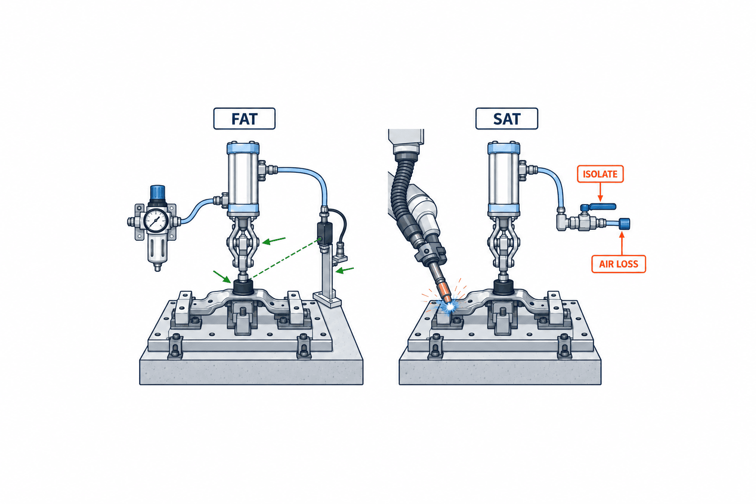
Do not generalize by saying, “Toggle type clamps will hold even if air is lost.” The DESTACO 870-2/871-2 Series explicitly specifies a toggle lock function that mechanically maintains the locked position even if all air pressure is lost. This is a specification unique to that series. It cannot be automatically applied to other models, different circuits, special arms, or worn equipment. For each selected part number, cross-check the mechanical lock conditions at the closed position, power loss, supply pressure drop, hose rupture, valve neutral position, residual pressure, and re-operation upon pressure restoration using the manufacturer’s documentation and the fixture’s circuit diagram.
“Remaining closed” is not always the safest state. In processes where operators need to remove the workpiece, the closed state may hinder rescue. Conversely, releasing while holding a heavy object may result in a drop. The safe state should be determined by hazard assessment of the process. ISO 12100 provides principles for risk assessment and risk reduction for machinery, and ISO 4414 sets out general safety requirements for pneumatic systems and components. For equipment in Thai factories, determine applicable laws and internal standards with the responsible equipment manager; do not declare safety functions based solely on the manufacturer’s mechanical description.
Clamp Position Sensors Are Not Equivalent to Safety Functions
A “clamp closed” signal is useful as a condition in the production sequence, but it does not prove that the workpiece is correctly seated. Consider scenarios where burrs are caught at the pin tip, the wrong part is loaded, or the sensor falsely indicates a closed state due to malfunction. As needed, treat workpiece presence, seating on the reference surface, clamp position, and pressure as separate signals, and detect contradictions among them. When using as part of a safety-related control system, separate risk assessment, required performance, and verification from ordinary process monitoring. Simply including sensors in the quotation does not determine behavior in the event of failure.
Maintenance Air Release Procedures Are Separate from Product Mechanisms
The OSHA 1910.147 standard in the United States stipulates energy isolation, residual energy release, and verification of isolation to prevent unexpected startup or release of stored energy during maintenance. While this does not substitute for Thai legal requirements, it is a primary reference when designing maintenance procedures. Even if the clamp is mechanically locked, residual pressure in cylinders or piping, springs, and the potential energy of unsupported workpieces must be evaluated separately. Include lockout points, exhaust valves, pressure gauges, manual release methods, workpiece support before release, and checks before restart in the fixture handover documentation.
Do Not Rely Solely on Tip Adjustment to Absorb Workpiece Variations
Adjusting the clamp spindle to match the thickness difference between Product A and B may seem simple. However, unless you specify who will make the adjustment, with which gauge, how the setting will be fixed, and whether the contact position changes for borderline workpieces, the clamping force will vary with each setup. When handling multiple product types with a single fixture, measure not only the minimum and maximum dimensions, but also hole positions, bend angles, pre-weld gaps, surface treatments, and burrs, and test the worst-case combinations for each product type. Being within the nominal stroke of the clamp and achieving appropriate clamping force are separate checks.
Trade-Offs Between Adjustment Range and Parts Standardization
Parts with a wide adjustment range help field adaptation but also increase the risk of setting errors. Combine reference gauges, color-coded stop positions, interchangeable tip pads, and product-specific recipes to design so that operators can reliably return to the correct state. However, do not rely solely on color for safety or product identification. When standardizing interchangeable parts, also check the effect of tip shape and material on the workpiece surface. For welded parts, consider spatter adhesion and heat; for assembly, consider scratches, dents, and foreign matter; for locations near food or pharmaceuticals, consider cleanability and material compatibility—each requires different selection criteria.
Review Support and Load Paths Before Adding More Clamps
When the workpiece lifts, adding more clamps is not always the solution. If the first clamp pushes in an inappropriate direction, the second clamp will fix the deformation. Review whether the support point is directly under the process force, whether the reaction force closes into the fixture base, and whether bending is applied to thin walls of the workpiece. If necessary, change the locator, support surface, clamping sequence, or tip shape. Only adopt the plan to increase clamp points after confirming post-release dimensions and process capability. This is where general fixture design principles on positioning apply, but when selecting purchased components, you must specify down to tip position and adjustment limits.
Example of Filling Out the Selection Table in a Real Process
Let’s consider a fixture designed to align the holes and end faces of two stacked thin steel brackets prior to spot welding. The following is a design example for completing RFP items, not actual measured values of a specific manufacturer’s capability. First, the lower bracket’s hole is placed onto a pin and its end face is pushed against a stopper. Next, the upper bracket is placed, and any floating or gaps are checked before closing the clamp. If the closing order is reversed, the upper plate may slip off the locating pin or the initial gap may be forcibly closed, potentially leading to issues. Neither scenario can be distinguished by simply detecting that the “closed sensor is activated.”
In this example, the comparison candidates are a manual hold-down clamp pressing from above and a pneumatic vertical clamp. A side push plunger can assist in seating the end face against the stopper but cannot independently prevent floating between plates. A vertical hold-down clamp may provide easier workpiece loading/unloading space, but if the open arm interferes with the welding gun’s movement, it is unsuitable. Even if a horizontal type fits in terms of overall height, ensure that the operator’s hand does not come too close to spatter during handle operation. With pneumatic types, you can design for two-hand operation or sensor monitoring, but the necessity and safety must be evaluated for the entire process. This comparison cannot be completed based on catalog photos alone.
Test workpieces should include not only good parts at nominal tolerance but also combinations at the tolerance limits for plate thickness, bending, hole position, and initial gap. If the actual variation distribution is unconfirmed, clearly state in the RFP that “final model selection will be determined after measurement,” separating preliminary and final selection. The clamp tip contact point should be determined simultaneously with the welding position, sequence of welds, electrode approach, thermal deformation, and post-release shape. Pressing directly above the support and pressing at a position offset to avoid tool interference will result in different workpiece deformation, so they are not equivalent alternatives.
| Comparison Question | Required Answer in RFP | Evidence to Retain in FAT/SAT |
|---|---|---|
| In which direction is force applied to the actual workpiece? | Tip position, surface shape, adjustment range, relation to support point | Contact marks, seating, post-release shape |
| What receives the process load? | Load path through locator, base, clamp | Observation of shift during process, wear points |
| Can it be closed with the worst-case variant? | Dimensional range and open envelope for each variant | Insertion/removal of workpieces at tolerance limits |
| What happens during a stop? | Valve, mechanical lock, residual pressure, release method | Abnormality test per approved procedure |
If you compare only prices while leaving the answers in the table ambiguous, the lowest bid may require later rework, pad changes, or control modifications. Conversely, if requirements are clarified, you may achieve your objectives with a manual type and simple seating gauge, without resorting to expensive pneumatic systems. The key is not to decide the superiority of a method first, but to compare candidates using the same workpiece, process load, and acceptance test. Procurement, manufacturing, quality, and maintenance should all fill out the same selection table, and differing opinions should be converted into test items.
What to Include in an RFP for Toggle Clamps
If the request for quotation simply states “fixture set with toggle clamp,” suppliers may provisionally select inexpensive standard products, only for interference or insufficient force to be discovered later. At a minimum, include the workpiece drawing and tolerances, process, loading/unloading, load, temperature, spatter, required seating and allowable deformation, operating conditions, cleaning/maintenance, air supply, I/O, and requirements for loss of air in the same version of the RFP. For safety-related requirements, do not just write “complete safety measures”; break them down into hazard sources, desired states, verification methods, and scope of responsibility.
- Product & Process: Product type, revision number, reference surfaces, workpiece mass, actual variation, work sequence, tool/gun paths.
- Clamp Function: Support position, pressing direction, required seating conditions, external process forces, allowable pressing force upper limit, space when open.
- Candidate Model Numbers: Manufacturer, model, catalog version, tip position, arm/pad, mounting method, replacement parts.
- Drive & Control: Manual or pneumatic, pressure range, valves, sensors, PLC signals, states during and after abnormality.
- Testing & Handover: FAT/SAT test workpieces, measurement points, judgment criteria, actual cycle measurements, maintenance procedures, CAD, circuit, and parts lists.
The quotation comparison table should list not only price, but also selected model number, explanation of actual clamping force, conditions for holding capacity, replacement parts, delivery time, local inventory, scope of installation, test items, and warranty assumptions. Unanswered items should not be considered “equivalent” and must be returned as technical queries. For Thai factories, procurement routes for overseas brands, equivalence of alternatives, local sourcing of replacement pads, drawing language, and operator training also affect costs. Do not evaluate based on generalizations such as “Thai-made is cheap” or “imports are safe”; compare by model number and acceptance evidence.
Eliminating Clamp Selection Failure Modes in Design Review
Before drafting the specification, mentally simulate the entire sequence of operations for the finished fixture as used by the operator. The operator picks up the part, places it on the locator, closes the clamp in a posture where the tip does not interfere, inserts the tool, completes processing or welding, and removes the part. If you only check “can the clamp be closed,” you may overlook other failures such as loading the wrong part, finger pinching, partial closure, tool interference, or removing hot parts. In design review, overlay the positions of people, workpieces, fixtures, tools, and sensors for each process step on a single operation diagram, and separately judge operability and safety.
Tip Shifts, Loosens, or Wears
Extending the standard tip with a long screw allows it to reach deeper into the part. However, the contact point moves to the end of the arm, increasing bending and screw loosening. As the pad wears, the seating condition changes even if the handle is fully closed. In design review, illustrate not only the new position but also the tip dimensions and contact surface near the end of service life. Define the adjustment gauge for after replacement, and specify a method so that the adjuster does not overtighten and deform the workpiece. Also confirm that, when maintenance staff revert to a standard pad, the clamp position detection and actual contact are consistent.
Workpiece Can Be Loaded but Not Removed
Even if there is no issue in the closed position CAD, the open arm, handle, hose, or sensor cable may block the workpiece removal path. When lifting a hot welded part at an angle, check which corner will hit first using the actual part or motion simulation. For pneumatic types, include the time to exhaust air and open in the process cycle. If operators have to push hoses aside to remove parts, this can later cause leaks or sensor wire breakage. If the cause of removal difficulty is the locator, address the escape direction of the workpiece rather than enlarging the clamp or extending the stroke.
Only the Closed Signal Is Activated
Even if a position switch is input to the PLC as “closed,” the workpiece may not actually be seated against the support at that moment. With thin workpieces, missing parts, pad dropout, or burrs caught in the workpiece, a structure that only detects the end of the linkage may still generate a closed signal. If seating is required for process quality, design a gap or presence check independent of the closed signal, and set contradictory states as errors. If incorporating into a safety function, a separate configuration and verification in line with hazard assessment is required. Before increasing the number of signals, define in writing what you intend to prove.
Air Remains Even When the Pressure Gauge Reads Zero
Depending on the position of the exhaust valve, check valve, and hose routing, energy may remain near the cylinder even if the equipment-side pressure gauge reads zero. Prepare maintenance procedures specifying which way the workpiece or arm will move during manual release, where to place tools, and where to support the workpiece. Even if the mechanism remains closed upon loss of air, this does not substitute for safe residual pressure management. After modifying the valve circuit, retest the behavior during power failure and loss of air. This issue is not resolved by the clamp catalog alone, but extends to the equipment’s pneumatic circuit and maintenance procedures.
Start Your Comparison from the Definition of “Equivalent Product” During Procurement
When requesting quotations from multiple manufacturers, it is common to treat products as equivalent if their stated holding capacities are similar. However, there are differences in dimensions, operating angles, mounting holes for end attachments, adjustment ranges, occupied space after release, compatible pads, materials, availability of replacement parts, sensor mounting positions, and, for pneumatic types, mechanisms in case of air loss. In comparison tables, evaluate “whether the same task can be performed” for each column, and clearly indicate any parts or drawing revisions that would change with substitution. If switching to Candidate B, do not automatically reuse FAT (Factory Acceptance Test) items completed for Candidate A. Re-test items affected by the change.
In Thailand, differences in lead time between imported and locally sourced products should also be considered. However, inventory status changes daily. The RFP should specify part numbers, expected replacement frequency, initial spares, local ordering sources, and alternative procedures, and responses should be managed with a date at the time of quotation submission. If you select based solely on initial price, a shortage of a single end pad could halt your equipment. Conversely, you should collect actual wear data before purchasing large quantities of replacement parts. Do not treat procurement conditions as fixed predictions; instead, establish operational items specifying when to reconfirm them.
Suppliers should be asked to separately clarify their responsibility for the overall jig design and the single-item conditions guaranteed by the clamp manufacturer. If a standard product is used with an arm length outside the allowable range, referencing the manufacturer’s capacity table does not explain the performance of the completed jig. If workpiece tolerances are not yet finalized, clearly state the quotation conditions as assumptions, and set a gate to reselect the part number after measuring the actual workpiece. This approach allows you to detect, before procurement, any issues where “the quotation was valid, but the mass production part cannot be clamped.”
Conditions for Delaying Final Part Number Selection
Even if product drawings are finalized, if initial press warpage or pre-weld gaps in mass production have not been measured, you should not rush to finalize the clamp part number. Provisionally select candidates and incorporate a short test in the procurement plan to check end contact, seating, and post-process deformation using representative workpieces from the shop floor. Especially when using resin pads or spring-loaded tips, do not confuse the amount of elastic deformation that can be absorbed with the force required to push the part into position. A larger absorption amount is not always better, as it may allow workpiece movement during processing. Record the dimensions and condition of the test workpiece and retain them together with the limit conditions of the selected model.
In the final model selection meeting, separately confirm whether seating was achieved with the most difficult-to-clamp workpiece, whether there is play with the thinnest workpiece, and whether there are indentations on the weakest section. If a single part cannot satisfy all three conditions, use separate evaluation workpieces. For welding, include the release state after heating; for assembly, the posture where tool reaction force is greatest; for inspection, the posture where the measuring probe contacts. Design margin should be demonstrated not only by catalog capacity differences but also by physical evidence at the worst-case workpiece and usage limits. This is the final confirmation linking the part manufacturer’s values to the performance of the completed jig.
Verify More Than Just “Closing” in FAT and SAT
FAT is the stage where the supplier demonstrates that the jig and clamp operate according to specifications. Using actual workpieces or test pieces with known dimensions, record seating, closing/opening, end contact, interference, adjustment range, sensor signals, pressure changes, and abnormal states. Prepare workpieces representing the minimum/maximum product tolerances and warpage, and do not end testing with only good parts. For manual types, have multiple operators close the clamp in the same sequence to observe individual force differences and missed closures. For pneumatic types, design tests based on risk assessment for pressure drop, power outage, emergency stop, re-supply of air, and manual valve operation. Do not attempt to recreate hazardous conditions on-site without a plan.
In SAT, verify with the actual equipment, actual workpieces, actual guns/tools, jig mounting surfaces, supply pressure, safety devices, and operator movement paths. Even mechanisms that passed FAT may yield different results on-site due to hose length, grounding, spatter, tool cables, or adjacent equipment. Acceptance criteria should not be limited to “it moved,” but should be linked to the results of workpiece processing/welding/assembly and measurement methods. For example, when evaluating post-weld shape, distinguish between values measured while clamped and after release. The role of the jig is to constrain during the process, so to guarantee product acceptance, verification must be combined with process conditions.
| Test Item | Evidence to Observe | Troubleshooting When Not Met |
|---|---|---|
| Seating/Repetition | Contact with reference surface, raw data of workpiece position | Locator, burrs, insertion direction, clamping sequence |
| Force/Deformation | End conditions, movement during process, dimensions after release | End position, force, support points, material differences |
| Interference/Operation | Opening/closing envelope, working posture, tool path | Model, left/right orientation, mounting position, guard |
| Failure Mode | State records for air loss, power outage, stop, recovery | Mechanical lock, valve, residual pressure, control, hazard assessment |
| Maintenance | Procedures for replacement, adjustment, shutoff, restart | Documentation, access, spares, training |
Do Not Use “Visual OK” as Acceptance Criteria
For locations where force or position must be measured, specify measuring instruments, calibration status, measurement posture, samples, and judgment rules in the RFP. Even if measurement is difficult, agree on what will be used as a proxy indicator. The clamp’s closed switch alone cannot prove workpiece seating; use separate gap checks, gauges, or post-process dimensions as needed. Record any actual pressure or welding heat input that cannot be tested in FAT as “carry over to SAT,” and decide who will make the final pass/fail judgment and when. Rather than the number of approval stamps, reproducible raw data and records of model/version are more valuable.
Can the Same State Be Restored After Replacement?
If you only check operation at acceptance, performance may deteriorate on the day the end pad or spindle is replaced. Include in the handover the setting dimensions at replacement, reference gauges, tightening methods, anti-loosening measures, trial workpieces, and re-inspection items. Inspect for pin and link wear, handle deformation, pad hardening, and weld spatter adhesion. Decide which changes require stopping use based on manufacturer limits and process-side tolerances. Rather than arbitrarily setting a uniform replacement interval such as “replace all every six months,” it is more rational to record usage count and condition and update the maintenance plan accordingly.
Implementation Procedure in Thai Factories: From Small-Scale Testing to Mass Production Acceptance
First, define current losses in a representative process—whether the issue is workpiece lifting, misalignment, indentations, missed clamping, setup time, or rework will determine the test measurements. Next, record the current jig’s support and clamp points and the actual workpiece variation. Before listing manufacturer candidates, finalize process loads, allowable deformation, and operator movement paths. Test whether a manual standard product is sufficient, and consider pneumatic conversion and monitoring signals if necessary. Ensure that pneumaticization is not the goal itself, and document investment decisions compared to the current method.
In prototyping, do not use a single part number or pad to represent all product types. Use workpieces with tolerance extremes, warpage, surface conditions, and different insertion orientations, and observe both during clamping and after release. For mass production introduction, receive a complete set including part model/version, CAD, circuit diagrams, PLC I/O, replacement parts, cleaning methods, failure/recovery states, and FAT/SAT records. If local maintenance staff can actually perform replacement and adjustment during SAT, reproducibility can be maintained even during night shifts without the supplier present. For internal approval, demonstrate correspondence between issues and evidence, rather than simply stating “the clamp has high capacity.”
Manage Changes After Specification Freeze
If spindle length, end pad, mounting hole, sensor position, valve, or pressure setting are changed after FAT approval, the jig may not be in the same state as at acceptance, even with the same part number. Record the reason for the change, affected product types, re-verification of force and interference, drawing revisions, and handling of old parts on the change form. Especially for welding jigs, changes in gun shape or weld sequence can introduce new loads to the clamp. Do not assume that minor changes do not require re-testing; select and re-execute FAT or SAT items as appropriate for the change. Decide in advance “who approves resumption of use” among purchasing, manufacturing, quality, and maintenance, to prevent temporary repairs during night shifts from becoming permanent specifications.
Frequently Asked Questions
Can the holding capacity of a toggle clamp be used directly as its clamping (exerting) force?
No, it cannot. Holding capacity is defined as the external force that the clamp can resist in the closed position. The actual clamping (exerting) force depends on the operating force, linkage, tip position, adjustment, pad, and the workpiece itself. Always compare the manufacturer’s test conditions with your actual application, and if necessary, measure the force using your actual workpiece.
Which is more suitable for welding jigs: horizontal or vertical toggle clamps?
There is no universal answer. Selection depends on factors such as the path of welding guns or robots, height when open, handle operation, spatter, ease of cleaning, and the direction of workpiece removal. Be sure to check not only the envelope in the closed position but also in the open position.
Will a pneumatic toggle clamp hold the workpiece if air pressure is lost?
This depends on the model and pneumatic circuit. Some products specifically state the presence of a mechanical lock, but you must check the specifications of the candidate model, conditions of wear, and the operation when pressure is lost and restored. Also, separately evaluate whether retaining the workpiece during pressure loss is safe for your process.
What should be checked during FAT, and what should be left for SAT?
During FAT (Factory Acceptance Test), confirm the jig’s seating, opening/closing, interference, sensors, adjustment range, and representative failure conditions. During SAT (Site Acceptance Test), check the actual equipment’s pressure, tool paths, product quality, safety devices, operator movement lines, and maintenance procedures. Record any items carried over and the responsible decision-makers.
Summary
The sequence for selecting toggle clamps is: define product standards and process loads, distinguish between holding capacity and actual clamping force, compare actuation methods and tip positions, and verify variation and the state during pressure loss. Clearly specify model numbers and test conditions in your RFP, confirm mechanisms during FAT, and check process and safety during SAT. This approach reduces the risk of purchasing clamps that meet catalog specifications but cannot be used effectively on site.
Even if you are still comparing clamping methods for assembly or welding jigs in Thailand, you can consult TOMAS TECH. We can help you organize workpiece and process requirements, define RFP comparison criteria, and clarify FAT/SAT acceptance items together.
Reference Information
- Carr Lane — Toggle Clamp Holding Capacity & Clamping Force
- DESTACO — Exerting Force, Clamping Force & Holding Capacity
- DESTACO — 870-2 / 871-2 pneumatic clamps
- MISUMI — Toggle clamp catalogue
- ISO 12100:2010 — Machinery risk assessment
- ISO 4414:2010 — Pneumatic system safety
- OSHA 1910.147 — Hazardous energy control


