


Introduction: ESD Control System Implementation When Records Live Only on Paper and Inside Testers
This article is written for readers in Thailand who are considering ESD control system implementation: plant managers, QA and production engineers, and ESD coordinators at electronic component, EMS, HDD component, automotive electronics and power semiconductor back-end plants. Your EPA (ESD Protected Area) entrance probably has a footwear and wrist strap tester. Yet the results exist only on paper check sheets or in the tester’s own memory. That is a common situation.
At the workstations, operators test their wrist straps by hand at the start of the shift and tick a box on a form. Inspection results for ionizers, bench mats and floors are scattered across individual staff members’ Excel files. When a customer audit or an ANSI/ESD S20.20 certification audit approaches, someone starts collecting forms and files from every line all over again. When a field return comes in and the analysis gets underway, nobody can answer the question: “During that time window, was that operator actually grounded?” If any of this sounds familiar, this article is for you.
The scope here is digitizing the inspection and continuous monitoring records of an ESD (electrostatic discharge) control program and linking them to operators, lines and lots so they can be used for audits and failure analysis. For component handling control in the same kind of electronics plant, see also our article on MSD management system implementation, which covers moisture-sensitive components.
Here is the conclusion up front. ESD control is not finished once the equipment is in place. You need records that can explain what happened between one check and the next. A start-of-shift test shows only the state at the moment of the test. A continuous monitor also catches disconnections that occur mid-shift, but it does not replace periodic verification of work surface resistance to ground, and the monitor itself needs verification. Latent defects caused by ESD are damage that is hard to identify after the fact. That is exactly why there is value in aligning the records of three layers, namely entry testing, continuous monitoring and periodic inspection, by operator ID and timestamp, and linking them to lines and lots on the MES side. Before choosing equipment, decide these three things:
- The scope of the EPA, and which processes are priority processes (those handling components that are sensitive to static electricity)
- What to monitor continuously and what to cover with periodic inspection
- Which key to use to link records to products (lines and lots)
This article does not recommend or rank specific products. Product functions are presented as described in the manufacturers’ documents, and prices are not covered. The cost-benefit estimate in the second half uses hypothetical numbers for this article.
Why Electronics Plants in Thailand Should Review ESD Control Now
First, let us look at where Thailand’s electronics and semiconductor industries stand today. The figures below are stated with their source and scope as published, and we do not add them together or compare them with each other.
- According to a Thailand Board of Investment (BOI) announcement on October 1, 2026, Infineon opened a USD 1.4 billion (THB 48 billion) power semiconductor manufacturing complex in Samut Prakan. It is designed as a highly automated smart factory using robotics, automated material handling and end-to-end digital production systems. Employment across all phases is planned to exceed 5,000 people, and according to Nation Thailand, the current workforce is about 350 people, more than 90% of whom are Thai.
- According to a BOI announcement on September 24, 2026, the National Semiconductor and Advanced Electronics Policy Committee approved Thailand’s first national semiconductor strategy. It sets targets of about USD 80 billion in cumulative investment, about USD 150 billion in annual revenue and more than 230,000 jobs by 2050, and plans to develop 86,600 people by 2030. The focus areas are photonics, power semiconductors and sensors (MEMS).
- According to the same announcement, from 2023 through the first half of 2026, the BOI received 879 investment promotion applications in semiconductors and advanced electronics, worth about USD 27.2 billion (THB 909 billion). This is a cumulative figure on an application basis, not approved amounts or actual investment. The scope includes each stage of chip production, PCBs, HDDs, AI servers and automotive electronic components.
- According to Krungsri Research (published December 17, 2025), Thailand’s HDD exports were worth USD 10 billion in 2024, accounting for 17.5% of global HDD exports on an export value basis, second only to China. Note that this is not a share of production volume. The same report states that electronics accounted for 27.4% of Thailand’s export value in 2024, ranking first among all product categories.
- According to Nation Thailand (September 25, 2026), reporting a Ministry of Commerce announcement, exports in August 2026 were USD 34.62 billion, up 24.3% year on year, the fastest growth in 56 months. Exports of industrial products rose 27.1%, led by computers, ICs and printed circuits.
- According to remarks by the president of the Electronics and Computer Employers’ Association reported by Nation Thailand (August 21, 2026), many of Thailand’s large electronics companies have order backlogs of three to five years. This is a statement by the head of an industry association, not a government statistic.
On the factory floor, these developments show up as more new plants, more new lines and more new operators. ESD control is a system that depends not only on equipment but on every single operator being properly grounded and following procedures correctly. The more operators there are, the larger the volume of training, entry testing and inspection records becomes, until paper and Excel can no longer keep up. If you are going to review how records are kept, now, before headcount grows, is a good time.
ESD Control Basics: Where Static Electricity Comes From and Why It Causes Invisible Damage
Static electricity is generated by entirely ordinary actions such as walking, standing up from a chair or lifting a bag. When a charged person or object touches or comes close to an electronic component, a discharge can occur and damage the inside of the component.
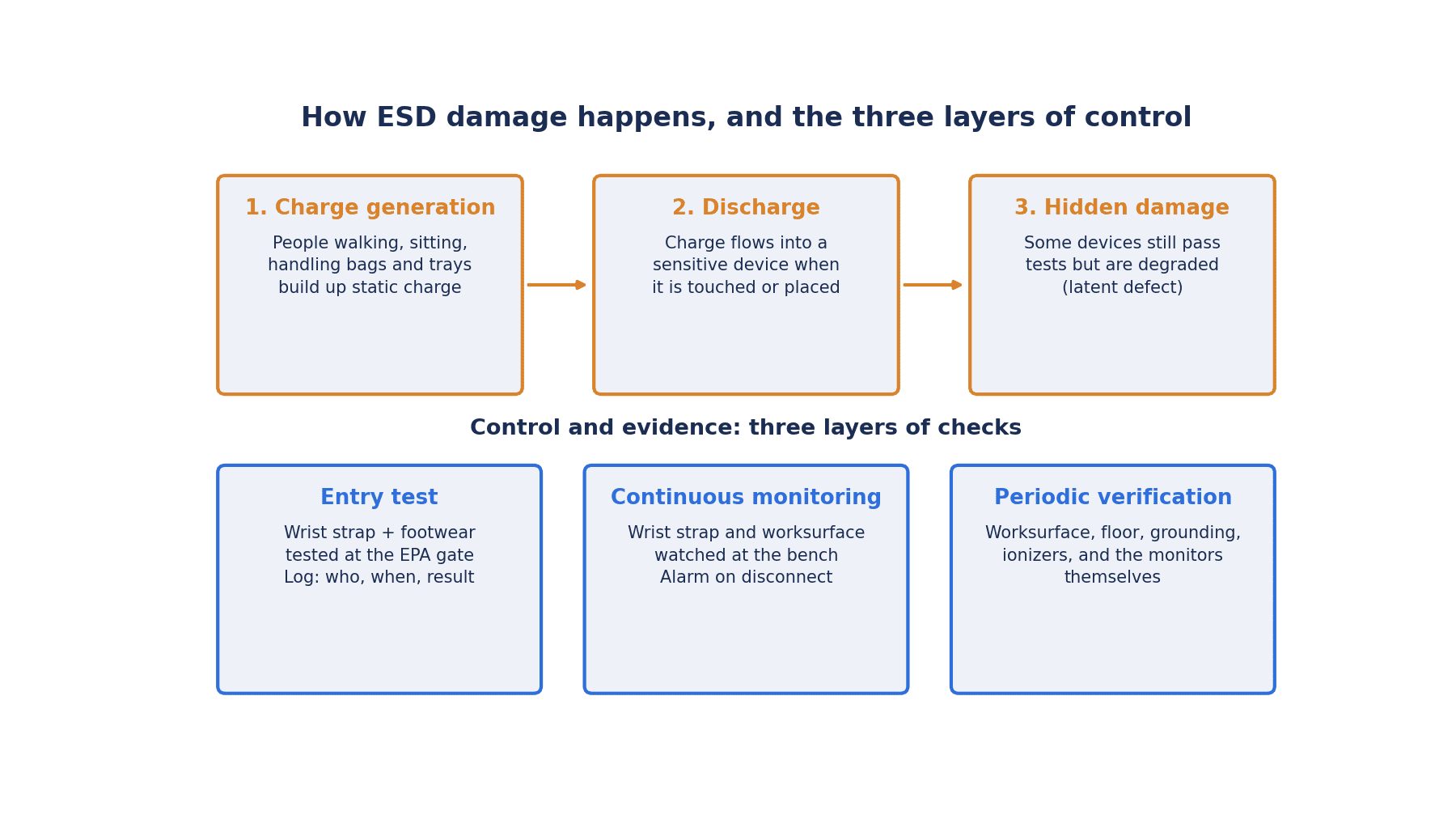
The tricky part is that the damage is not necessarily apparent on the spot. The ESD Association (ESDA) explanatory material states that a component exposed to ESD may be partially degraded yet continue to perform its intended function. For that reason, latent defects are difficult to identify, and the material says they are difficult to prove or detect with current technology. Products containing latent defects may fail early. On the cost of damaged components, it gives a qualitative range from a few cents for a simple diode to several thousand dollars for a complex IC.
Humidity affects the magnitude of charging. The same ESDA explanatory material includes a table of typical electrostatic voltages at different humidity levels. For example, walking across vinyl tile generates 12,000 V at 10-25% relative humidity and 250 V at 65-90%. For a worker at a bench, the figures are 6,000 V and 100 V respectively. This is a table of typical examples, and the measurement conditions are not given. Even so, it shows that charging does not drop to zero even at high humidity. The ESDA explanatory material also states clearly that static generation occurs even at high relative humidity.
Thailand has high outdoor humidity, but inside air-conditioned plants and cleanrooms, humidity can differ from outdoors. You cannot say “Thailand is humid, so ESD is not a concern.” Recording humidity in the EPA also helps in interpreting ESD records. Humidity monitoring inside the plant is covered in our article on temperature and humidity monitoring systems, and cleanroom environmental monitoring in our article on cleanroom environmental monitoring.
On how far charging should be kept down, a useful reference is the 2011 white paper from the Industry Council on ESD Target Levels, an industry group whose participants include IC manufacturers and EMS companies. The white paper states that basic but less-than-ideal controls keep the generated level below 500 V, and proper basic controls keep it below 100 V. Note that the purpose of the white paper was to propose lowering component-level HBM targets for ICs, and that it is a document from 2011.
On the standards side, IEC 61340-5-1:2024 sets its scope as handling parts that withstand 100 V or more under the human body model (HBM) and 200 V or more under the charged device model (CDM), and for isolated conductors it describes a scope that requires keeping them below 35 V. Put the other way around, processes that handle parts more sensitive than this require you to consider stricter controls of your own. This is useful input when deciding on priority processes.
Overview of the ANSI/ESD S20.20 and IEC 61340-5-1 Standards
There are two main families of ESD control program standards: ANSI/ESD S20.20, issued by the ESDA in the United States, and the international standard IEC 61340-5-1. The ESDA store page states clearly that IEC 61340-5-1 is technically equivalent to ANSI/ESD S20.20. The practical approach is to confirm which one your customer specifies, and to build your record system so that it can support either.
The main documents are summarized in the table below. It shows only the number, edition, publication date and what each document covers. It does not cover the numerical values in the standards’ tables or the details of individual clauses. Always confirm numerical requirements in the text of the standard itself.
| Document | Edition, publication date | What it covers |
|---|---|---|
| ANSI/ESD S20.20 | 2021 edition (the ESDA store published a revised version on January 6, 2022; the ESDA document status shows it under revision, with publication expected in 2027) | Development of an ESD control program to protect electrical and electronic parts, assemblies and equipment |
| IEC 61340-5-1 | 2024 edition (Edition 3.0, published May 21, 2024) | General requirements for protecting electronic devices from electrostatic phenomena. Technically equivalent to S20.20 |
| IEC TR 61340-5-2 | 2018 edition (Edition 2.0, published March 28, 2018) | User guide for implementing 5-1. Aligned with the 2016 edition of 5-1 |
| IEC TS 61340-5-4 | 2026 edition (Edition 2.0, published June 5, 2026) | Compliance verification of the technical items of an ESD control program |
| ESD TR53-01-22 | ESDA technical report | Procedures and troubleshooting for compliance verification testing of ESD protective equipment and materials |
| ANSI/ESD S1.1 | 2021 edition | Testing of wrist straps and wrist strap systems. Continuous monitors themselves are out of scope |
| ANSI/ESD STM97.1, STM97.2 | 2025 edition, 2016 edition | Resistance and voltage measurement of footwear and flooring in combination with a person |
| ANSI/ESD STM9.1 | 2022 edition | Resistive characteristics of footwear |
| ANSI/ESD SP3.3, SP3.4 | Both 2026 editions | Periodic verification of ionizers. SP3.4 uses a small test fixture |
| ANSI/ESD STM3.1 | 2024 edition | Test method for ionizers |
The structure of S20.20-2021 can be checked in the table of contents published by the ESDA. Section 7, the administrative requirements, has four parts: 7.1 ESD Control Program Plan, 7.2 Training Plan, 7.3 Product Qualification Plan and 7.4 Compliance Verification Plan. Section 8, the technical requirements, has five parts: 8.1 Grounding and Equipotential Bonding, 8.2 Personnel Grounding, 8.3 EPA (insulators and isolated conductors), 8.4 Packaging and 8.5 Marking. The parts most closely related to digitizing records are 7.2 Training Plan and 7.4 Compliance Verification Plan.
What changed in the 2021 edition is explained in a blog post by the certification body DQS (March 28, 2022). This is secondary information from a certification body. According to it, the 2021 edition was published in December 2021, replacing the 2014 edition, and added a statement that compliance verification of grounding systems is not required. It also says that a note was added to the verification plan to the effect that “being calibrated does not mean the equipment is capable of making the required measurements.” Audits against the new edition were announced to begin in June 2022.
On the IEC side, IEC 61340-5-1:2024 refers to IEC 61340-5-4 (compliance verification testing) from its tables of requirements. IEC 61340-5-4 itself was published in June 2026 as Edition 2.0 of a technical specification (TS). According to the IEC description, it is a major revision of the previous edition and sets out simplified test methods intended for use by competent personnel familiar with operating test equipment. It can be adopted as is, or tailored for your own site provided deviations are documented in the verification plan. Product qualification is out of scope. The ESDA’s TR53 is also positioned as a verification procedure document corresponding to IEC 61340-5-4.
The ESDA operates facility certification programs for S20.20 and IEC 61340-5-1. According to the ESDA, since July 1, 2023, all S20.20 facility certifications have been based on the 2021 edition. IEC 61340-5-1 facility certifications are based on the 2024 edition from June 2025. The ESDA list of certified facilities also includes sites in Thailand.
What an ESD Audit Looks For: The Compliance Verification Plan and Records
An ESD audit asks about more than whether the equipment is in place. It looks at whether you inspected as planned and whether records of that remain.
The text of the 2016 edition of IEC 61340-5-1 is quoted in a technical document from Desco Europe (July 2018). Its gist is as follows. Measurements shall be made in accordance with a compliance verification plan that defines the technical requirements to be verified, the measurement limits and the frequency of verification. Compliance verification records shall be established and maintained as evidence of compliance. The test equipment selected shall be capable of making the measurements defined in the verification plan. We have not checked the clause numbers or wording of the 2024 edition here, but the basic idea of keeping records as evidence is shared with 7.4 of S20.20.
For what happens when records are missing at an audit, a post on the official ESDA forum (2024, posted under the ESDA name) is a useful reference. The post explains audit findings in three categories: “observation,” “minor” and “major.” Examples of minor findings include 5 out of 100 people with expired training, and 2 out of 30 people not wearing wrist straps. The examples given for major findings are the absence of a verification plan, many missing compliance verification records, missing product qualification documentation, and a large quantity of ESD control items that do not meet verification requirements. In other words, even if you do the inspections, the absence of records can be treated as a major nonconformity.
ESDA facility certification works by recertification after a full audit every year. The certification body DQS describes a two-stage audit consisting of Stage 1 and Stage 2. To prepare for yearly audits, a system that can produce a full year of records quickly makes things easier.
On internal audits, the ESDA explanatory material suggests that, after implementation, each department should ideally be audited once a month, or at least around six times a year, adjusted based on results. It also recommends maintaining trend charts and detailed records and compiling them into reports. With paper records, grasping these trends is especially difficult.
ESD control records may also be checked as part of quality records in customer audits and IATF 16949 audits. Designing records that hold up to audits is covered in our article on IATF 16949 traceability, and a system for producing records quickly in customer audits in our article on customer audit traceability.
Three Layers of Checks in an ESD Control Program: Entry Testing, Continuous Monitoring and Periodic Inspection
ESD checks are easier to organize when you think of them as three layers with different characteristics: entry testing at the EPA entrance, continuous monitoring at workstations, and periodic inspection of work surfaces, floors, ionizers and grounding. Below we compare these with the start-of-shift manual test that many plants still use today.
| Method | What it tells you | What it does not tell you | Record unit | Prerequisites |
|---|---|---|---|---|
| Footwear and wrist strap testing at the EPA entrance (linked to a gate) | Whether the operator’s footwear and wrist strap passed the test at the time of entry | Whether a disconnection or detachment occurred after entry | Operator ID, timestamp, test result, resistance value (temperature and humidity on some models) | Reading operator IDs, linking to the gate, setting test limits |
| Continuous monitor at the workstation | Whether grounding of the operator and work surface was maintained during work, including disconnections and poor contact that occurred mid-shift | Whether the work surface resistance to ground is within the specified range (separate periodic verification with a surface resistance meter is required) | Workstation (line), timestamp, alarm occurrence and clearance | Periodic verification and calibration of the monitor itself, assignment of workstations to lines |
| Periodic inspection (work surfaces, floors, ionizers, grounding) | Whether each ESD control item met the verification plan criteria at the time of inspection | What happened between inspections | Equipment ID, inspection date and time, measured value, inspector | Verification plan (items, limits, frequency), calibration and verification of measuring instruments |
| Start-of-shift manual test | Whether the wrist strap passed at the moment of the test | When it failed after the test, and how much product was handled after that | Line on a form (operator name, date, pass/fail) | No missed entries, accurate transcription |
The weakness of the start-of-shift manual test is pointed out succinctly in an explanatory article by Transforming Technologies, a wrist strap tester manufacturer. When a wrist strap fails the start-of-shift test, the question arises: “When did that failure occur, and how much product was handled after the failure?” The same article lists causes of failure such as broken coil cords, dirt on the inside of the cuff, wearing the strap too loosely or over clothing, and high skin resistance.
The ESDA explanatory material states that daily testing of wrist straps used every day is a typical test program, and goes on to say that if components are sensitive enough to require continuous, reliable grounding, continuous monitoring should be considered, and in some cases may be required. It then states that if continuous monitoring is used, daily wrist strap testing can be omitted. Elsewhere, however, it also notes that daily checks are sufficient for some applications, while in other processes continuous monitoring is used to improve the reliability of operator grounding. In other words, there is no need to put every workstation under continuous monitoring. The basic approach is to choose the layer according to the sensitivity of the process.
Whichever layer you choose, one thing holds true: if records carry an operator ID and a timestamp, they can later be linked to other records. Conversely, forms with handwritten operator names, or tester records whose clocks are off, are hard to link later.
What a Continuous Wrist Strap Monitor Can and Cannot Do
As a concrete example of a continuous wrist strap monitor, let us look at the SW Aware Monitor from SCS (Desco Industries). The following is based on the manufacturer’s user guide dated March 2026.
According to the manufacturer’s documents, the SW Aware Monitor continuously monitors one operator and one work surface. It monitors operator grounding using an impedance method and gives an audible and visual alarm in less than 50 milliseconds when the operator unintentionally becomes disconnected from the monitor or when the wrist strap connection point becomes intermittent. For the work surface, it monitors a ground path of less than 10 MΩ. When operators leave their seat, touching the parking snap silences the alarm for about 8 seconds, and if they unplug the cord and connect it to the parking snap during that time, they can step away without triggering a false alarm. It has an Ethernet port and communicates with the company’s management software, the Static Management Program (SMP). The SMP web application shows current status, historical reports and an alarm list, and units can be assigned to lines for management. The test limits are said to be set at the factory and cannot be changed.
According to the same manufacturer’s documents, SMP is software that collects data from the company’s continuous monitors and ionizers so that the state of manufacturing processes can be seen in real time, stores all records in a central database and can be used for quality control.
The manufacturer’s documents state that the SW Aware Monitor eliminates the need for periodic wrist strap testing and the associated records. What must not be overlooked here is a caveat written in the same document. It states clearly that ANSI/ESD S20.20 requires the use of a surface resistance meter for periodic verification of work surface resistance to ground, and that a continuous monitor must not be used in its place. Even if a continuous monitor watches the work surface ground path, periodic verification of work surface resistance to ground still remains as a separate task.
The continuous monitor itself is also subject to checks. The manufacturer’s documents recommend calibrating the SW Aware Monitor once a year and periodically verifying it every 6 to 12 months with a dedicated verification tester. This is the manufacturer’s recommendation. The same document also notes that the monitor is not recommended for homogeneous single-layer mats. The ESDA explanatory material likewise states that testers and continuous monitors need periodic checks and maintenance.
From the standards side, the wrist strap test standard ANSI/ESD S1.1-2021 states clearly within its scope that it does not cover monitoring systems. Looking at the ESDA document status, there is no current standard dedicated to continuous monitors; there is only a 2001 survey report (ESD TR1.0-01-01, dormant). How to confirm the performance of a continuous monitor is therefore determined by the manufacturer’s recommendations and your own verification plan.
In summary, what a continuous wrist strap monitor can do is alert you on the spot when grounding is interrupted during work and record the time it happened. What it cannot do is replace periodic verification of work surface resistance to ground, or remove the need to verify the monitor itself. For a system that delivers continuous monitor alarms beyond the operator’s own bench to team leaders and QA, the approach covered in our article on equipment alarm notification systems applies directly.
Entry Gates and Footwear Testing: Who Passed, When and at What Resistance
A system that tests footwear and wrist straps at the EPA entrance and lets only those who pass go through is an effective way to record entries automatically.
As an example, let us look at the SmartLog Pro SE from EMIT (Desco). According to a document dated April 2021, this tester tests wrist straps and footwear, logs the results and controls entry to the EPA. According to the manufacturer’s documents, each log includes operator identification, test result, resistance value, time, temperature and humidity. Operators can be identified with a proximity card reader, barcode or touch key. Relay terminals can control electric locks or turnstiles so that only people who have passed the predefined ESD tests and are authorized to enter can go through. Even if the network goes down, the unit can continue testing while recording to its internal flash memory. The average test time is 2 seconds.
According to the same document, the web application for management keeps records for the compliance verification plan required by ANSI/ESD S20.20. In addition to vacations, shifts and departments, it can track ESD training certification status and email automatic reports for following up corrective actions.
The point to watch here is the test limits. According to the manufacturer’s documents, the default test limits of the SmartLog Pro SE are 750 kΩ to 10 MΩ for wrist straps and 750 kΩ to 35 MΩ for footwear. These are manufacturer defaults, not values from the standard. You need to configure them to match the values defined in your own verification plan, and keep the settings and their change history in the records.
The same manufacturer’s previous-generation SmartLog V5 with Turnstile (document dated December 2015) tested the wrist strap and footwear resistance paths in under 2 seconds and operated the turnstile on a pass. It had a fail-safe design in which the arm is released during a power failure. Records were stored on the unit and downloaded to a PC.
Let us also look at another manufacturer’s examples. According to the manufacturer’s documents, Access PRO (PGT120 and FastPass turnstile) from Transforming Technologies checks the function of wrist straps and footwear and measures the left and right shoes separately. All test records are kept in a database, recording operator identification, test result, resistance value, time, temperature and humidity. Identification can use an RFID reader, barcode scanner or keypad, and because these are USB HID devices, existing employee badge systems can also be used. To guard against network failures, it can store up to one month of test data internally, and the DataTERM software can centrally manage data from up to 32 testers. Entry is denied on a fail.
According to the manufacturer’s documents, the same company’s PGT130K140 tests wrist straps, heel grounders and footwear simultaneously with three independent measurement circuits, and can also test ESD gloves. By default it uses a 100 V test circuit, which can be changed to 30 V or 50 V. A built-in RFID card reader reads employee information, and the date, time, temperature, user ID and result are recorded in a database. It can also be connected to an automatic door that opens only on a pass.
On the resistance needed to ground a person, according to the ESDA explanatory material, when a person is grounded through flooring and footwear, the resistance to ground of the system including the person, footwear and floor must be less than 1.0×10^9 Ω, and the body voltage in a standard walking voltage test must be less than 100 V; both conditions must be met. These are values from the explanatory material, not the standard’s tables themselves.
What matters in entry test records is that “who,” “when” and “at what value” are kept under an operator ID. Furthermore, if you operate the gate so that operators whose ESD training certification has expired cannot enter, training management and entry management become one connected system. Managing operator competence and qualifications is covered in our article on skill matrix AI implementation.
Ionizer Verification and Periodic Verification of Work Surfaces and Floors
For items whose charge cannot be drained by grounding, such as insulators and isolated conductors, ionizers are used. An ionizer does not keep working indefinitely just because it is installed; its performance needs to be checked periodically.
On the standards side, ANSI/ESD SP3.3-2026 defines the procedure for periodic verification of ionizers. The ESDA store page describes it as providing test procedures for periodically verifying the performance of air ionization devices and systems. The method using a small fixture is SP3.4-2026, and the test method is STM3.1-2024. The ESDA explanatory material lists STM3.1, SP3.3 and TR53 for testing ionizer offset voltage (balance) and discharge time. Confirm specific values and frequencies in the text of these standards.
The key points of ionizer verification are two: balance and discharge time. As a product example, let us look at the Ion Pro benchtop ionizer from SCS. According to the manufacturer’s documents (user guide dated December 2021), this model monitors its own offset voltage (balance) and discharge time, and raises an alarm if the offset voltage exceeds its limit or if the discharge time becomes longer than 4.5 seconds. In the specification table, the offset voltage alarm threshold is about ±35 V in standard mode and about ±7 V in CE mode. These are the manufacturer’s alarm thresholds. Via Ethernet, it can send balance and discharge time status to the SMP mentioned earlier. The manufacturer recommends calibration once a year and recommends periodically measuring balance and discharge time with a charged plate monitor (CPM). Cleaning the electrodes (emitters) is routine maintenance.
Periodic verification of work surfaces and floors is also essential. According to the ESDA explanatory material, work surfaces are required to have a resistance to ground of 1.0×10^6 to 1.0×10^9 Ω. When groundable garments are used, the resistance of the whole system including the person, garment and ground cord is given as less than 35 MΩ. Both are values from the explanatory material. As we saw in the previous section, work surface resistance to ground cannot be substituted by a continuous monitor and requires periodic verification with a surface resistance meter.
Inspection frequency is determined by your own compliance verification plan. Decide it based on customer requirements, process sensitivity and trends in past inspection results, and record the rationale in the plan as well; this makes it easier to explain during audits. Lists of inspection frequencies circulate online, but some of them cannot be traced to the text of the standards, so take care not to treat them as recommendations of the standards.
The basics of digitizing periodic inspection records are to assign IDs to the equipment being inspected (workstations, mats, floor zones, ionizers, grounding points), have the inspector read the ID with a handheld terminal or tablet, and enter measured values on the spot. This removes the effort of writing on paper and transcribing later, and missed inspections become visible on screen. Choosing terminals for electronic records on the shop floor is covered in our article on handheld terminal implementation.
The surface resistance meters and CPMs used for inspections, as well as entry testers and continuous monitors, are subject to calibration and verification. The DQS explanation introduces a note in S20.20-2021 to the effect that “being calibrated does not mean the equipment is capable of making the required measurements.” Beyond keeping calibration due dates, you need to confirm that the instrument can make the measurements defined in the verification plan. For managing instrument registers and due dates, see our article on calibration management systems.
Designing ESD Traceability: From Operator ID and Timestamp to Lines and Lots
This is the part of the article we most want to get across. On their own, entry test, continuous monitoring and periodic inspection records are merely evidence that “ESD controls were in place.” To use them in product failure analysis and audits, you need to be able to trace which products were made under which ESD conditions.
First, let us organize the record items that can be read from the manufacturers’ documents. Entry testers record operator ID, test result, resistance value, time, temperature and humidity. Continuous monitors hold line assignments and alarm history. Ionizers send balance and discharge time status. The management software of entry testers also handles training certification status.
On the other hand, the documents for the products reviewed here do not explicitly mention any function for linking records to lots or production orders. The keys of ESD equipment logs are operator ID and timestamp, or unit and line. Linking to lots should therefore be considered not a function of ESD equipment but something to be designed on the MES or traceability system side.
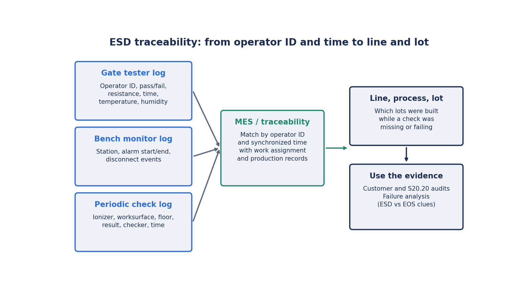
The linking approach is as follows:
- From entry test records (operator ID, timestamp), you know that the operator entered the EPA correctly that day
- The MES side holds operator assignment records (which operator was at which process on which line, and when)
- The MES side holds production records (which lot or serial number was processed at which process, and when)
- Continuous monitoring and periodic inspection records (workstation, line, timestamp) are overlaid with operator assignments and lines
- As a result, for a given lot you can answer: “During the processing time window, had the operator in charge passed the entry test?”, “Were there any grounding alarms at that workstation?” and “Were the ionizer and work surface inspections for that line within their validity period?”
The linchpin of this design is time. If the clocks of entry testers, continuous monitors, ionizers and the MES are out of sync, overlaying time windows does not work. Methods for aligning the clocks of equipment in the plant are covered in our article on factory time synchronization. Also, time-series data that keeps growing, such as continuous monitor and ionizer status, can be analyzed alongside other process data if it is collected in the plant’s data platform rather than left inside the ESD equipment’s management software. Our article on industrial historian selection is also a useful reference.
Operator assignment records are the weakest point in many plants. Unless you introduce a mechanism such as scanning employee badges when operators enter a line, or entering the operator ID as part of the start-of-work operation in the MES, entry test records and lots will not connect. If you think of this not as a new system for ESD but as an effort to improve the accuracy of production records, it can serve other purposes as well.
Linking at the level of lots and serial numbers is covered in detail in our article on electronics traceability and our article on serial number management systems. How fine-grained the links should be depends on customer requirements and how far you want to narrow the scope when something goes wrong. The retention period for records is also determined by customer requirements and internal rules.
Responding to Abnormalities: Stop, Narrow the Scope, Send for Analysis
One purpose of collecting records is to be able to act correctly when an abnormality occurs. The response flow described here is one example of what each company defines as its own procedure.
When a continuous monitor raises an alarm, first stop work, check how the wrist strap is worn and connected, and retest. Then identify the products handled at that workstation during the time window in which the alarm was active. With the linking described in the previous section, you can pull out the relevant production records and lots from the alarm start and clear times. Without the linking, you tend to end up suspecting all of that day’s products.
The same applies when a start-of-shift manual test fails. Products handled between the previous pass and that failure become subject to review. At workstations without continuous monitors, this time window is larger. This is one of the reasons for installing continuous monitors in priority processes.
When periodic inspection finds an ionizer or work surface out of specification, the products processed on that line between the previous pass and this inspection fall within the scope. The longer the inspection interval, the wider the scope, so when deciding inspection frequency, also take into account the size of this “scope to suspect if something is out of specification.”
How to handle identified products (quarantine, additional inspection, rework or scrap) is decided by product criticality and customer requirements. The flow from quarantine to reinspection is covered in our article on manufacturing rework control systems. Note also that some damage cannot be seen in visual inspection of solder joints. For the role and limits of visual inspection, see our article on solder joint inspection AI.
In field return analysis, it is also risky to suspect only ESD. The Industry Council on ESD Target Levels white paper (August 2016) states that electrical overstress (EOS) damage signatures are the most frequently reported cause of IC and system returns. In a 2016 industry survey introduced in the same white paper, respondents reported that more than 20% of all failures were EOS-related, or that 30% of electrical failures were EOS-related. This is an aggregation of known causes as reported by each respondent. The white paper further points out that ESD accounts for only a small portion of EOS damage, and that while many manufacturers spend time on ESD audits of their factories, this resolves only part of EOS-related damage. It also states that EOS damage can occur from poor grounding practices.
What follows is this article’s own view. To distinguish between ESD and EOS, records of the process state at the time serve as material in addition to damage analysis. If there is a record that grounding was solid during the time window in which the product was handled, you can lower the likelihood of ESD and turn your attention to other causes. Conversely, if the time window overlaps with grounding alarms or failed inspections, that is a reason to investigate the possibility of ESD in more detail. Records do not determine the cause conclusively, but they help set the direction of the analysis.
Training and Change Management
The administrative requirements of S20.20-2021 include 7.2 Training Plan. Because ESD control depends on operator behavior, training is at the core of the controls. As we saw earlier, expired training was listed as an example of an audit finding in the post on the official ESDA forum.
When digitizing training records, there are examples such as the SmartLog Pro SE discussed earlier, whose management software for entry testers is stated in the manufacturer’s documents to be able to track ESD training certification. If training records and entry records are managed under the same operator ID, you can notice operators whose training has expired before they enter the EPA.
As we saw in the second section, new plants and new operators are expected to keep increasing in Thailand. According to a BOI announcement on August 27, 2026, the Skill Bridge initiative for developing technical personnel plans to train more than 60,000 technicians through 35 curricula. The more people enter the plant, the heavier the management of ESD training at hiring, periodic retraining and training on transfer becomes. Tracking expiry dates on paper rosters tends to break down as headcount grows.
Change management is also closely tied to ESD control. Rearranging workstations, introducing new ionizers, changing mat or footwear brands and adding lines all change the assumptions of ESD control. Unless you update the EPA scope, verification plan, equipment IDs and the assignment of continuous monitors to lines with each such change, records and the shop floor drift apart. Recording and managing 4M changes is covered in our article on 4M change management systems. For incorporating wrist strap wearing methods and alarm response procedures into shop floor work instructions and reliably delivering revisions, see our article on electronic work instructions.
Requirements to Include in the RFP
The table below summarizes requirements you should include in an RFP (request for proposal) when outsourcing ESD control system implementation. The scope changes significantly depending on whether the system is completed within the ESD equipment management software alone or integrated with the MES or traceability system.
| Item | What to write in the RFP | Points to check |
|---|---|---|
| Target equipment | List, quantity and installation locations of entry testers (gates), continuous monitors, ionizers and inspection terminals | Manufacturer and model of existing equipment, communication method (Ethernet, USB, on-device storage only) |
| Data items and intervals | Test results, resistance values, alarm occurrence and clearance, ionizer balance and discharge time status, temperature and humidity | Separating items that can be obtained from equipment from items that cannot |
| Operator ID method | Consistency with existing systems such as employee badges (RFID cards) and barcodes | Whether the same ID can be used across entry testers, the MES and training records |
| Lot linking method | Linking via operator assignment records, production record timestamps and lines | The boundary between data held on the MES side and data held on the ESD side |
| How thresholds are held | Where test limits and inspection criteria are configured and how they are changed | Whether change history (who, when, from what to what) is kept. Distinction between manufacturer defaults and your own values |
| Alarm notification | Recipients, means of notification and escalation for continuous monitor and ionizer alarms | Recipients during night shifts and holidays |
| Retention during network outages | Retention of records on the device and automatic transmission after recovery | Retention period and number of records, method of detecting gaps |
| Screens and reports | Status by line, list of overdue inspections, output of verification records for audits | Whether records for the period required in an audit can be produced quickly |
| Retention period and backup | Record retention period, backup frequency and storage location | Whether these meet customer requirements and internal rules |
| Time synchronization | Time synchronization method for all equipment and servers | Whether time drift can be monitored |
| Permissions | How permissions for viewing, input, configuration changes and approval are divided | Whether only a limited set of people can change thresholds |
| MES/ERP integration | Integration method with operator assignments, production records and lot information | Direction and frequency of integration, retransmission on failure |
| Calibration and verification | Calibration due dates and verification records for entry testers, continuous monitors and measuring instruments | Integration with the calibration management system |
| Training and maintenance | Training for ESD coordinators, team leaders and operators, and the post-implementation maintenance setup | Screens and training materials in Thai, local support |
In the RFP, write down not just whether a function exists but also “how that function will be confirmed in acceptance testing.” This lets you carry it straight into the FAT/SAT in the next section.
FAT/SAT and Acceptance Criteria
In FAT (factory acceptance test) and SAT (site acceptance test), you confirm that records are kept without gaps and linked correctly. Numerical targets are something you set yourself. Below we show examples of how targets can be set, but these are not industry standards.
FAT (testing in a simulated environment)
- Feed simulated data and confirm that entry tests, continuous monitor alarms, ionizer status and inspection entries are all recorded in the database. As an example, set zero missing records as the target
- Trigger continuous monitor alarms in simulation and confirm that notifications reach the configured recipients and that alarm start and clear times are recorded
- Deliberately cut the network and confirm that records are retained on the device and that no records are lost when they are transmitted after recovery
- Change thresholds and confirm that change history is kept and that users without permission cannot make changes
- Output audit reports and confirm that records matching the items and periods in the verification plan are produced
SAT (testing on actual lines)
- Operate on actual lines for a set period (several weeks, as an example) and confirm the record rate. Reconcile the number of entry tests against the number of entries seen in other records such as attendance
- Confirm the operator ID read rate. Also test the procedure for read failures
- Confirm the lot linking rate. Look at the proportion of production records that could be linked to operator assignment records and entry test records
- Confirm the time drift between devices. Decide the acceptable range of drift yourself
- Confirm how long it takes for continuous monitor alarms to reach the actual notification recipients on the shop floor
- During the transition period, keep the existing paper records in parallel and reconcile them against the electronic records. If there are discrepancies, investigate the cause before stopping the paper records
We recommend that the ESD coordinator actually run a practice audit during the SAT period. Measuring how many minutes it takes to answer the question “Please show the ESD conditions at the time for this lot” gives a clear picture of how well the system works.
Cost and Benefit Model Estimate (Hypothetical Numbers)
All the numbers from here on are hypothetical numbers for this article. We could not confirm official prices for ESD control equipment and software, so costs are also placeholders. We have not been able to confirm primary data on the rate of effect from continuous monitors either, and all effect rates are assumptions. Please use this as a framework for your own estimate.
Assumed plant: A Japanese electronic component or EMS plant in Thailand. 300 operators inside the EPA, 250 workstations, two shifts, 250 operating days per year, 6 EPA entrances.
Current costs (baseline, annual)
| Cost bucket | Baseline (per year) |
|---|---|
| Internal defects suspected to be ESD-related (rework, scrap) | 1,500,000 THB |
| Analysis, sorting and replacement for customer returns suspected of ESD/EOS | 1,000,000 THB |
| Labor for paper inspection records (filling in daily tests, transcription, collection before audits) | 600,000 THB (2,000 hours × 300 THB) |
Configuration A: Log Integration of Entrance Testers and Linking to Lines and Lots
This configuration includes log integration of the testers at the 6 EPA entrances, software that links operator IDs to lines and lots, and electronic records for ionizer and workstation inspections. No continuous monitors are purchased. The initial cost is set at 1,800,000 THB and the annual operating cost at 250,000 THB.
| Effect (assumed) | Calculation | Annual effect |
|---|---|---|
| Internal defects reduced by 10% | 1,500,000 × 10% | 150,000 THB |
| Return handling reduced by 15% | 1,000,000 × 15% | 150,000 THB |
| Record-keeping labor reduced by 60% | 600,000 × 60% | 360,000 THB |
| Total effect | 150,000 + 150,000 + 360,000 | 660,000 THB |
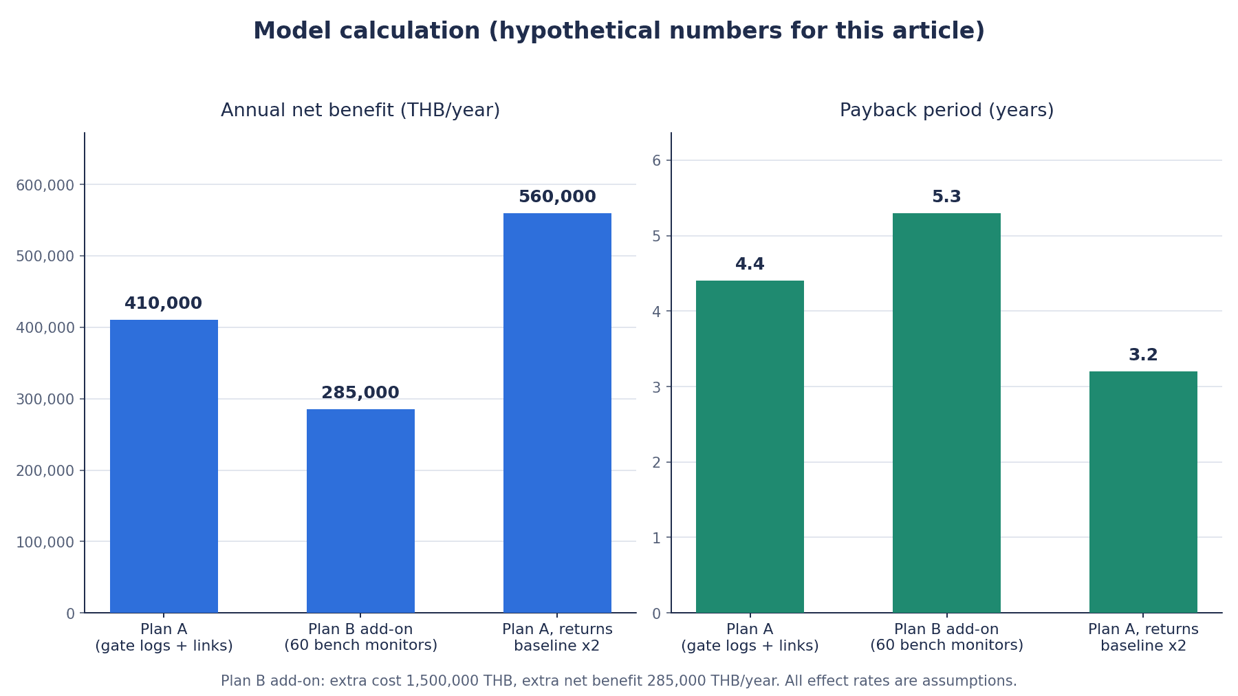
The net effect is 660,000 − 250,000 = 410,000 THB/year, and the payback period is 1,800,000 ÷ 410,000 ≈ about 4.4 years.
Configuration B: Configuration A Plus Continuous Monitors on 60 Workstations in Priority Processes
Continuous monitors are installed on 60 workstations in priority processes that handle components sensitive to static electricity. This is evaluated as an addition after Configuration A is in place. Continuous monitors are assumed to cost 25,000 THB per unit, giving an additional initial cost of 60 × 25,000 = 1,500,000 THB, and the additional annual operating cost is set at 100,000 THB.
| Additional effect (assumed; rates applied to the baseline) | Calculation | Annual effect |
|---|---|---|
| Internal defects reduced by a further 15% | 1,500,000 × 15% | 225,000 THB |
| Return handling reduced by a further 10% | 1,000,000 × 10% | 100,000 THB |
| Record-keeping labor reduced by a further 10% | 600,000 × 10% | 60,000 THB |
| Total additional effect | 225,000 + 100,000 + 60,000 | 385,000 THB |
The additional net effect is 385,000 − 100,000 = 285,000 THB/year, and the payback period for the addition is 1,500,000 ÷ 285,000 ≈ about 5.3 years.
Sensitivity: If the Return Handling Baseline Were Doubled (Configuration A)
If the baseline for analysis, sorting and replacement for customer returns were doubled to 2,000,000 THB/year, the 15% reduction in return handling under Configuration A would be 300,000 THB. The total effect would be 150,000 + 300,000 + 360,000 = 810,000 THB/year, the net effect 810,000 − 250,000 = 560,000 THB/year, and the payback period 1,800,000 ÷ 560,000 ≈ about 3.2 years.
What the Estimate Shows
- In Configuration A, 360,000 THB of the 660,000 THB/year effect comes from reduced record-keeping labor. Simply replacing paper records by digitizing entry test and inspection records and linking them to lots gives a payback period of about 4.4 years
- Under these conditions, the continuous monitors in Configuration B take about 5.3 years to pay back the addition. Rather than installing them uniformly on all 250 workstations, you need to decide to focus on priority processes that handle components sensitive to static electricity
- The larger a plant’s return handling costs, the greater the effect of linking. In the sensitivity case, the payback period for Configuration A shortens to about 3.2 years
The additional effects of Configuration B are set as rates applied to the baseline, not to the amount remaining after Configuration A. Also, the impact of receiving a major finding in an audit, maintaining certification and business relationships, and winning new orders are not included in this estimate.
Frequently Asked Questions
What is an ESD control system?
It is a system for collecting and managing the inspection and monitoring records of an ESD (electrostatic discharge) control program. It digitizes records such as footwear and wrist strap tests at the EPA entrance, continuous monitors at workstations, periodic inspections of ionizers and work surfaces, and training, so they can be used in audits and failure analysis. In this article, we also include linking these records to lines and lots on the MES side, using operator ID and timestamp as keys. Note that the documents from the ESD equipment manufacturers reviewed for this article do not explicitly mention a function for linking to lots.
Where should a factory start its ESD control program?
Start by deciding the scope of the EPA and the priority processes that handle components sensitive to static electricity. Then, following S20.20 or IEC 61340-5-1, put in place an ESD control program plan, a training plan and a compliance verification plan. In digitizing records, collecting the logs from the testers already installed at EPA entrances in many plants is an easy first step to tackle. In this article’s hypothetical estimate as well, log integration of entrance testers and digitization of inspection records (Configuration A) gave a payback period of about 4.4 years.
With a continuous wrist strap monitor, is daily testing unnecessary?
The ESDA explanatory material states that if continuous monitoring is used, daily wrist strap testing can be omitted. However, that does not make all inspections unnecessary. The manufacturer’s documents also state clearly that periodic verification of work surface resistance to ground must be done with a surface resistance meter and cannot be replaced by a continuous monitor. Calibration and periodic verification of the continuous monitor itself are also needed. Decide which workstations get continuous monitoring and which use daily testing based on process sensitivity, and write it into the verification plan.
What is checked in an ESD audit?
In addition to whether the equipment is in place, auditors look at whether inspections were done according to the verification plan and whether the records remain. In a post on the official ESDA forum (2024), the absence of a verification plan and many missing compliance verification records are given as examples of major findings. Expired training and operators not wearing wrist straps are examples of minor findings. Because ESDA facility certification is renewed through a full audit every year, being able to produce a year’s worth of records quickly is important.
What is the difference between ANSI/ESD S20.20 and IEC 61340-5-1?
S20.20 is a standard from the ESDA in the United States, and IEC 61340-5-1 is an international standard. The ESDA states that the two are technically equivalent. The current editions are the 2021 edition of S20.20 and the 2024 edition of IEC 61340-5-1. On the IEC side, compliance verification testing is separated into IEC 61340-5-4, whose 2026 edition was published in June 2026. Which standard is required differs by customer, so the practical approach is to build your record system so that it can support audits against both.
What does ionizer verification check?
Mainly two things: offset voltage (balance) and discharge time. The periodic verification procedure is in ANSI/ESD SP3.3-2026, the method using a small fixture in SP3.4-2026, and the test method in STM3.1-2024. According to the manufacturers’ documents, some models monitor their own balance and discharge time, raise alarms and can send that status over the network. Even in that case, the alarm thresholds are manufacturer settings and are not necessarily the same as values in the standards. Also keep records of maintenance, such as electrode cleaning, and of calibration.
Is ESD control necessary in Thailand even though humidity is high?
Yes. The ESDA explanatory material states clearly that static generation occurs even at high relative humidity. In the same material’s table of typical examples, charging voltage falls under high-humidity conditions but does not reach zero (the table does not give measurement conditions). In addition, humidity inside air-conditioned plants and cleanrooms can differ from outdoors. Recording EPA humidity and making it viewable together with ESD records gives you added assurance.
Summary
- ESD control is not finished once the equipment is in place. You need records that can explain what happened between one check and the next
- Decide three things first: the EPA scope and priority processes, what to monitor continuously and what to cover with periodic inspection, and which key to use to link records to products
- Think of checks in three layers: entry testing, continuous monitoring and periodic inspection. A start-of-shift manual test shows only the state at the moment of the test
- A continuous wrist strap monitor also catches mid-shift disconnections, but it does not replace periodic verification of work surface resistance to ground, and the monitor itself needs calibration and verification
- Test limits and alarm thresholds of entry testers and ionizers are manufacturer defaults and are not necessarily the same as values in the standards. Manage the values in your own verification plan and their change history
- The keys of ESD equipment logs are operator ID and timestamp. Design linking to lines and lots on the MES side, which holds operator assignments and production records, and keep clocks synchronized
- In audits, missing records themselves can become a major finding. In return analysis, records from the time help as material for distinguishing between ESD and EOS
- In the estimate using hypothetical numbers, log integration of entrance testers and digitization of inspection records (Configuration A) gives a net effect of 410,000 THB/year and a payback of about 4.4 years. Adding continuous monitors to 60 workstations in priority processes (Configuration B) takes about 5.3 years to pay back the addition, so a decision to narrow the scope is needed
TOMAS TECH can help even at an early stage, such as organizing your EPA scope and priority processes or taking stock of which records can be obtained from your existing testers. Please contact us through this form.
References
- https://www.esda.org/store/standards/product/314/ansiesd-s20-20-2021/
- https://esda.org/assets/Store/ToC/ANSI-ESD-S20.20-2021.pdf
- https://www.esda.org/assets/Documents/Master-Standards-status-for-website.pdf
- https://www.dqsglobal.com/en/explore/blog/hk/release-of-ansi-esd-s20.20-2021
- https://www.dqsglobal.com/en/certify/esd-20.20-certification
- https://webstore.iec.ch/publication/74748
- https://www.evs.ee/et/iec-61340-5-1-2024
- https://webstore.iec.ch/publication/28047
- https://webstore.iec.ch/en/publication/74749
- https://www.esda.org/store/standards/product/339/esd-tr53-01-22
- https://www.esda.org/store/standards/product/70/ansiesd-s1-1-2021
- https://www.esda.org/store/standards/product/465/ansiesd-sp3-3-2026/
- https://www.esda.org/esd-overview/esd-fundamentals/part-1-an-introduction-to-esd/
- https://www.esda.org/esd-overview/esd-fundamentals/part-3-basic-esd-control-procedures-and-materials/
- https://www.esda.org/esd-overview/esd-fundamentals/part-4-training-and-auditing/
- https://www.esda.org/certification/eosesd-association-esd-facility-certification/
- https://forum.esda.org/t/guidance-on-esd-control-program-audit-findings/686
- https://www.esda.org/assets/IndustryCouncilOnESDTargetLevels_WP1.pdf
- https://www.esda.org/assets/IndustryCouncilOnESDTargetLevels_WP4.pdf
- https://assets.testequity.com/te1/Documents/pdf/scs/SCS_770151_SW-Aware-Monitor-with-North-America-Power-Adapter_User-Guide_0326.pdf
- https://www.farnell.com/datasheets/3665396.pdf
- https://www.farnell.com/datasheets/3216229.pdf
- https://www.farnell.com/datasheets/2831680.pdf
- https://www.descoindustries.com/PDF/TB-6585.pdf
- https://transforming-technologies.com/product/access-pro-100-pgt120-tester-and-fastpass-turnstile-system/
- https://transforming-technologies.com/?p=251618
- https://transforming-technologies.com/esd-fyi/esd-wrist-strap-testing-and-monitoring/
- https://www.krungsri.com/en/research/industry/industry-outlook/hi-tech-industries/electronics/io/electronics-2026-2028
- https://www.boi.go.th/upload/content/PR166_2569EN.pdf
- https://www.boi.go.th/upload/content/PR171_2569EN.pdf
- https://www.boi.go.th/upload/content/PR144_2569EN.pdf
- https://www.nationthailand.com/business/tech/40071760
- https://www.nationthailand.com/business/economy/40071468
- https://www.nationthailand.com/business/trade/40070085


