


When a factory in Thailand installs or replaces inverter control, selecting a drive by motor kW alone can push serious problems into the final commissioning window: overcurrent during acceleration, DC-bus overvoltage during stopping, motor insulation stress, PLC communication mismatches, EMC noise, or an incomplete safety circuit. This guide covers the work that begins after the technology choice: procuring, integrating, changing over, and handing over a maintainable variable-frequency drive (VFD) system. It connects load and motor compatibility, braking and regeneration, cables and earthing, harmonics, STO, PLC/fieldbus contracts, RFP requirements, FAT/SAT, rollback, backups, and training.
Scope: completing a VFD project, not repeating a technology comparison
Our earlier servo-versus-inverter comparison helps readers choose according to positioning, speed, and torque requirements. This article assumes that a VFD is already a credible direction and focuses on completing selection, design, procurement, verification, cutover, and handover.
If precise positioning or multi-axis synchronization is the central need, first revisit the servo control system integration guide for Thailand. For pumps, fans, conveyors, mixers, extruders, and winders where variable speed and process coordination are central, a VFD can be appropriate. However, the U.S. DOE motor and drive sourcebook cautions that VFDs are not suitable for every application and that savings depend on the load and operating profile. An RFP should never promise a fixed saving merely because a VFD is installed.
Define the inverter-control boundary first
Projects fail when the drive datasheet and the system acceptance criteria are separate. Create one requirements-boundary sheet shared by mechanical, electrical, controls, safety, OT, maintenance, and procurement owners.
| Requirement area | Minimum information | Acceptance evidence |
|---|---|---|
| Process | Minimum/rated/maximum speed, ramps, continuous or intermittent duty, reversal | Measurements and trends at defined operating points |
| Load | Variable/constant torque, constant power, inertia, shock, jam case | Load calculation and current/torque logs |
| Motor | Nameplate, insulation, speed range, cooling, bearings, temperature sensing | Compatibility statement and temperature record |
| Supply | Voltage, frequency, fault level, transformer, earthing, generator mode | Single-line diagram and power-quality measurements |
| Control | PLC, network, I/O, command owner, fault behavior | Signal list, state transitions, communication test |
| Safety | Risk assessment, stop functions, PL/SIL target, restart prevention | Calculation, wiring inspection, functional test |
| Environment | Temperature, humidity, dust, corrosive gas, altitude, enclosure cooling | Site survey and heat calculation |
| Operations | Backup, spares, recovery time, training, change control | Restore test, asset register, signed handover |
Do not hide an unknown behind “vendor standard.” Record it as an open item with the method, owner, and date for resolving it through site measurement, OEM confirmation, or existing production logs.
Step 1: size from load and duty, not kW alone
Evaluate current, torque, and time
A VFD retrofit is not necessarily a like-for-like kW replacement. Check continuous current, short-time overload, torque at low speed, and derating caused by ambient temperature, altitude, enclosure temperature, or carrier frequency. Conveyors, mixers, crushers, and extruders can be most demanding during loaded starts, material entry, or jam clearing rather than at rated speed.
The specification should include:
- Speed, current, and runtime distribution over a representative shift or 24-hour period
- Maximum starts, reversals, and rapid stops per hour or shift
- Worst cases such as cold, fully loaded, or jam-clearing starts
- Overload magnitude, duration, and repetition interval
- Highest enclosure temperature, altitude, and supply variation
- Purpose and process restrictions of any bypass mode
For fans and pumps, reduced speed can reduce shaft power substantially in appropriate systems, but actual savings depend on static head, minimum flow, operating hours, and existing valve or damper control. Use the baseline discipline in our Thailand factory energy-monitoring RFP guide and normalize before-and-after results for production conditions.
Illustrative duty table
The values below demonstrate an RFP format; they are not guaranteed values for a real machine.
| State | Speed command | Illustrative duration | Torque requirement | Verification |
|---|---|---|---|---|
| Normal conveying | Equivalent to 35–50 Hz | Continuous | Within calculated load | Current/speed trend |
| Loaded start | Equivalent 0→35 Hz | Recommended example: ≤10 s | Recommended example: ≤150% | Simulated FAT, loaded SAT |
| Jam clearing | Low-speed forward/reverse | Recommended example: 3 s each | Below mechanical limit | Interlock test |
| Emergency stop | Site-specific | Set by risk assessment | Consistent with safety function | Stop-time measurement |
The example percentages and times must be replaced using mechanical strength, product quality, drive overload rating, motor thermal capacity, and risk assessment.
Step 2: prove motor compatibility
Look beyond the nameplate
Check rated voltage, current, frequency, poles, connection, and service factor, but also inverter-duty suitability, insulation system, permissible dv/dt, continuous minimum speed, independent cooling, and temperature sensing. At low speed a shaft-mounted fan provides less cooling, so prolonged constant-torque operation can consume thermal margin.
For a reused motor, review cable length, age, winding condition, historical insulation tests, and bearing failures. Long motor cables and fast switching can affect terminal peak voltage. Obtain compatibility confirmation from both drive and motor suppliers and evaluate a dv/dt or sine filter when required.
Bearing current and mechanical resonance
Large machines, long cables, and high carrier frequencies may require a system-level assessment of common-mode voltage and shaft voltage. Insulated bearings, shaft-grounding brushes, and appropriate shield termination are possible measures, not universal prescriptions. Variable speed may also introduce continuous operation at a mechanical resonance that the fixed-speed machine merely passed through. Define vibration measurements and a mechanical review rather than relying only on skip-frequency parameters.
Step 3: design braking and regeneration around the energy path
During deceleration or lowering, kinetic or potential energy returns to the DC link. Specifying a short stop without defining where that energy goes can cause overvoltage trips or an overheated braking resistor.
| Method | Suitable conditions | Design checks |
|---|---|---|
| Coast stop | Stop time is flexible and friction is sufficient | Process cycle and travel distance |
| DC injection | Short low-speed stop assistance | Motor heating; not a holding brake |
| Braking resistor | Intermittent regenerative events | Resistance, peak power, duty, temperature, fire risk |
| Regenerative unit | Frequent or continuous regeneration | Grid conditions, harmonics, protection, payback |
| Common DC bus | Motoring and regeneration overlap across drives | Fault isolation, protection, vendor compatibility |
A resistor needs more than an allowable resistance value. Calculate peak and average energy from the stop cycle and specify thermal monitoring, short-circuit and earth-fault protection, enclosure location, and separation from combustible material. For hoisting and lowering, define sequencing with the mechanical brake, loss-of-power behavior, and load-drop protection in the safety design.
Step 4: integrate supply, harmonics, EMC, cables, and earthing
IEC 61800-3:2022 covers EMC requirements and test methods for power drive systems. Merely writing the standard number in an RFP does not define the installation environment, category, responsibility boundary, or site wiring. Agree on the intended environment, the party responsible, and the evidence required.
Input side: fault level and harmonics
Harmonic performance depends on transformer size and impedance, the point of connection, other nonlinear loads, capacitor banks, and generator operation—not only drive power. Manufacturer references such as ABB’s harmonics guide can support design, while site-specific decisions must use the single-line diagram and measured conditions.
Specify the assessment point and operating modes; transformer capacity and impedance; significant loads on the same bus; and the comparison basis for AC reactors, DC chokes, passive or active filters, and low-harmonic drives. Define measurement location, loading, and duration. Any numeric limit must follow the applicable rules and site agreement rather than a generic article.
Output side: cables and bonding
Select motor cable according to the drive manufacturer’s type, maximum length, shielding, ampacity, temperature, and installation guidance. Treat a shield as a high-frequency return path, distinguish 360-degree termination from protective earthing, and document separation and crossing of power and instrumentation cables.
Earthing is more than adding a green conductor. Show PE conductors, enclosure bonding, motor frame, shield termination, and control reference treatment in an earthing drawing. Improvised changes between single- and both-end bonding after a noise problem may undermine safety as well as EMC.

Step 5: separate STO and functional safety from routine stopping
IEC 61800-5-2:2016 addresses functional safety of safety-related power drive systems; the IEC listing shows a 2026 stability date and it should not be described as withdrawn. IEC 61800-5-1:2022 addresses electrical, thermal, and energy safety, and the IEC listing includes correction information dated December 2025. Record the adopted edition and applicable corrections in project documentation.
Safe Torque Off generally prevents torque-producing energy from reaching the motor, but it is not a mechanical brake and does not stop coasting motion. Vertical loads, high-inertia fans, and long conveyors may need more than STO to reach the required risk reduction.
Follow a traceable process:
- Assess hazards, access, exposure, and avoidance.
- Define stop behavior, stop time, restart prevention, and safety functions.
- Design the required performance and architecture under the selected method, such as ISO 13849-1:2023.
- Verify the drive, safety PLC/relay, contactors, brake, and feedback as a subsystem.
- Test channel faults, loss of signal, mismatch, reset, and power restoration.
Use distinct terms and HMI indications for process stop, normal stop, maintenance isolation, and emergency stop. Safety parameters require controlled change and must not be bypassed by convenience logic in the standard PLC.
Step 6: create a PLC/fieldbus parameter contract
Integration defects often stem from different assumptions on the PLC and drive sides. A parameter contract combines commands, states, units, scaling, update rates, timeouts, fallback behavior, and modification rights.
| Item | Contract content | Typical failure |
|---|---|---|
| Run command | Two/three wire, direction, local priority | Remote control not restored after maintenance |
| Speed reference | Hz, rpm, %, or engineering units; limits | Factor-of-ten scaling error |
| Status word | Ready, running, at speed, warning, fault | “Running” confused with output enabled |
| Fault code | Raw value, class, HMI wording, history | Vendor code provides no operator action |
| Communication | Watchdog, timeout, reconnection | Unexpected restart after a transient |
| Parameters | PLC write rights, recipes, initialization | Tuned values overwritten at every boot |
| Time | PLC/VFD/SCADA synchronization | Event sequence reversed during diagnosis |
Whether using EtherNet/IP, PROFINET, Modbus TCP, or Modbus RTU, record the Telegram/PDO/register-map revision, EDS/GSDML file, and firmware. Prove during FAT that a spare drive can be restored to the same communication contract.
For loss of communications, PLC stop, undervoltage, motor temperature, or external interlock, define whether the system coasts, ramps, or removes output; which faults can automatically reset; whether the previous command is reused; and what cause and recovery action are displayed. Automatic restart after communication recovery is allowed only when risk and process requirements expressly permit it.

Step 7: include OT security and remote maintenance in procurement
NIST SP 800-82 Rev.3 frames OT cybersecurity around operational performance, reliability, and safety constraints. Treat VFDs, communication cards, PLCs, HMIs, and switches as assets with network, identity, log, backup, and lifecycle requirements.
- Register model, serial number, firmware, and network identity.
- Fix the engineering workstation and software versions, with approved media handling.
- Disable unnecessary services or discovery functions where supported.
- Do not expose permanent remote access; use approval, time limits, individual IDs, MFA, and logging.
- Keep backup copies outside the control network and perform restore tests.
- Assign responsibility for vulnerability notices, firmware evaluation, and end-of-support decisions.
Where immediate patching would create production risk, document segmentation, access restriction, monitoring, spare strategy, and the next review date as compensating controls.
Step 8: write an RFP around verifiable requirements
A useful RFP aligns proposals and reduces acceptance disputes. Even when a model is named, define acceptable equivalence in terms of required performance and compatibility.
Recommended chapters are: project objective and shutdown window; load, motor, duty, and environment; power, protection, thermal design, harmonics, EMC, cable and earthing; PLC/SCADA and parameter contract; safety functions and validation; FAT/SAT evidence and acceptance; cutover and rollback; drawings, source files, backups, licenses, training, warranty and spares; cybersecurity; and exclusions or assumptions.
Separate pricing for the drive, options, enclosure modification, filters, resistor, communication card, cables, work, commissioning, training, spares, and annual support. This exposes proposals in which essential system components were omitted from the attractive base price.
An illustrative evaluation could allocate 25 points to compliance transparency, 20 to safety/electrical/EMC design, 20 to integration and tests, 15 to cutover and maintainability, 15 to lifecycle cost, and 5 to local support. These are recommended examples, not a universal rule.
Step 9: make inverter FAT and SAT pass/fail capable
FAT is not merely confirmation that the panel powers up. Bring logic, communication, abnormal-state, safety, and restore testing forward; reserve installed quality and real-load behavior for SAT.
FAT scope
- Match approved drawings, parts, labels, terminals, protection, cooling, and bonding.
- Verify drive model, options, firmware, and parameters.
- Test I/O, fieldbus, scaling, status words, and timeouts.
- Run a simulator or test motor through direction and acceleration states.
- Test alarms, faults, communication loss, sensor failure, and power restoration.
- Test safety functions under an approved procedure.
- Confirm multilingual HMI, permissions, alarm history, and time synchronization.
- Back up and restore VFD, PLC, and HMI configurations.
SAT scope
- Inspect installation, torque marks, phase sequence, insulation, earth, routing, and shield termination.
- Measure current, speed, temperature, and vibration at no-, part-, and agreed high-load points.
- Run worst-duty and jam cases defined in the plan.
- Perform required site power-quality and EMC measurements.
- Test process interlocks and SCADA/MES or adjacent equipment.
- Validate stop time, restart prevention, protection, and safety functions on site.
- Train operators and maintenance staff and conduct recovery or spare-replacement drills.
Every case needs prerequisites, actions, expected result, instrument, record format, acceptance limit, witness, and deviation disposition. “Operated without a problem” is not reusable evidence.
Step 10: plan cutover and rollback at equal depth
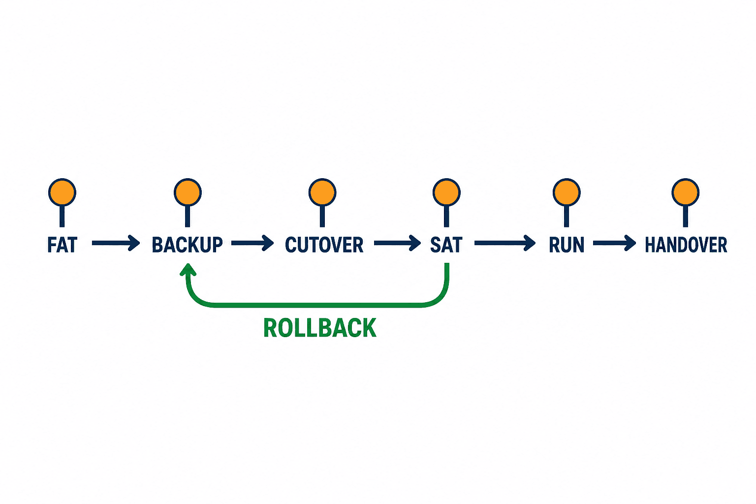
A VFD replacement succeeds or fails in the shutdown window. Create time gates and continuation criteria as well as a schedule. Before Go, close critical FAT findings; reconcile drawings; obtain existing VFD, PLC, and HMI backups; review the old/new parameter mapping; stage tools, terminals, cables, spares, resistor, and network card; name production, quality, safety, and vendor decision owners; and prove rollback fits inside the remaining window.
Pre-agree rollback triggers such as unstable communication by a time gate, unacceptable current or vibration, failed safety validation, or failed quality checks. Repeatedly deciding to “try one more thing” can consume the time needed to restore the previous system.
Retain the old hardware, tagged cables, terminal photos, parameters, software versions, and change notes until rollback is no longer required. Review trends at the first shift, 24 hours, and one week as suitable project examples; actual periods depend on process risk.
Step 11: make backups, spares, and handover contractual deliverables
The handover package should include as-built electrical, terminal, and network drawings; the native VFD parameter set and a human-readable difference report; buildable PLC/HMI/SCADA projects; firmware and device-description files; safety calculations and validation; FAT/SAT records; motor, braking, thermal, and harmonic studies; compatible spares and storage conditions; actionable fault guidance; restore and replacement instructions; license ownership; and support contacts.
Accept a backup only after it is restored to a spare drive or suitable test environment and reproduces communication and control behavior. Keep credentials out of article text and ordinary shared folders and follow the company’s secrets-management process.
Site survey, panel execution, and commissioning stages
A useful survey has both shutdown and running windows. During shutdown, inspect terminals, cables, shielding, earthing, enclosure space, cooling, and component condition. During operation, capture the events around starts, material entry, grade changes, cleaning, jams, and stops—not just averages. Link photographs to equipment tags and mark discrepancies on drawings.
Panel thermal design must include drive losses, adjacent devices, clogged filters, stopped air conditioning, sun exposure, and the factory’s hot operating period. Document input/output contactor sequences, bypass states, multi-motor or mains-transfer arrangements, because they may require protection and interlocks different from a one-drive/one-motor system.
Review parameters by functional groups: motor model and tuning; limits and resonance bands; ramps and braking; command ownership; protection; communication fallback; and safety. Record the reason for a critical default value as well as every changed value. Sign and retain FAT, SAT, and final differences. Auto-tuning also requires a method statement: determine whether rotation is allowed, how the brake is handled, and which people or equipment could be exposed.
Commissioning should progress through explicit stages: de-energized inspection; control power only; main power with output inhibited; safe low-speed rotation; no-load speed range; partial load; agreed worst load; and automatic production. Each stage has an acceptance gate. When a fault appears, log hypothesis, single change, and result so that the cause is reproducible.
As a recommended stabilization-window example, review the first 30 days; the actual duration and review points must be set from equipment and process risk. During the agreed window, review drive faults, current, speed, DC voltage, motor and panel temperature, vibration, communication errors, production, quality, and downtime across relevant shifts and products. Normalize energy results for weather, throughput, and setpoints. At the end of the agreed window, reissue the final parameters, drawings, and operating procedures and explicitly retire temporary versions.
Thailand investment and BOI information
Thailand’s BOI publishes a current Smart and Sustainable Industry page and a release covering investment applications in the first half of 2026. Eligibility, timing, investment thresholds, technical criteria, and treatment of an existing operation are project-specific. This article does not promise BOI eligibility, incentives, or approval.
If a VFD program is part of an investment proposal, separate and evidence energy, digitalization, safety, capacity, and quality benefits. Confirm the current rules with BOI or an appropriately qualified adviser before applying. A quotation marked “BOI-ready” is not proof of eligibility.
Frequently asked questions
Is matching the existing kW sufficient for a VFD retrofit?
No. Match current, overload duty, supply, ambient conditions, motor insulation, cable length, communication, and safety. A legacy drive’s years of service do not prove compatibility with a new switching and control architecture.
What information should an inverter-selection RFP provide first?
Provide motor nameplates; load and speed profiles; starts, stops and ramps; supply and transformer data; cable length; enclosure temperature; PLC/communication; and safety requirements. Attach an owner and due date to any unknown.
Is an insulation-resistance test enough to prove motor compatibility?
No. Also assess inverter-duty limits, terminal peak voltage, low-speed cooling, bearing current, resonance, sensors, and manufacturer restrictions.
Where is the boundary between inverter FAT and SAT?
FAT should front-load drawings, logic, communication, abnormal behavior, safety functions, and restore tests. SAT verifies installation, the real motor and load, site power, process integration, and stop performance. If a test is repeated, define the different purpose and condition.
Does STO eliminate the need for a main contactor?
There is no universal answer. Decide from applicable safety requirements, electrical isolation for maintenance, failure behavior, drive instructions, and local rules. STO is not a disconnecting device or mechanical brake.
How much energy will a VFD save?
No fixed percentage is defensible without measurements. DOE guidance notes that VFDs are not appropriate for all applications and savings depend on the load curve, speed, runtime, existing control, and system head. Compare normalized energy per unit of production under equivalent conditions.
Conclusion: procure a recoverable system, not a drive component
Successful inverter control starts with load, duty, and motor compatibility, then integrates braking energy, harmonics, EMC, earthing, safety, and the PLC parameter contract. FAT/SAT must produce evidence, while cutover gates, rollback, tested backups, spares, and training make recovery possible after handover.
Even if the VFD scope or RFP detail for your Thailand factory is not final, existing drawings, motor nameplates, and operating trends provide a practical starting point. Contact TOMAS TECH to discuss how to divide responsibilities across panels, PLC integration, safety, site work, and commissioning.
References
- IEC 61800-3:2022 — EMC requirements
- IEC 61800-5-1:2022 — Electrical, thermal and energy safety
- IEC 61800-5-2:2016 — Functional safety
- ISO 13849-1:2023
- NIST SP 800-82 Rev.3
- U.S. DOE Motor and Drive System Sourcebook
- ABB Guide to Harmonics with AC Drives
- Thailand BOI — Smart and Sustainable Industry
- Thailand BOI — First-half 2026 investment applications


