


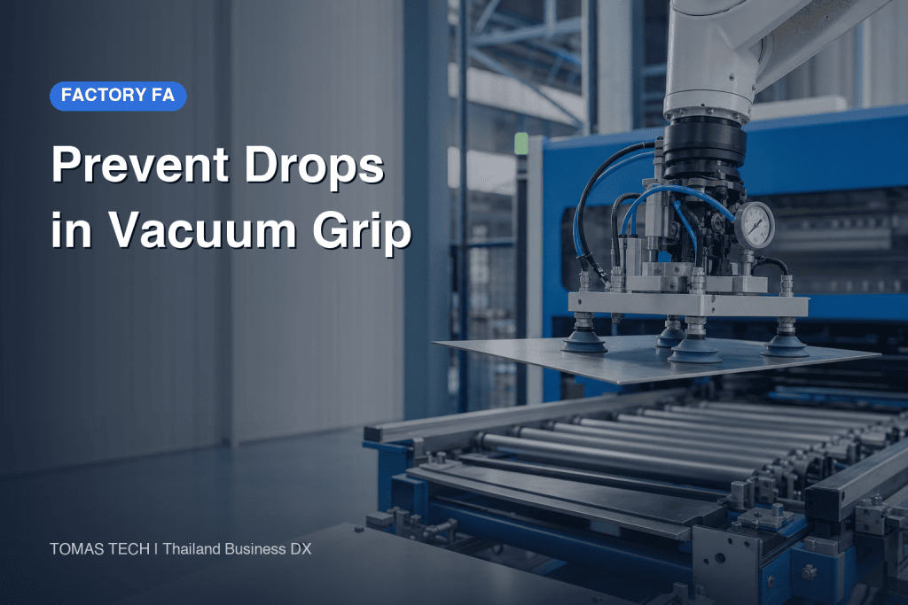
Preventing a dropped workpiece in a vacuum handling cell takes more than increasing a cup’s holding force. Air can leak between cup and workpiece during travel, plant air pressure can fall, power can fail, a sensor message can disappear, or a robot can stop in mid-path. For each event, the design must answer where the workpiece stays and where it could fall. This guide is for teams buying or modifying vacuum handling equipment in Thai factories. It covers fault modes, monitoring limits, stopping and receiving a part, restart rules, and RFP/FAT/SAT acceptance. For material and geometry choices, see our existing vacuum suction cup selection guide.
Four connected layers: detect, stop, catch and recover
First, detect a missed pickup or weakening hold. Second, decide how robot or transfer axes decelerate and stop after a fault is detected. Third, provide a way to keep the workpiece away from people and critical equipment if vacuum decays even after motion stops. Fourth, prevent automatic restart before the part is recovered and the cause checked. Linking all four prevents one missed pickup from turning into an equipment incident.
A product claim such as “holds vacuum during power loss” or “prevents sudden drop” describes a feature under particular circuit and supply conditions. It does not promise that every workpiece can remain suspended indefinitely. SMC’s vacuum equipment precautions explicitly warn that power or air trouble may lower vacuum, leading to dropped parts, injury or machine damage. Start from a whole-machine risk assessment and combine temporary retention with a layout that prevents a falling part from reaching a hazardous place. The presence of an ordinary process vacuum switch alone does not establish a protective safety function.
Separate fault modes before designing a response
If every event is called “suction failure,” suppliers will test different things and acceptance will become ambiguous. Divide the cycle into before pickup, just after lift, travel, stopped state and release. For each stage, document part location, motion, likely fall zone and whether a person can enter below it. A stop command does not instantly end motion; a sudden loss of grip may release the workpiece before the robot stops. Record not only weight but sharp edges, breakability, temperature, liquid or chemical contamination, and consequences for surrounding machines and products.
| Fault mode | Site example | First signals | Design decision |
|---|---|---|---|
| Missed pickup | Cup overhangs an edge or part absent | Vacuum build-up and part present | Inhibit motion, limited retry, reject |
| Slow build-up | Leak or blocked filter | Time to vacuum threshold | Timeout and stop position |
| In-motion leak | Oil, warp, paper variation | Pressure change close to cup | Slowdown, nearby receiver, fall zone |
| Low plant air | Concurrent users or pipe fault | Supply pressure and vacuum | Holding margin, stop, no restart |
| Power/control loss | Outage or I/O disconnect | Power, link and valve states | Unpowered valve position, catch |
| Emergency stop | Robot stops on path | Stop signal and vacuum trend | Stop pose and recovery |
| Failed release | Part remains on cup | Part present after release | Prevent the next pickup, manual removal |
Near the pickup location, a fall of a few centimetres may be captured by a small tray. Mid-swing, the same workpiece may be over a walkway or another machine. Overlay the path and potential fall footprint on plan and side views. The position of a person during normal production is different from the position during changeover, cleaning or recovery. Evaluate door and guard states in each mode. This mapping is a design input before any cup part number is chosen.
Diagnose leakage on real parts: interface, cup or circuit
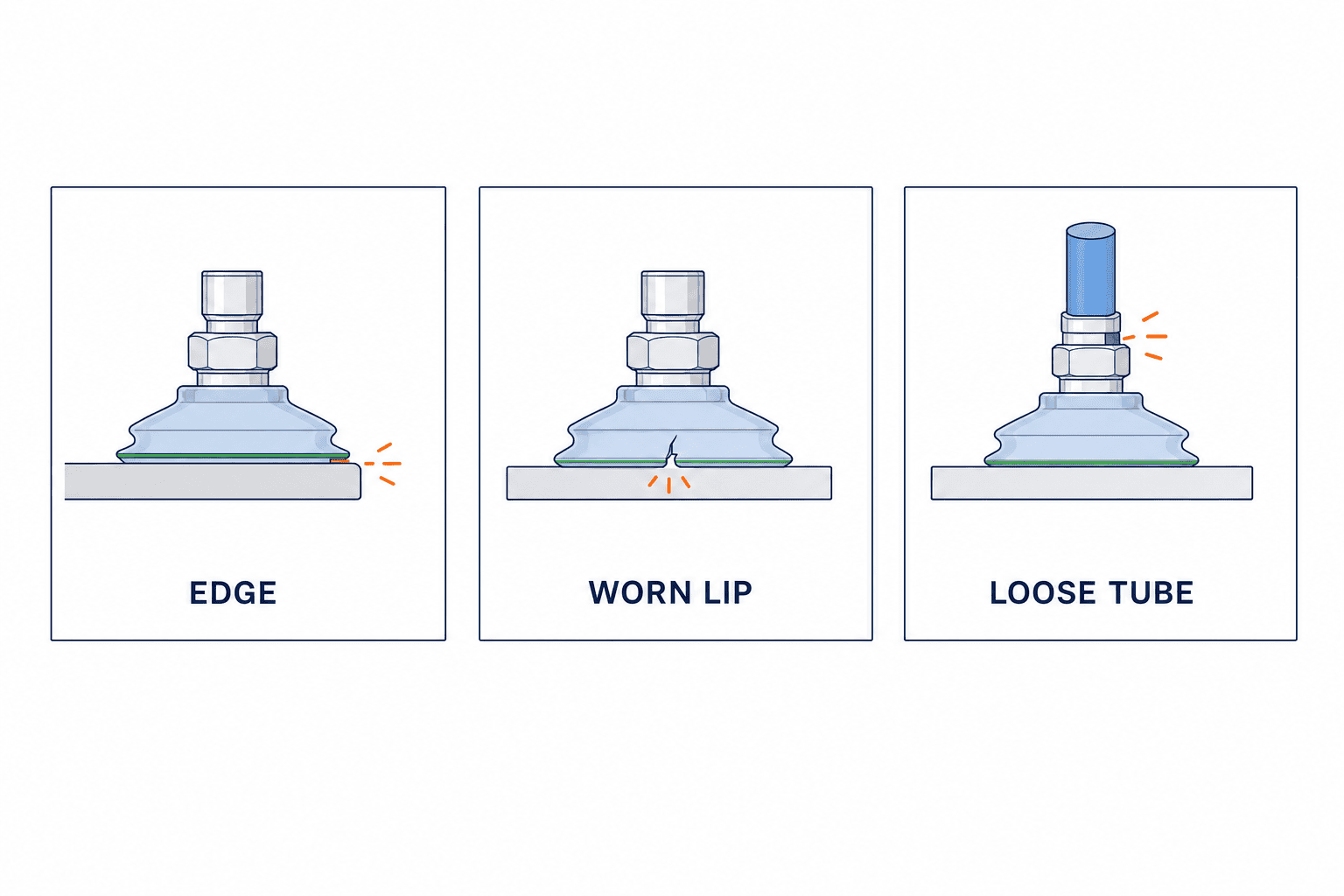
Holes, grooves, bow or paper dust admit air at the workpiece interface. A worn or cracked lip can make build-up slower over time on the same workpiece. A loose fitting, kinked hose or blocked filter can affect several products at once. Replacing all of this with a larger vacuum source may increase air use and hide the fault. Festo’s vacuum technology guide distinguishes leaky systems such as rough or porous workpieces and calls for measuring leakage flow when sizing a source.
Prepare a low-leakage reference part, an actual problem lot and a deliberately shifted pickup condition. Measure pressure near the cups and at the source, build-up time and decay during holding. If vacuum still builds slowly or decays when the cup inlet is properly sealed, or when a low-leakage reference part makes a full seal, investigate the circuit; deterioration only on one surface points toward the interface. An open, uncovered cup normally lowers vacuum and cannot diagnose a circuit leak by itself. A pressure sensor on a common header can miss one raised cup out of four. Test individual branches or deliberately open the weakest branch to see whether the others retain enough vacuum.
Determine monitoring thresholds from two stages of real-part tests
Do not copy the generator’s maximum vacuum into a “vacuum OK” setting. Measure complete pickup-to-release traces using the worst real surface, lowest allowed supply pressure, a cup representing end-of-service condition and maximum acceleration. Then separate permission to begin motion from permission to continue motion. Startup requires enough vacuum within a specified time. During travel, degrading vacuum must be recognized early enough to stop or retreat before a dangerous position. No single kPa value applies to every workpiece, sensor location and response time.
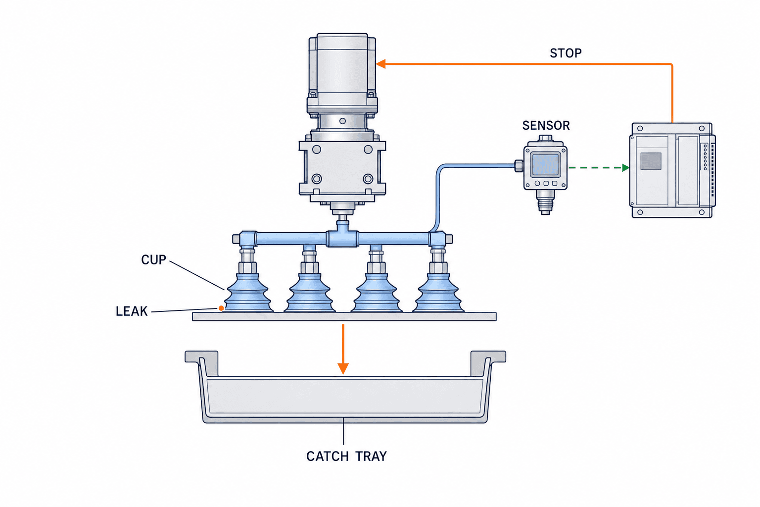
A switch at the generator outlet may not represent the contact face at the end of a long hose. Schmalz’s VSi-HD product information describes mounting close to a cup and leakage/part monitoring. Measure sensor location effects, pipe volume, sampling period, communication latency, PLC scan and robot stopping time together. Pressure crossing a limit is not the same instant as a stopped robot. Draw the positions reachable between a real leak and completed stop.
Lowering the alarm threshold reduces nuisance stops but may permit weak grips. Setting it too high may stop the line on harmless surface variation. Compare the distributions of stable grips and observed slip or release. If they cannot be separated reliably, do not call a threshold change a solution. Return to the interface, circuit, part-present sensing, speed or handling orientation. SMC’s general selection guide treats suction verification, switch setting, leakage and response time as distinct topics.
Add independent information when vacuum alone is ambiguous
A cup can seal against a fixture and show good vacuum without carrying a part. A porous part can be held while the absolute vacuum level remains modest. Where presence matters, use optical, distance, contact or receiver-side confirmation as appropriate. When signals disagree, do not assume the part is present: stop in a defined safe position and display the reason. Test dirty sensors, cable breaks and communication loss. Separate ordinary process monitoring from any protective function required by the whole-machine risk assessment.
Describe the path from fault input to stop as states
“Stop on vacuum fault” leaves crucial behavior to the programmer. Define at least idle, suction start, grip confirmation, transport, release, fault stop and recovery hold. Transport must not begin without grip confirmation. On loss of hold during transport, inhibit the next dangerous rise or swing and command the tested slowdown, stop or move to a safe receiver. Recovery hold must not automatically restart. Put inputs, action and next state into a table.
| Current state | Condition | Command | Next state |
|---|---|---|---|
| Suction start | Grip confirmed within time | Permit travel; log time and vacuum | Transport |
| Suction start | Timeout or no workpiece | Inhibit lift; optional limited retry | Fault stop |
| Transport | Vacuum or supply pressure low | Block hazard path, execute defined stop | Fault stop |
| Transport | E-stop or loss of power | Use defined valve state and physical receiver | Recovery hold |
| Release | Part remains detected | Inhibit next pickup | Fault stop |
| Recovery hold | Person confirms cause and location | Recover, inspect, home as required | Idle |
Moving to a receiver is an option only when measured retention time allows it. With a fast leak, extra movement may increase risk; stopping in place can be preferable if a catch is underneath. Choose the response per fault from the fall footprint and measured timing. A circuit that stops drives but opens the vacuum valve when power disappears can release a part at the instant of emergency stop. Read the electrical and pneumatic schematics together, including each valve’s unpowered position.
Where to place a physical catch or guide
Where the vacuum circuit cannot prevent a hazardous fall, design a tray, chute, guide or enclosure that keeps the part away from people and important equipment. A catch is not simply “somewhere below.” Decide whether it follows the path continuously or covers the risky swing, whether a corner impact can bounce out and whether a brittle part may scatter fragments. If the catch must be removed for cleaning, define an interlock or clear procedure that prevents operation without it.
SMC’s general guide discusses auxiliary drop-prevention guides, while warning that a guide that pushes on the workpiece can transfer load abruptly to the cup when removed. The whole-machine risk assessment determines coverage and access. Mechanical clamps, side supports or a path that avoids an exposed gravity drop also deserve comparison. For the choice among gripping principles, see our robot hand and gripper guide.
Power-off retention: state exactly what a check valve can protect
Non-return valves, reservoirs, normally-open or normally-closed valves and redundant sources are candidates for extending retention during a fault. A check valve controls flow in its designed circuit; it cannot remove leakage between cup and workpiece. Piab’s piSAFE VSV is described as a non-return unit that retains vacuum on system or power failure in a sealed application. Do not carry that conditionless into a porous carton or oil-wetted sheet.
SMC’s ZKJ page highlights an N.O. supply valve intended to prevent sudden drop when power is lost. A separate SMC ejector specification explicitly makes a power-off hold conditional on supply pressure remaining available. Different product configurations behave differently. An RFP should distinguish what functions without electrical power and what still requires factory air. Test electrical loss only, air loss only, both lost, and communication loss only on actual parts.
Specify required retention based on the time needed to reach a receiver or isolate the equipment, not simply “until someone arrives.” If the part cannot remain suspended that long, assess whether a catch makes its fall acceptable. Record pressure-decay traces with difficult parts and an end-of-service cup at several stop locations. Avoid a bare “holds on power loss” acceptance statement without surface, supply and duration conditions.
Prevent one uncovered cup from collapsing a common manifold
With four pickup points, one cup crossing an edge or hole can admit air into the common header and weaken the other three. SMC’s precautions warn that when multiple cups connect to one ejector, one released workpiece can cause others to release. Schmalz’s valve guide explains isolating uncovered cups or restricting branch flow. Its presence-operated sensing valve does not protect a partly covered cup.
Specify a single-point-missing condition as well as full-load lifting. At FAT and SAT, open one branch at a time, use the smallest workpiece that leaves points uncovered and test with a dirty filter condition where appropriate. Conduct fault injection with a temporary catch and no one in the fall zone. Branch check valves or restrictors can also slow pickup or release and complicate cleaning; measure those side effects rather than assuming every added device is free of tradeoffs.
Keep alternative grips and path changes on the table
For an unsealable bag, porous stock, oily sliding face or heat-softened part, a clamp, side support, dedicated fixture or different orientation may be better than adding more vacuum hardware. This is an engineering branch based on risk and maintenance cost. Changing a path from crossing a walkway to one above a fixed receiver can alter required hold time and fall footprint. If a clamp would damage the part, compare a path-side catch instead.
Compare alternatives on workpiece damage, post-failure pose, cycle, cleaning, spare parts and changeover time, not a single maximum-force rating. In a mixed-product cell with tool exchange, failed electrical or air connection at the changer is another fault mode. Require confirmation that the tool is fully seated before permitting a lift. Keeping the same fault and acceptance table across options allows fair comparison of supplier proposals.
Verify stopping distance and retention on one time axis
To know whether the robot can stop before release, put leak onset, pressure change at the measuring point, PLC recognition, deceleration start and full stop on one timeline. Compare retention and stopping time on the same part and supply condition. Neither number alone describes margin. A robot that stops successfully high above a walkway may still leave a workpiece in a hazardous position.
Stopping distance depends on current pose, axis speeds, payload, brake method and controller settings, not only a headline top speed. Require the supplier to state the measured conditions and worst location in the hazardous segment. Fault injection should use a temporary receiver and controlled access; start with a dummy part if necessary. Catch length must cover where the part may travel between fault recognition and actual stop, not just the planned production path.
For retention tests, record post-stop pressure decay using actual parts, comparing new and near-replacement cups. With a check valve, measure upstream and cup-side pressure separately: upstream isolation is not proof that the part remains held. A leaky workpiece may vary by lot and humidity, so retain the shortest observed result for each defined condition, not only an average. If the design safely catches a dropped part, proving it stays within the receiver may be more useful than extending suspended hold. The machine risk assessment and measured traces determine which approach is appropriate.
Write testable drop-prevention requirements into the RFP
“Vacuum pads with safety measures” is not comparable. Provide difficult surface samples, forbidden fall zones, operator and maintenance locations, supply conditions and the handling path as well as dimensions and mass. Ask each bidder for a fault-mode table, sensor locations, threshold-setting method, stop behavior, catch drawings and test plan. Agree numerical criteria after preliminary part tests. Do not promise an unmeasured safety performance number.
| RFP item | Evidence from supplier | Buyer check |
|---|---|---|
| Parts and path | Worst samples, poses, fall-zone drawing | Walkway, machinery and service area included? |
| Monitoring | Sensor location, traces, response/communication time | Threshold based on real parts? |
| Stopping | State chart, unpowered valve states, braking | Distance from leak to stop considered? |
| Catch/alternative | Receiver drawing, fixing and grip comparison | Part and fragments contained? |
| Recovery | Retrieval, cleaning, cause check and reset authority | Automatic restart excluded? |
| Acceptance | FAT/SAT method, forms and agreed values | Fault injection and site conditions included? |
Compare pneumatic diagrams and power-loss states, not simply the number of valves and tanks. A device may operate without electricity only while plant air remains available. Include who inspects cups, filters and pressure sensors, and how often. A low installed price can hide repeated manual retrieval and stoppage. Providing measured plant air variation and physical samples with the RFP gives bidders common assumptions.
FAT: inject faults and retain traces and final part position
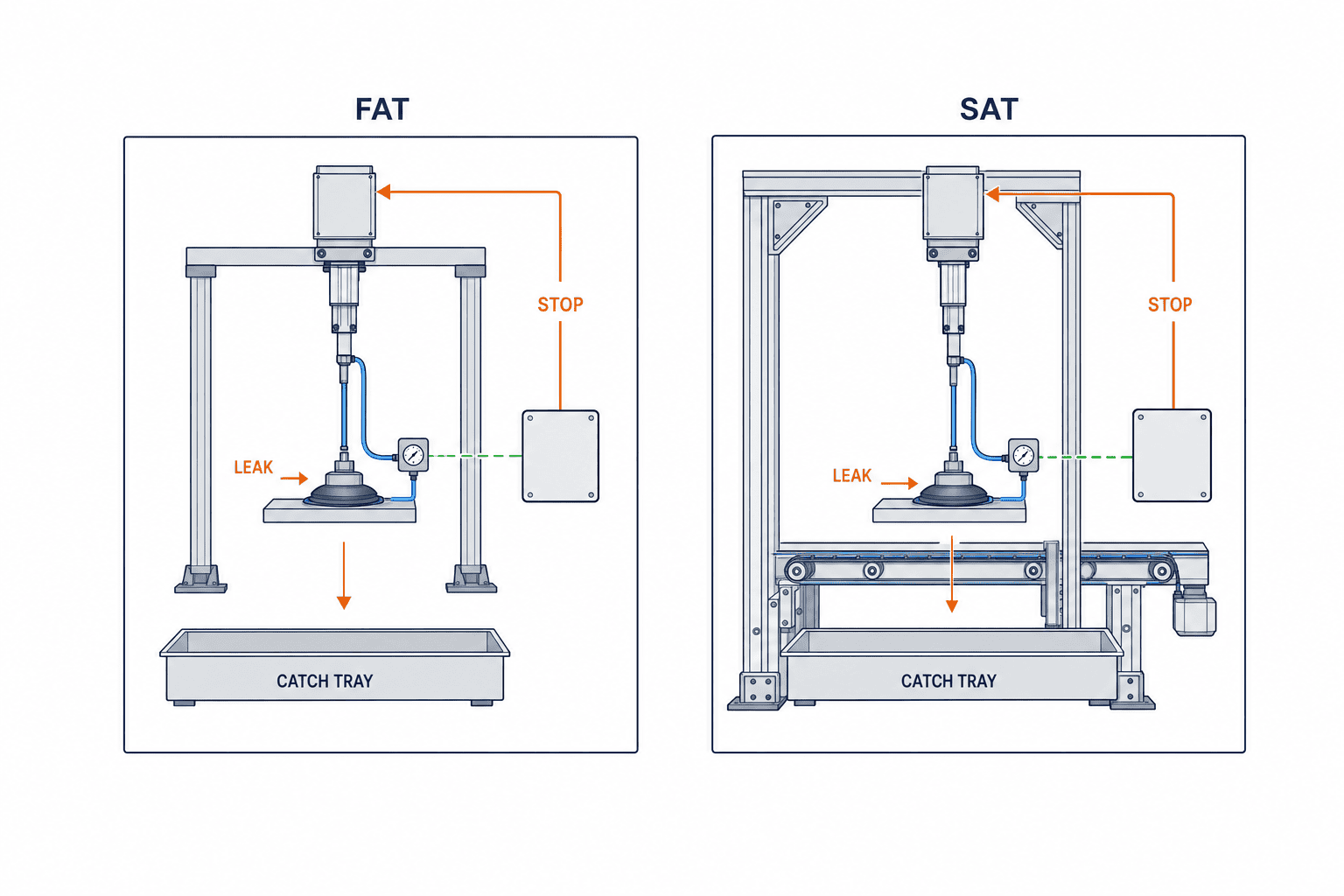
At the supplier’s site, review drawings, parts lists, pneumatic circuit, PLC state chart, handling path and catches. Test more than normal pickups: missing part, partially covered cup, leakage, low air, sensor wire break, power loss, communication loss, emergency stop and failed release. Plan safe fault injection with a temporary receiver and controlled access so people, parts and equipment are protected. Agree beforehand which tests can be performed.
For every case, use one record form for part number and lot, cup service state, air pressure, sensor location, vacuum trace, stop-signal time, stopping distance, final part location and recovery steps. Splitting the delay from leak to sensor decision and the delay from decision to robot stop shows which design element needs improvement. “Zero drops” says little if the test never raised a part to the dangerous location. Specify both difficult samples and fault positions along the path.
SAT: repeat with actual Thai-plant piping, loads and lots
Replace bench conditions with installed pipe length, fittings, supply pressure, simultaneous air users, dust, temperature and production lots. If the FAT threshold causes frequent SAT stops, investigate surface and circuit differences before loosening it. Lowering a threshold solely to keep the line running can reduce holding margin. Record changes, retest affected cases and identify an approver.
Inspect the permanent receiver and guards in their installed condition, not only the FAT temporary fixture. Check whether cleaning removes the catch, whether automatic operation is possible without it, and whether retrieval requires reaching into a hazard. For power-loss tests, distinguish electricity only, air only, both and communication only. If site constraints prevent a test, mark it unperformed with reason, residual risk and planned date; do not silently count it as passed. FAT passing does not replace verification in the plant.
| Test | FAT record | Additional SAT conditions |
|---|---|---|
| Normal transfer | Part, vacuum trace, stop margin | Real cycle, lots, concurrent air users |
| One-point leak | Branch opened, remaining vacuum and part pose | Actual pipe, smallest part, dust |
| Power/air loss | Valve state, retention, how part reaches catch | Site supply, distribution and stop pose |
| Sensor fault | Broken-wire/link signal and stop | Installed PLC and network wiring |
| Restart | Retrieval, inspection, reset order | Plant staff execute the procedure |
Recovery: handle the fallen part separately from the cause
Resetting a fault without investigation can recreate the drop at the same point. First isolate people and machine from the stopped area and locate the workpiece: cup, receiver, floor or inside another machine. Quality and maintenance rules then decide whether it can be reintroduced and whether fragments or liquid entered the vacuum circuit. Inspect cup lip, hose, fittings, filter, sensor and supply pressure. Use slow, limited movement to confirm grip and location before normal running. If robot origin or part position is unknown, prohibit an automatic next step.
Log time, product, lot, robot pose, commanded move, pressure trace, first fault signal, stop distance, final part location, replaced items and person authorizing restart. Otherwise repeated faults after a cup swap cannot be traced to surface or circuit. Count missed picks, in-motion pressure losses, outages and failed releases separately. A lot-specific pattern suggests surface investigation; a branch-specific pattern suggests piping or a cup; gradual increase suggests wear or dirt. Keep suspected and confirmed causes separate in the record.
Examples: sheet metal, carton and film need different controls
With sheet metal lifted from above, oil can increase lateral sliding during a swing. Vacuum pressure may remain acceptable even while position changes, so pressure alone may be insufficient. Test a position check, motion limit and catch. With cartons, paper grade and folds drive leakage variation; source flow, isolation of uncovered cups and build-up monitoring matter. Use the smallest carton as a fault sample if it exposes a branch. With film, test wrinkles, double pick and failed release. Strong blow-off can launch a light film, so verify both part absence at the cup and correct location at the receiver.
These are fault-mode examples, not universal prescriptions by material name. Surface treatment, mass, geometry and infeed change the result. When a new product is introduced, do not automatically inherit a previous FAT/SAT result. Reassess differences in contact face, path and fall zone and test what changed.
Frequently asked questions
Is a check valve sufficient to prevent a vacuum-grip drop?
Not necessarily. It can limit reverse flow in the designed circuit but cannot seal the interface between cup and part. Measure pressure decay after power and air loss with the most difficult workpiece. If suspension cannot be maintained, add a physical receiver, isolate the hazard area or change handling orientation.
What kPa threshold should the vacuum sensor use?
There is no universal value. Measure vacuum traces near the cup with difficult parts, minimum supply pressure and maximum motion, then set separate rules for starting, continuing and stopping. Include sensor, PLC and robot response delays when mapping possible drop locations. If vacuum alone cannot distinguish good from dangerous, change sensing or grip design.
Is equipment advertised to retain a part after power loss safe by itself?
It depends on the product circuit, remaining air supply and workpiece leakage. Some designs assume factory air is maintained; others assume a sealed workpiece. Test electricity loss, air loss and both, and evaluate the catch and access zones for the whole machine.
What should FAT and SAT prove about drops?
FAT injects defined faults and records pressure traces, signals, stopping distance, final part position and recovery. SAT repeats under installed piping, air loads and real lots, and inspects the permanently fixed catch and service arrangement. Mark any unperformed fault test explicitly with its follow-up.
The central specification is where the part goes when something fails
Preventing drops requires one specification linking fault type, detection time, stopping distance, physical receiver and restart process. Check valves and precise sensors can be useful, but effectiveness depends on sealing, supply and sensor position. State fault modes and fall zones in the RFP, and capture actual traces and final part positions in FAT/SAT. That turns a vague “safety measures included” line into testable acceptance.
If your Thai plant is planning a vacuum transfer cell or investigating dropped workpieces, contact TOMAS TECH with actual parts, handling path, air and electrical diagrams, and existing fault records. Fault modes and acceptance cases can be defined during the RFP stage.


