


The key to selecting and commissioning a steam flow meter is to first decide what to measure, in what units, and over what operating range—before searching for a model that fits the pipe diameter. In main steam lines and process-specific piping in Thai factories, low flow during startup, load fluctuations, pressure variations, wet steam, and limited straight pipe lengths often pose simultaneous challenges. This article organizes the comparison of flow meter types, density compensation, piping work, OT integration, and FAT/SAT acceptance criteria in an order usable as procurement specifications.
Before Introducing a Steam Flow Meter, Define the “Measurement Objective” in One Sentence
First, decide whether the primary objective is to “monitor total boiler output,” “allocate steam consumption by building,” or “compare startup and steady operation of a single drying process.” Even within the same factory, different objectives require different measurement points, integration intervals, accuracy, and communication destinations. Confusing total boiler output with process-specific consumption often leads to misunderstandings that flow meter faults cause discrepancies in the steam balance, which actually include branch-offs, pressure reductions, venting, condensation, and returns. Mark the measurement boundaries on the piping schematic with colors and finalize which valves and bypasses fall within the boundary before ordering.
Steam “quantity” distinguishes between volumetric flow and mass flow. For manufacturing cost, line-specific unit consumption, and heat balance, mass flow in kg/h and cumulative mass in kg are usually specified. Sensors that measure only velocity or volume do not account for steam density changes due to pressure. Spirax Sarco’s instrumentation guide explains that steam flow meters without built-in density compensation require additional pressure or temperature measurements. Source: Spirax Sarco “Instrumentation”
Add operational considerations to the objective sentence. For example: “The equipment team will weekly check deviations from the baseline after product changeover by viewing hourly kg/h and daily cumulative kg for Process A.” Once this is decided, it becomes clear that not just display but also saving operation signals, product types, shifts, and steam pressure on the same time axis is necessary. The budget request should state “what will be changed after measurement.” Measurement alone should not be considered energy saving; repair of steam leaks, resetting, and reduction of unnecessary warm-up should be separately evaluated as implementation results.
Separate Roles from Boiler Monitoring and Trap Monitoring
A steam flow meter quantifies flow passing through a pipe cross-section. Boiler remote monitoring mainly tracks equipment status such as combustion, feedwater, and pressure, while steam trap monitoring detects individual drainage or leakage abnormalities. Combining all three into a single “steam IoT” order can blur measurement success criteria. If trap-level anomaly detection is already under consideration, refer to Design for Wireless Steam Trap Monitoring and separate its role from main steam line mass integration. Existing Factory Flow Meter Monitoring PoC and RFP Guide is used for overall data collection design; this article focuses on steam-specific density and condensate issues.
Collect Operating Data Needed for Selection Before Maximum Values
Do not write only the nominal pipe diameter in the input sheet for model selection. Record at least the P&ID of the measurement point, pipe inner diameter and schedule, material, insulation, horizontal/vertical orientation, pipe elevation, nearby elbows, branches, pressure reducing valves, control valves, straight pipe length, inspection space, and allowable downtime. For steam, note whether saturated or superheated, normal/minimum/maximum pressure and temperature, dryness fraction measurement status, operating flow range, temporary startup flow, and annual operating hours separately. If no flow history exists, create a hypothetical range from boiler evaporation, process heat load, batch cycles, valve openings, and existing fuel/feedwater data, and present it to the manufacturer as uncertain conditions. Do not finalize model selection by falsifying estimates as measured values.
Sizing based only on maximum flow can cause normal operation to fall below the meter’s lower measurement limit. For example, selecting a large instrument based on a few minutes of warm-up peak may obscure usage during the rest of the time, failing the installation objective. Conversely, selecting too small a meter causes pressure loss and velocity restrictions. Request quotes listing minimum continuous, normal, maximum continuous, and short-term peak flows separately, and have vendors return measurement ranges, error conditions, and pressure loss for each point. Spirax Sarco’s installation guidelines also require selecting flow meters based on capacity, not just line diameter. Source: Spirax Sarco “Installation”
A single daily representative value hides load valleys. Separate stop, warm-up, steady, cleaning, and standby states with time granularity matching 30 minutes or process cycles. If low flow is important for management decisions, verify not just the catalog’s single turndown ratio but “the error band applicable at that low flow under actual steam pressure, temperature, and piping conditions.” If factory data is insufficient, consider preliminary trial measurement. Selection order starts from the load you want to know operationally, not the purchased instrument’s specifications.
Compare Steam Flowmeter Types Based on Steam Condition and Piping Requirements
Candidates include vortex, differential pressure, and variable area types. The type name alone does not determine superiority. Spirax Sarco summarizes the advantages and limitations of each steam flowmeter type, emphasizing that proper application suitability is the prerequisite for accurate and continuous measurement. Source: Spirax Sarco “Types of Steam Flowmeter”
| Comparison Item | When Considering Vortex Type | When Considering Differential Pressure Type | When Considering Integral Variable Area Type |
|---|---|---|---|
| Points to Confirm First | Minimum flow, vibration, straight pipe length, steam dryness | Primary element such as orifice, differential pressure transmitter, impulse piping, pressure loss | Applicable steam condition, pipe size, flow direction, actual flow range |
| Mass Flow Calculation | Check built-in or external density compensation specifications | Confirm calculation specifications including differential pressure and density | Confirm product-specific correction and output specifications |
| Easily Overlooked During Installation | Upstream and downstream straight pipe lengths, distance from pressure reducing valve | Protection and maintenance of impulse piping, condensation conditions | Installation orientation, maintenance space, bypass |
| Items to Specify in Purchase Order | Lower and upper limits and accuracy under operating conditions | Overall system accuracy including primary element and calculation | Proof of compatibility with target steam, direction, and range |
Vortex flowmeters are widely considered for steam applications but should not be chosen solely because they have “no moving parts.” Emerson’s vortex flowmeters for utilities list steam as an applicable fluid and highlight the advantage of designs that do not require impulse piping. However, individual manuals caution about straight pipe requirements, vibration, avoiding installation that traps condensate, and the placement of pressure and temperature sensors. Since conditions vary by product series, do not apply general straight pipe length values from other manufacturers or different models. Source: Emerson “Rosemount 8600 Vortex Flow Meters” / Emerson “Rosemount 8800D Reference Manual”
For differential pressure types, the measurement chain includes not only the primary element such as an orifice but also the differential pressure transmitter, impulse piping, pressure or temperature inputs, and the calculator. Spirax Sarco’s instrumentation explanation shows the relationship of calculating mass from differential pressure and the influence of density fluctuations on readings. When estimating installation costs, also consider whether field maintenance can handle impulse piping clogging, leaks, and zero checks. Comparing only the purchase price of standalone devices often overlooks the cost of required transmitters and maintenance.
In tight installation spaces, integral variable area types marketed for “space-saving” may be candidates, but verify applicable steam, pipe size, minimum flow, and straight pipe length against the product documentation. Spirax Sarco’s TFA is an example product for saturated steam, showing typical installation with upstream separators and condensate handling. However, the straight pipe length shown is specific to the TFA and not a general rule for all types. Source: Spirax Sarco “TFA Saturated Steam Flowmeter”
Do Not Specify Electromagnetic Flowmeters Directly on Steam Mains
Do not confuse flowmeters for water or condensate with those for steam. Electromagnetic flowmeters operate on the principle of conductive liquids and are not candidates for direct use on vapor-phase steam mains. If measuring condensate return flow, confirm that the fluid is liquid phase, full pipe, and review temperature, conductivity, and piping conditions accordingly. In quotation lists, do not simply list “flowmeter” generically; specify the phase and condition measured for each line. Source: Endress+Hauser “Flow measurement for liquids, gases and steam”
Place Density Compensation and Wet Steam at the Core of Selection
Even at the same volumetric flow, steam mass changes with pressure and temperature. For saturated steam, pressure and temperature correspond, allowing configurations that use appropriate steam tables and one measured parameter to determine density. However, it is incorrect to say “one pressure input covers all steam.” Including superheated steam and operational changes, verify in specifications and tests which conditions the product supports and what compensation calculations it performs. Yokogawa provides an example of a vortex flowmeter with an internal temperature sensor calculating saturated steam mass flow, but if adopting this, confirm sensor and calculator settings by model. Source: Yokogawa “Massflow Measurement of Steam”
The notation “pressure 5 bar” is also risky. Gauge pressure (bar(g)) and absolute pressure (bar(a)) differ, and confusing them in density calculations causes systematic errors. Clearly specify units and pressure reference in purchase orders, PLC tags, displays, and acceptance test records. Fix units for totalized quantities (kg or t) and pulse output (kg/pulse) similarly. Even if displays appear correct, accidents where gateways convert values by factors of 10 or 1000 can be prevented by cross-checking configuration tables.
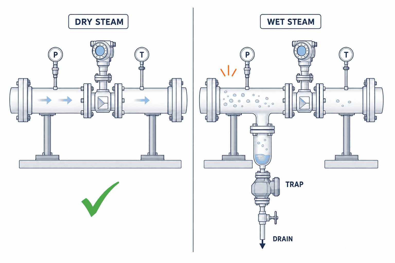
Wet steam presents a different challenge. When liquid droplets mix in the pipe, the relationship between the velocity or vortex state sensed and the desired total mass or enthalpy is no longer straightforward. Do not add “same accuracy for wet steam” to standard steam flowmeter specifications. Endress+Hauser explains that some vortex models offer options to assess wet steam quality, but this is not a standard feature for all vortex meters. For lines suspected of wet steam, first inspect separators, condensate discharge, insulation, and low-point piping design. If quantifying wetness is required, verify individual specifications of suitable models. Source: Endress+Hauser “The vortex flowmeter”
Ignoring steam dryness and looking only at flow has limits for enthalpy evaluation. Even with the same mass (kg), the effective heat input to the process varies with steam condition. Separate the purpose of flowmeter installation—whether for mass allocation between equipment or for precise heat balance—and combine pressure, temperature, and condensate measurements as needed. Confirm what inputs and assumptions manufacturers use when presenting “steam energy” values. Even if temperature and pressure are measured, uncertainty remains if dryness is not directly measured.
Pipe Design Must Prepare Conditions Upstream and Downstream of the Sensor
The most costly rework in installing a steam flow meter is discovering after purchasing the instrument that “there is insufficient straight pipe length” or “condensate accumulates at low points.” In addition to sending site photos and actual dimensions to the manufacturer, mark on the P&ID the sequence and distances of pressure reducing valves, control valves, shut-off valves, elbows, separators, drains, instruments, and downstream branches. Specify the straight pipe lengths upstream and downstream both as multiples of the pipe diameter D and in actual millimeters, then verify against the latest installation manual of the selected model. Spirax Sarco lists unobstructed straight pipe lengths upstream and downstream, steam dryness, pipe supports, and insulation as critical installation factors. Source: Spirax Sarco “Installation”
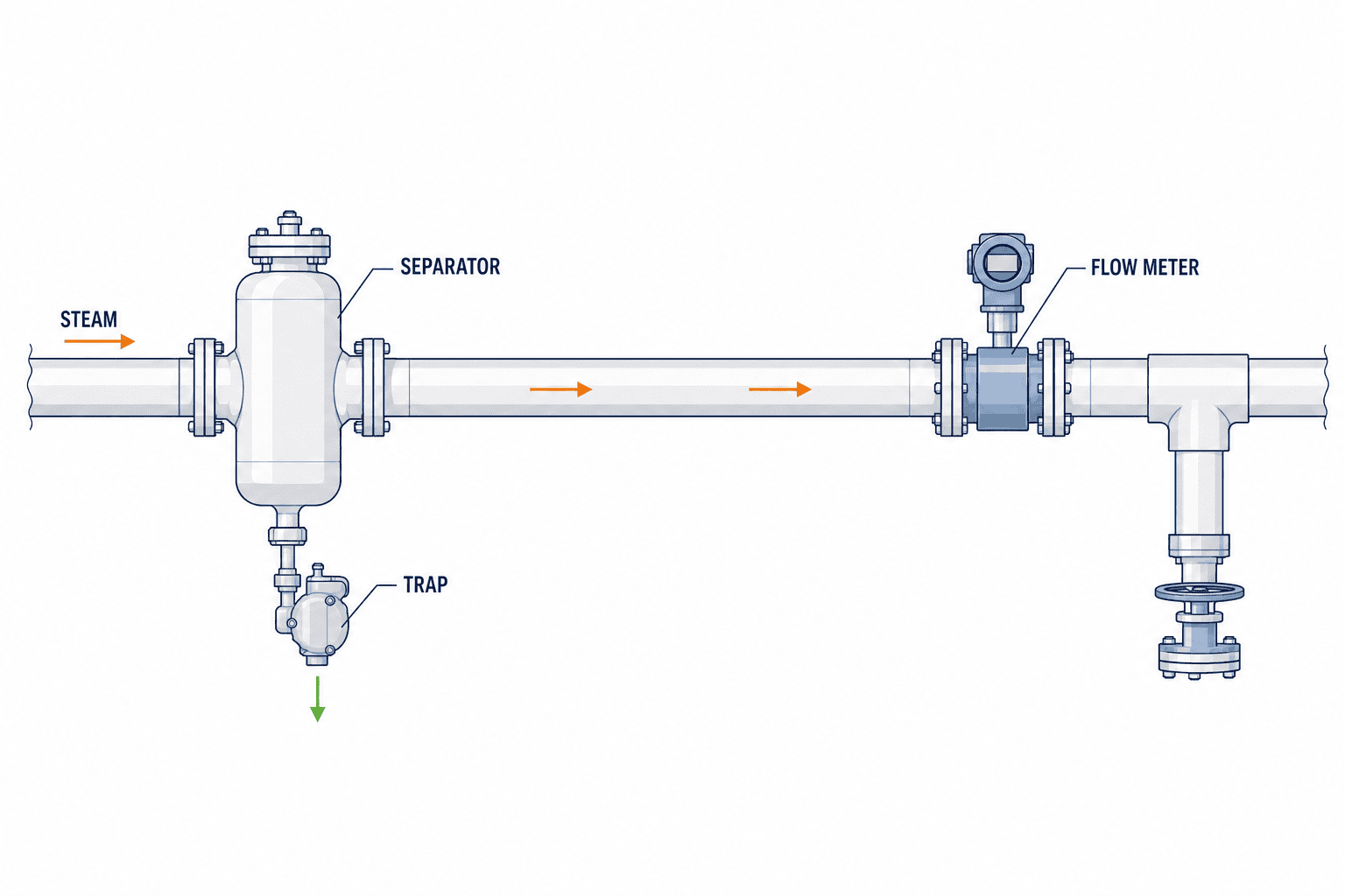
Place the separator upstream of the instrument and discharge condensate through an appropriate trap. If there are low-point drains or missing insulation, simply improving conditions immediately before the instrument will not eliminate water hammer or wet steam during startup. Support piping properly, align flange positions, and avoid imposing pipe loads on the instrument body. If pipe diameter reduction is necessary, confirm the reducer shape and location with the vendor to prevent condensate accumulation. The need and placement of strainers, bypasses, and isolation valves vary by model. Do not adopt uniform distances or screen specifications from general articles as a substitute for individual design.
Steam mains are hot and pose hazards during shutdown and opening. Field work must follow factory isolation and lockout, cooling, residual pressure confirmation, condensate discharge, work permits, and internal and local requirements related to pressure piping. The scope of supply should include spool fabrication, welding/NDT requirements, insulation restoration, instrument power supply, cable trays, network, commissioning attendance, recalibration, and spare parts. Estimates based only on sensor price cannot compare the entire construction cost.
When Straight Pipe Length Is Insufficient, Request “Proof of Exceptional Conditions”
If the instrument manufacturer proposes flow conditioners, correction factors, or installation with short straight pipe lengths, obtain justification based on upstream piping obstructions and operating range. The catalog accuracy claim of “±1%” does not guarantee performance under field conditions with insufficient straight pipe. Compare relocation to alternative measurement points, piping modifications, and load sharing among multiple instruments. Emerson’s 8800D manual distinguishes minimum installable straight pipe conditions from those required for baseline accuracy; this distinction should be confirmed in the RFP. Source: Emerson “Rosemount 8800D Reference Manual”
Include “Acceptable Instrument Set Values” in the RFP
In the request for proposal, place measurable conditions before product names. The following are minimum confirmation items.
| Item | Information Provided by Purchaser | Response from Vendor |
|---|---|---|
| Measurement Purpose | Total steam mass, allocation, process monitoring; required integration period | Proposed method and measurement boundaries |
| Steam Conditions | Saturated/superheated; normal/minimum/maximum pressure and temperature; concerns about wetness | Applicable range and exclusion conditions |
| Flow Conditions | Continuous minimum, normal, continuous maximum, short-term peak | Measurement feasibility, error, pressure loss at each point |
| Piping Conditions | Inner diameter, direction, upstream obstructions, available straight pipe length | Required length by model, additional construction, maintenance space |
| Calculation and Output | kg/h, kg, timestamp, signals, power failure recovery | Density compensation input, units, communication tag list |
| Quality Assurance | Installation, FAT, SAT, calibration certificate requirements | Drawings, setting tables, certificates, test procedures |
Always specify whether “accuracy” is expressed as a percentage of full scale or reading, and over which flow range and steam condition it applies. The same accuracy figure does not necessarily apply to the sensor alone, with the calculator, or the entire system after installation. Add “error at minimum required flow” to comparison tables and do not evaluate solely on catalog accuracy at maximum flow. Confirm calibration certificate traceability and next calibration method at the contract stage.
Total cost of ownership includes instruments, separator and drain systems, piping modifications, downtime, cables, communication devices, insulation restoration, calibration, spare parts, and maintenance. In hot and humid plants, the mounting environment and inspection access for electronics are important; do not judge outdoor installation feasibility by IP rating alone. Verify actual mounting orientation, direct sunlight, vibration, washdown water, and insulation coverage against the model’s installation manual. Record not only the selected method name but also reasons for rejecting other candidates to facilitate future expansions.
For OT/IoT Connectivity, Store Raw and Calculated Values Separately
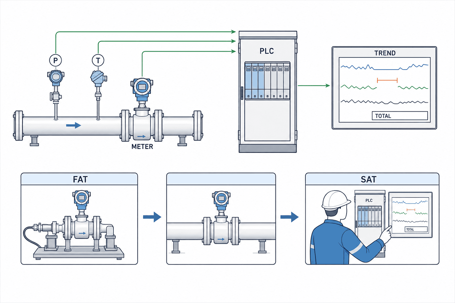
In addition to mass flow (kg/h) and totalized mass (kg), collect instrument status codes, pressure, temperature, steam condition, instantaneous volumetric flow, calculation quality, and totalizer reset history as much as the output allows. If values not provided by the instrument are estimated by the PLC, assign ownership of calculation formulas and coefficients. Choose communication methods such as 4–20 mA, pulse, or Modbus according to equipment, but tag meaning is not determined by protocol name alone. Define signal range, scaling, polarity, units, totalizer digits, overflow behavior, power failure retention, and communication loss values in the I/O list.
Time synchronization and handling of missing data affect monthly unit comparisons. For example, reading the PLC totalizer every minute and double-counting differences after communication loss inflates monthly totals. Save totalizer resets and rollovers as events, and display missing periods as missing. If interpolation is applied later, indicate on the screen that values are estimates. Implement checks comparing summed instantaneous flow with instrument totalizer values, considering sampling intervals and time shifts.
Do not immediately interpret steam flow during non-operating periods as leakage. Warm-up, standby heating, common piping demand, bypass, and measurement near zero flow affect readings. Interpret together with operation signals, valve states, process schedules, and pressure fluctuations. Anomaly detection should initially be an alert for deviation from baseline over a certain period, followed by cause investigation. Identifying individual steam trap failures from a single flow meter alone is not possible.
Decide Items to Confirm at FAT and SAT Before Contracting
At FAT (Factory Acceptance Test), verify the delivered model, size, materials, output modules, firmware, calibration certificates, and configuration sheets. Using simulated inputs or calibration equipment, confirm calculations at measurement points corresponding to minimum, normal, and maximum flow, as well as responses to changes in pressure and temperature compensation inputs. If switching between saturated and superheated steam settings is applicable, test that operation. Record ranges for 4–20 mA and pulse outputs, communication tags, units, alarms, power failure recovery, and retention of accumulated values. At SAT, check the installed piping conditions that cannot be simulated at FAT. Ordinary SAT checks do not establish the measurement error under wet-steam conditions; define a device-specific validation or reference method separately if that accuracy matters.
At SAT (Site Acceptance Test), first verify against installation drawings. Confirm actual flow direction, straight pipe length, separators and drains, pipe supports, insulation, electronics environment, flanges/impulse lines, and pressure and temperature tap locations. At no-load, normal, and high-load operating points, simultaneously record instantaneous values, pressure, temperature, incremental totals, PLC and monitoring screen units, and timestamps. If a reference flow meter cannot be installed on site, do not claim “absolute accuracy proven at SAT”; distinguish between calibration certificates and on-site consistency checks. If measurement uncertainty is large relative to the application, plan additional reference measurements or temporary mass balances.
Acceptance criteria should be more specific than simply “displayed values.” Examples include: the three specified operating points fall within the product’s applicable range; instrument display and PLC kg/h values agree within specified tolerances; no order-of-magnitude discrepancies between pulse and totalized conversions; communication interruptions are recorded as missing data; reset behavior of totals matches documentation; maintenance personnel can restore settings from backups. Tolerance values are determined at contract based on application and instrument guarantees, not by reusing generic values from articles.
Handover documents include as-built P&IDs, installation photos, tag lists, scaling tables, compensation methods, calibration certificates, FAT/SAT reports, maintenance procedures, spare parts, operation permissions, and change history. Avoid leaving only software screens so that instrument settings depend on personnel memory. Any vendor-modified coefficients must have approval and traceability. This facilitates future re-selection for flow increases or process additions.
After Installation, Evaluate “Flow Changes” and “Improvement Results” Separately
Use the first few weeks to stabilize instruments and establish baselines. Compare kg/product, kg/operating hour, and standby kg/h with product types, operating hours, production volume, steam pressure, and seasonal conditions noted. Note that unit consumption varies with product mix. Do not claim savings from simple month-to-month comparisons; compare intervals with the same product and operating conditions. If values deviate from baseline, narrow causes in order: flow meter status codes, steam pressure/temperature, separators and traps, valves and bypasses, process conditions.
In improvement activities, document measurement → hypothesis → field action → re-measurement. For example, do not conclude “leak” solely from observing high nighttime usage; check which common equipment was operating. If trap abnormalities are suspected, proceed to individual inspections. If confusing with compressed air energy savings measurement, refer to Compressed Air Flow Meter Selection as a separate design example, but do not directly apply steam density, condensation, or drain conditions.
How to Compare Steam Flow Meter Installation Costs?
Compare not only instrument unit price but also upstream separators and drain handling, piping modifications to secure required straight pipe lengths, shutdown work, insulation restoration, inputs needed for density compensation, OT connections, calibration, and periodic inspections within the same scope. If the quotation does not clearly state what is included, a cheaper instrument does not guarantee a cheaper project. Request separate presentation of fixed costs, annual costs, and shutdown impacts.
Can the Same Flow Meter Be Used for Saturated and Superheated Steam?
Even if the same product series covers both, verify temperature and pressure ranges, density compensation, seals, materials, and settings separately. Do not apply saturated steam density calculations directly to superheated steam. Specify measurement conditions on product data sheets and confirm switching and calculations at FAT.
Can Accurate Flow Measurement Be Achieved with Wet Steam?
First investigate causes of wetness and piping that allows condensate to reach the instrument. Do not expect the same accuracy from products designed for dry steam when wet steam is present. Some products support wet steam or dryness evaluation functions, but applicability and uncertainty are model-specific. After ensuring proper separators and drain discharge, confirm with the manufacturer the mass and heat accuracy required for the purpose.
Where Should the First Unit Be Installed?
For cost allocation, choose a major process branch; for overall balance, consider boiler outlet or main header. However, required dryness, straight pipe length, maintenance access, and feasibility of shutdown work take priority. Establish measurement boundaries and data usage at one point first, then expand to other branches. When installing multiple points simultaneously, unify tags, units, and totalization intervals.
Example Installation Plan: Expand from One Main Header Point to Process-Specific Measurement
It is not necessary to measure all branches factory-wide from the start. The first measurement point should meet three conditions: “shutdown can be arranged,” “straight pipe and drainage conditions are adequate,” and “there is a responsible person to use the measurement results.” For example, record time series of generation at one main header point; if load valleys and peaks are confirmed in a high steam usage process, consider installing an instrument at that process inlet next. When installing instruments at both main header and process inlet, align pressure stages and piping boundaries, and compare totals over the same time intervals. Do not immediately label differences as “leaks”; check unmeasured branches, steam venting, drains, instrument uncertainty, and timestamp offsets.
The initial single point also serves as a training ground for data use. Overlay events such as product changes, CIP, weekend standby, and boiler switching with operation logs, and have field personnel explain what flow peaks correspond to. Even if sensors show no abnormalities, incorrect definition of measurement boundaries invalidates process comparisons. Show operators the screens and confirm “what this value is used for” and “under what conditions to recheck.” Do not consider PoC success as only communication success; record at least one operational decision linked to the data.
When expanding, do not mechanically replicate the same model. Minimum flow, steam condition, upstream pressure reducing valves, and straight pipe availability differ by process. Even with the same diameter, optimal instruments may differ. However, tag rules, units, total reset and missing data handling, time synchronization, and FAT/SAT formats can be standardized. This principle of “site conditions are individual, data definitions are common” reduces the burden of rewriting aggregation logic with each equipment update.
Procedure When Shutdown Time Is Short with Existing Piping
Complete site measurements before work, and pre-fabricate spools, supports, isolation valves, separators, and instrumentation cables. If pressure piping must be cut, prepare a schedule detailing how much welding, inspection, pressure or leak testing, insulation restoration, power-up, loop testing, and warm-up can be completed within allowable shutdown time. This does not prescribe a uniform construction method. Approve inspection procedures according to the plant’s maintenance regulations, jurisdictional requirements, and contractor responsibilities. Decide contingency days and conditions for reverting to old operation in advance.
Some request “no shutdown, just clamp-on.” Confirm whether candidate instruments meet steam vapor phase conditions. Do not directly repurpose clamp-on ultrasonic meters designed for liquids on steam mains. When comparing non-intrusive options, obtain from manufacturers the steam-compatible measurement principle, applicable pressure and temperature, required piping conditions, measurement lower limits, and basis for field accuracy. Avoiding piping work is not the sole evaluation criterion. The primary question is whether the measurement can be used for the intended mass balance.
Three Common Conversion Mistakes in Data Usage
The first is pressure conversion. When the piping instrument is set to bar(g) and the calculator to bar(a), simply passing the numerical value leaves a difference equivalent to atmospheric pressure. The pressure reference must be clearly indicated at the PLC or flow calculator input point. During FAT, simulate representative low, normal, and high pressures to verify the reference conditions and results against the steam tables. If two sensors return temperature and pressure, use this to diagnose whether the data is consistent with saturated steam, but do not automatically correct for superheat or sensor errors to produce a “correct” compensation value.
The second is converting instantaneous values to cumulative totals. If receiving kg/h values every minute, simply summing all samples does not yield kg. Multiply each interval by its time width in hours and sum, handling communication interruptions and sample delays. If possible, also save the instrument’s own cumulative total and periodically reconcile it with the calculated total. However, how the instrument handles flow near zero, whether values are retained during power outages, and whether the total resets after instrument replacement depends on product settings. Confirm these rules and do not mistake differences for faults.
The third is steam consumption per unit. Even when the denominator is “number of products,” the value changes depending on product type, size, drying conditions, and the difference between good and input quantities. Listing only daily kg/unit can lead to misinterpreting changes in product mix as equipment degradation. Initially, filter by process code and operating status, then compare periods under the same conditions. If abnormal peaks remain, investigate not only flow but also pressure, valve operation, production plans, and maintenance records. The benefit of installing instruments is not adding more screens but enabling this tracking in a short time.
Summary
Selecting a steam flowmeter proceeds in the order: “measurement purpose and boundaries → actual minimum, normal, and maximum flow rates → steam condition and density compensation → installation including separators, drains, and straight pipe → data definition → FAT/SAT.” Even good instruments cannot compensate for wet steam, incorrect pressure units, or operation below the measurement range. When equipment, instrumentation, and production share the same specifications and acceptance records, flow data becomes easier to use for cost and improvement.
TOMAS TECH supports steam piping in Thai factories, assisting with measurement point selection, steam condition, and integration with existing PLCs and monitoring screens. Consultations are available even before the instrument model is decided, based on current P&ID and operating ranges. Contact us.


