


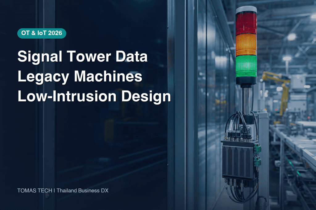
For a Thailand or ASEAN factory, signal tower data collection can be one of the least intrusive ways to observe legacy equipment. The difficult decision, however, is not which transmitter or gateway to buy. It is deciding what a lamp input proves, how it becomes a machine state, and which business decisions must still rely on production counts, work orders, calendars, alarms or operator reason codes.
This guide turns stack-light monitoring from a screen project into a testable engineering and operating design. It compares direct dry-contact capture, vendor wireless add-ons, PLC and IO-Link access, and an edge-gateway pattern. It then covers state precedence, timestamps, debounce, heartbeat, missing data, OT cybersecurity, site surveys, PoCs, RFPs, FAT/SAT and KPI governance.
1. What signal tower data can—and cannot—prove
Treat the tower as an observation point
A signal tower exposes something that machine control has chosen to indicate. Capturing a red, amber, green or buzzer input may be possible without rewriting the machine program. That makes it attractive when old and new assets coexist and a production stop for modification is difficult.
The raw fact is still only that an input was on, off or changing at a particular observed time. It does not automatically prove why the machine stopped or whether it was producing good parts. The actual electrical drawing, tower wiring, machine logic and operator work standard must be checked per machine.
| Question | Can tower data answer it alone? | Additional evidence |
|---|---|---|
| When did an input turn on or off? | Conditionally | Capture method, time source and missing-data rules |
| How long was a lamp lit or blinking? | Conditionally | Sampling, debounce and blink interpretation |
| What display state did the machine show? | Yes, after mapping | Machine-specific combination and precedence rules |
| What was the true production cycle? | No | Completion pulse, count or production record |
| Why did the machine stop? | Usually no | Alarm, operator reason and maintenance record |
| What was OEE? | No | Planned time, quantity, quality and agreed speed basis |
Calling green-lamp duration “runtime” before validation is a common source of distrust. A machine may keep green on while starved, show amber during warm-up, or turn every lamp off when control power fails. A more defensible first outcome is a documented observation model that operations and engineering can reproduce.
Keep four data layers separate
Use four distinct layers:
- Raw inputs preserve red, amber, green, buzzer, contact and communication observations.
- Normalized states apply a versioned per-machine rule to produce states such as RUN, STOP, ALARM, IDLE or UNKNOWN.
- Business events represent actions such as stop start, recovery, confirmed reason or changeover.
- KPIs combine those events with work orders, counts, quality and the planned-stop calendar.
This separation lets a team improve a rule and recalculate history without destroying the evidence. It also prevents a dashboard label from being mistaken for the raw condition.
2. Architecture choices for PATLITE monitoring and signal tower IoT

Direct dry-contact capture
A digital input module can read a safe contact or approved branch from the signal circuit. The relationship between the contact and the acquired input can be made clear, and no radio network is required. The design must still address voltage and polarity, isolation, terminal capacity, cabinet access, drawing revisions, machine warranty and the maintenance owner.
Temporary PoC wiring should not quietly become the production standard. Production deliverables should include terminal and wire identification, updated drawings, spare-channel rules, replacement instructions and evidence that a fault in the monitoring circuit cannot affect machine control or safety.
Vendor wireless add-on
PATLITE documents the WD system as collecting signal-tower input through transmitters, carrying it over a WD wireless network to a receiver or host, and logging CSV data through setup software. Its current product description presents this as a way to collect status from compatible signal towers irrespective of machine age or model. WD PRO provides contact-input and integration options, but exact compatibility, connectors and capacity must be checked for the selected models.
The WD manual describes up to 30 transmitters on one receiver network and identifies 20 as recommended in the current brochure context. Those are product-specific figures, not a universal design target. A brochure distance is likewise a reference under stated conditions, not guaranteed performance among metal machines, cabinets, walls, moving material and other radios in a Thai factory. An on-site radio survey and acceptance test remain necessary.
Wireless add-ons can reduce invasive work, but the operating model must cover transmitter power, compatibility, receiver failure domains, spares, configuration backup and radio changes. CSV export is not the same as a business KPI, and PATLITE’s visualization application is a separate host-side function.
PLC or IO-Link access
Where a PLC already contains useful state bits or alarm codes and authorized access is possible, it may provide richer context than the lamp. A mixed strategy is often sensible: towers as a common low-intrusion starting point and PLC connections for selected machines that justify deeper integration. See our PLC data collection guide for the broader interface discussion.
IO-Link is standardized as IEC 61131-9. It is point-to-point communication for sensors and actuators and supports bidirectional process, parameter and diagnostic information. It is not a fieldbus, and it should not be imposed as a requirement for every legacy tower. Use it where the device and master support it. The current released package shown by the IO-Link Community is version 1.1.5 (2025 package); the specifications and device IODDs should remain the interface source of truth.
Edge gateway for a mixed estate
An edge gateway can normalize a factory estate that combines contacts, wireless receivers, PLCs and IO-Link. Its responsibilities may include input timestamps, debounce, blink recognition, local buffering, retries, duplicate protection, heartbeat, configuration versions and authenticated upstream delivery. The boundary between edge and server logic should follow recoverability and the actual maintenance organization, not an arbitrary product diagram.
| Decision factor | Direct contact | Wireless add-on | PLC / IO-Link | Edge integration |
|---|---|---|---|---|
| Intrusion into installed equipment | Depends on approved wiring | Often lower | Depends on access and change control | Inherits the field method |
| Semantic depth | Mainly input status | Mainly tower status | Can include tags and diagnostics | Normalizes multiple sources |
| Key survey item | Drawing, isolation, cabinet work | Compatibility, radio, power | Tags, permissions, cycle, IODD | Buffering, clocks, retries, support |
| Typical fault to test | Open circuit or input fault | Radio or transmitter loss | Communication or configuration loss | Store-and-forward and duplication |
For a wider selection framework, read our legacy equipment IoT retrofit guide.
3. Build a state model for red, amber, green and buzzer combinations
Never assume universal color semantics
“Green means running, amber means waiting and red means alarm” may be a workshop hypothesis, but it is not a factory-wide truth. Meaning varies with builder, control version, retrofit history, operating mode and work standard. For each machine, collect:
- electrical drawings and tower wiring;
- control conditions for steady, blinking and buzzer outputs;
- actual displays during start-up, production, starvation, changeover, alarm, maintenance and power loss;
- simultaneous combinations;
- operator interpretation and existing records; and
- bypass, manual mode and modification history.
Convert that evidence into a signed machine-state map with reviewer, date and drawing or logic version.
Make precedence explicit
Simultaneous states require deterministic treatment. The following table contains project-design examples, not universal recommendations.
| Example raw observation | Candidate normalized state | Evidence to verify |
|---|---|---|
| Red on + buzzer on | ALARM candidate | Does the machine logic assert both for a real alarm? |
| Green on + amber on | RUN_WITH_WARNING candidate | Is production continuing or waiting? |
| Amber blinking | MATERIAL_CALL candidate | Blink pattern and work standard |
| All inputs off | OFF or UNKNOWN | Control power, input power and communication status |
| Communication lost | MISSING | Last reception and heartbeat |
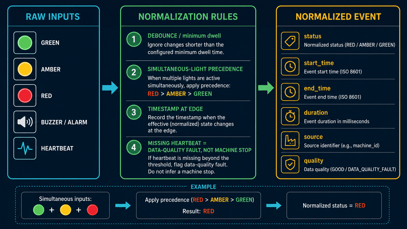
Even when precedence resolves red-plus-green to ALARM, preserve both raw inputs. Give the normalization rule a version and effective time so old results can be reproduced after a rule change.
Distinguish intentional blinking from chatter
Blinking may carry meaning, while contact chatter and communication instability can generate similar short transitions. A single factory-wide debounce value may erase a legitimate fast pattern or preserve noise as an event. During the PoC, retain raw edges and observe actual patterns before setting machine-family rules. Any sample interval used in a workshop must be labeled as a design example, not a general recommendation.
4. Design data quality around time, liveness and missingness
Store more than one relevant time
An event may have a field-change time, transmitter time, gateway-receive time and server-store time. Collapsing them into one timestamp hides network delays and store-and-forward behavior. At minimum, separate event time from receipt time and document time source, time zone and synchronization method. Test clock drift, day and shift boundaries, gateway restart and delayed events.
Use heartbeat to separate “unchanged” from “unseen”
Hours without a transition may mean the machine remained stable—or that the acquisition chain failed. Design liveness at the transmitter, receiver, gateway and upstream-link boundaries as appropriate. Attach quality states such as valid, stale, missing and maintenance.
Do not extend the last observed green state indefinitely through a communication outage. Do not silently replace missing data with zero or stop either. UNKNOWN or MISSING should be legitimate states, with an agreed treatment in KPI denominators and a visible data-quality measure.
Test retries, duplicates and out-of-order events
After a link recovers, buffered events can arrive out of order. Retain enough identity—such as device, input, event identifier, occurrence time and sequence or an equivalent—to prevent double counting. Agree whether and how a late event recalculates an already issued shift report.
Preserve manual corrections as an audit trail
Operators and maintenance staff may need to correct a reason or state. Never overwrite the raw event. Store the automated result, corrected value, user, time, reason and approval separately. A high correction rate is useful evidence that the input or rule may not fit operations.
5. OT cybersecurity and the network boundary
A simple lamp input does not make its connected receiver or gateway risk-free. An unmanaged asset with default settings, unclear update ownership or broad upstream access can expand the attack surface.
NIST IR 8259 Revision 1 was finalized in April 2026 and describes foundational cybersecurity activities for IoT product manufacturers. NIST IR 8259A defines the technical device-capability baseline, while NIST IR 8259B covers non-technical supporting capabilities such as documentation and information support. These are guidance—not a statement that NIST requirements are mandatory for a private Thai factory. Use Revision 1 to review manufacturer lifecycle activities and 8259A/8259B as references when assessing connected devices and suppliers.
The design review should cover:
- asset inventory and ownership for transmitters, receivers, gateways, servers and administration stations;
- authentication, authorization, certificates and storage of secrets;
- only the required direction, destination and service across the OT boundary;
- a controlled update route that does not assume direct Internet access;
- configuration backup, recovery, firmware information and support lifetime;
- synchronized logs and detection of configuration changes or loss of communication;
- approval, time limits and recording for vendor remote support; and
- separation so an acquisition failure cannot propagate into machine control or safety.
Read-only intent is helpful, but safety and security still depend on the actual wiring and network path.
6. From site survey to a comparable PoC and RFP
Plan a legacy machine data collection PoC around differences
The equipment register should record builder, age, tower model, wiring, power, cabinet space, PLC access, radio environment, network zone, shift patterns, operating meanings and maintenance ownership. For wireless, test representative operating conditions rather than replacing the brochure’s reference distance with a site guarantee. For contacts, verify safe branching, downtime and drawing availability.
Make the PoC prove a decision
A 5–10-machine or one-shift PoC can be a scope-design example, never a universal prescription. Select enough variation to cover the machine families, state changes, radio conditions and shifts that will affect a scale decision.
The PoC should demonstrate that:
- representative steady, combined, blinking and buzzer patterns can be observed;
- raw inputs and normalized states are traceable through a reviewable rule;
- power loss, communication loss, restart, retry, duplication and clock issues are distinguishable;
- system events can be reconciled with observations and current production records;
- operator reasons and corrections are auditable;
- account, network, update and backup ownership is defined; and
- the effort to add, replace and support devices can be estimated.
Write an RFP that vendors can answer on the same basis
| RFP section | Required content | Evidence requested |
|---|---|---|
| Scope and assumptions | Asset list, constraints, available drawings | Exclusions and survey dependencies |
| Inputs | Contact, wireless, PLC, IO-Link, blink, buzzer | Compatibility and wiring method |
| State model | Raw, normalized, precedence and versions | Rule table and recalculation method |
| Data quality | Time, debounce, heartbeat, missing, retry | Dictionary, logs and test method |
| Security | Assets, access, boundary, updates, backups | Architecture, roles and recovery |
| Integration | CSV, API, database and dashboard | Schema, error handling and retries |
| Acceptance | FAT, SAT and controlled production | Cases, evidence and correction process |
| Operations | Monitoring, first response, changes, training | RACI and support deliverables |
Our industrial data logger versus factory IoT guide helps distinguish simple capture from a governed operating platform.
Compare cost as a WBS, not an invented market price
Break the commercial response into hardware and adapters; electrical work; radio and network survey; gateway, server and storage; data model and dashboard; security; commissioning and acceptance; training, spares, licenses and lifecycle support. Ask each bidder to mark included, excluded, quantity-dependent and site-confirmation items. Also compare the cost structure for adding machines, changing rules, replacing a gateway and maintaining security—not only the initial purchase.
7. Stage acceptance through FAT, SAT and controlled production
FAT: prove logic and failure behavior
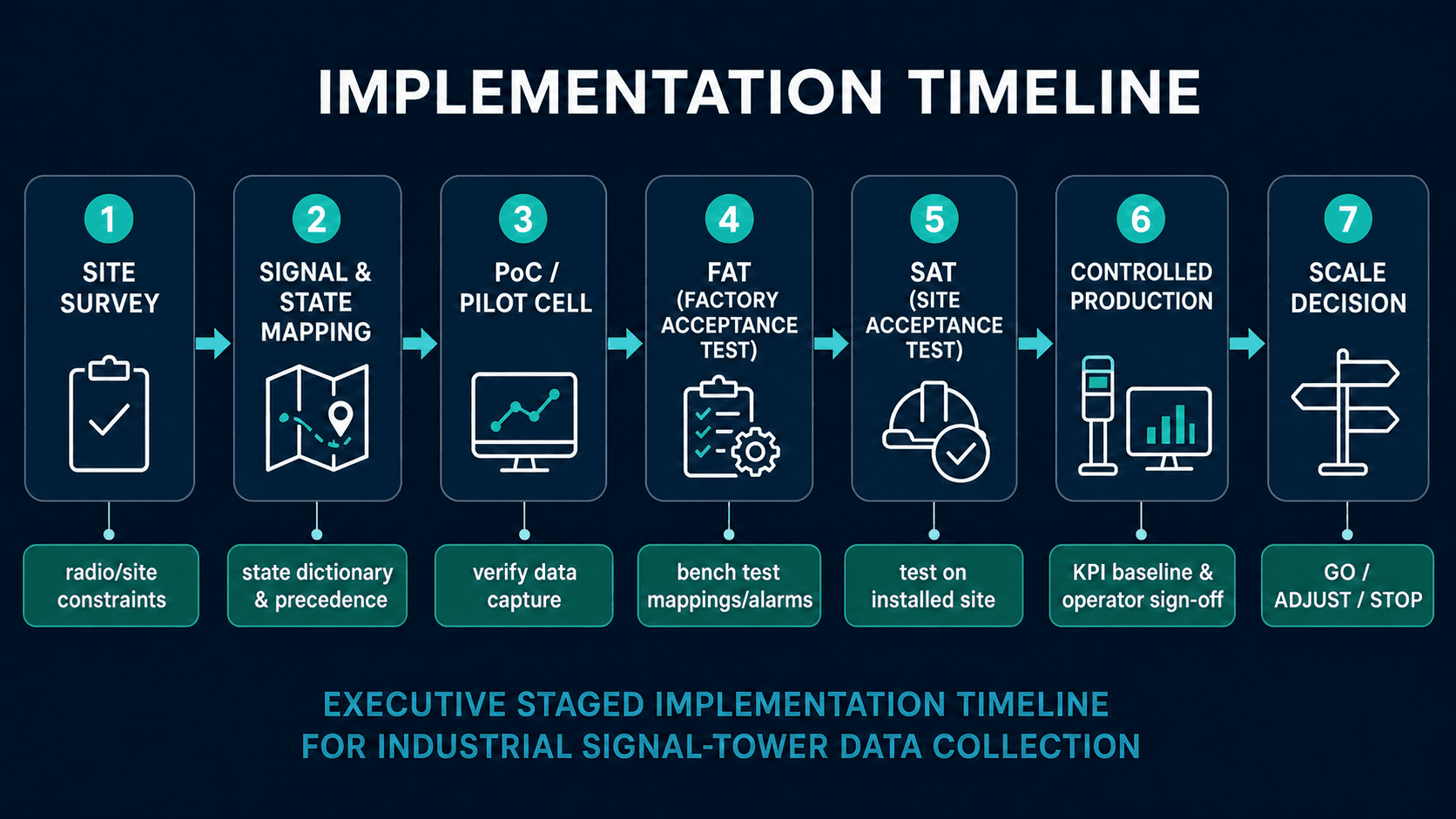
Use simulated or test inputs for individual lamps, combinations, blink and buzzer patterns; short transitions; input or gateway power loss; link outage and recovery; store-and-forward, duplicate and order handling; clock drift and boundary conditions; unknown assets; unauthorized changes; and restoration from backup. Retain expected results, measured logs, deviations and corrections.
SAT: prove the installed result in the Thai factory
SAT includes actual wiring, tower, cabinet, power, radio, network, time source, upstream system and operator workflow. Reconcile observed machine behavior with acquired events. For wireless, acceptance should reflect the agreed on-site method and operating conditions, not a brochure distance. For direct contacts, verify that disconnection or failure of the monitoring circuit has no control or safety impact.
Controlled production: prove that the number supports action
Before scaling, operate a limited production scope and compare the result with reports, work orders, quantities, reason codes and maintenance records. Review UNKNOWN/MISSING time, discrepancies, correction patterns, actionable versus noisy notifications, shift differences and ownership. If criteria are missed, isolate whether the problem is input, rule, operating process or intended use.
8. Derive KPIs without crossing the evidence boundary
Lamp data can support observed input duration, normalized-state duration, transition counts and missing-data duration. Label those measures honestly. “Observed green time” or “normalized ALARM time” is less likely to mislead than unvalidated “actual runtime” or “failure time.”
True cause requires reason or alarm evidence. Cycle time needs a completion event or count. OEE requires planned time, quantities, quality and an agreed speed basis. Write a definition sheet for every KPI: purpose, formula, numerator, denominator, source, exclusions, missing-data treatment, update frequency, owner and meeting where it is used.
A dashboard should expose data freshness, missingness, rule version, machine scope and time period, and allow a user to trace a number back to events. Its job is not to assign blame; it should help an owner decide the next check and due date.
9. Assign operating ownership
| Operating task | Likely owner | Controlled record |
|---|---|---|
| Register assets, transmitters and inputs | OT / maintenance | Asset map and drawings |
| Approve state meanings | Operations + maintenance | Versioned state table |
| Manage gateway and network | IT / OT | Configuration, access and backups |
| Respond to missing data | Monitoring owner | Alert, diagnosis and restoration |
| Maintain reason-code quality | Operations | Reasons and correction trail |
| Govern KPI definitions | Business owner | Definition and approval history |
| Manage updates and product support | Asset owner + supplier | Version, test and rollback |
The exact RACI varies, but machine failure, semantic error, network failure and operating-process failure should not disappear into one ambiguous help desk queue.
10. Implementation checklist
Concept and survey
- [ ] Define the business decision to improve.
- [ ] Verify tower model, wiring, drawing and operating standard.
- [ ] Map colors per machine; do not assume universal meanings.
- [ ] Include combinations, blinking, buzzer, all-off and manual modes.
- [ ] Compare contact, wireless, PLC/IO-Link and mixed designs.
- [ ] Plan an on-site radio survey where wireless is used.
Data and cybersecurity
- [ ] Separate raw, normalized, event and KPI layers.
- [ ] Define timestamps, time source, time zone and clock checks.
- [ ] Define debounce, heartbeat, missing, retries and duplicates.
- [ ] Preserve manual correction history.
- [ ] Inventory devices, owners, access and support status.
- [ ] Constrain the OT boundary and prove control/safety separation.
PoC and acceptance
- [ ] Select variation, not a convenient machine count alone.
- [ ] Test combinations and failure paths in FAT.
- [ ] Verify the installed environment and operators in SAT.
- [ ] Reconcile against production evidence in controlled operation.
- [ ] Record criteria, evidence, correction and the scale decision.
- [ ] Compare the complete WBS and lifecycle responsibilities.
Frequently asked questions
Can signal tower data collection calculate OEE by itself?
No. Tower duration is observation data. OEE needs planned time, count, quality and an agreed speed basis, together with defined handling of missing and unknown periods. Validate each component before presenting the result as OEE.
Can stack-light monitoring be retrofitted to an old machine?
Often, if a compatible tower or safely accessible contact exists. PATLITE describes WD use for compatible towers irrespective of machine age or model, but exact model compatibility, wiring, power and receiver configuration must be verified.
Is wireless better than wired capture?
Neither is universally better. Wired capture brings electrical work and routing questions; wireless brings compatibility, power, radio and receiver-failure questions. PLC access may be richer where it is authorized. Compare all relevant failure and maintenance paths in the survey and PoC.
Can a catalogue radio distance be used as the acceptance criterion?
No. It is a reference under specified conditions. Define and test an on-site criterion under representative Thai factory conditions.
How many legacy machines should a PoC include?
There is no universal count. A range such as 5–10 machines is only a design example. Choose a scope that represents the differences that could change the architecture or scale decision.
How should a buyer compare signal tower data collection cost?
Use a WBS covering field hardware, electrical work, surveys, gateway/server, data model, cybersecurity, commissioning, training and lifecycle support. Require assumptions and exclusions instead of relying on an unsupported market-average price.
Is a CSV export enough for a factory dashboard?
It can be a transport format, but it does not create trustworthy semantics. Add governed identities, timestamps, quality flags, deduplication, state-rule versions and reconciliation with business data.
Conclusion: turn a low-intrusion observation into an explainable operation
Signal tower capture is valuable because it can open a path into legacy equipment with limited control changes. Its limitation is equally important: a lamp is an observation point, not a universal source of truth for cause, cycle time or OEE. Separate raw inputs, normalized states, business events and KPIs; map each machine; and design timestamps, heartbeat, missing data and corrections as first-class requirements.
Choose direct contacts, a wireless add-on, PLC/IO-Link or an edge combination according to the installed estate and operating owner. Use a site survey, comparable RFP, failure-oriented FAT, on-site SAT and controlled production to accept an actionable, explainable result—not merely a moving dashboard.
TOMAS TECH can support concept design, a Thailand site survey, PoC scope, state mapping, RFP preparation and FAT/SAT acceptance definition. If you are still deciding where to start across mixed-age machines, you can contact us while the architecture and acceptance criteria are still open.
References
- PATLITE WD System Instruction Manual: https://shop.patlite.com/v/vspfiles/downloadables/WDSystem_InstructionManual.pdf
- PATLITE WD product description: https://shop.patlite.com/article-a/287.htm
- PATLITE WD-Z2 / WD PRO brochure: https://pd.patlite.com/portal/documents/WD-PRO_Enhanced_Wireless_Data_Acquisition_System.pdf
- IO-Link Community: https://io-link.com/
- IO-Link downloads: https://io-link.com/downloads
- NIST IR 8259 Revision 1: https://csrc.nist.gov/pubs/ir/8259/r1/final
- NIST IR 8259A: https://csrc.nist.gov/pubs/ir/8259/a/final
- NIST IR 8259B: https://csrc.nist.gov/pubs/ir/8259/b/final


