


Selecting a servo drive regenerative resistor by matching a wattage to the motor rating can leave a production machine with regenerative alarms during repeated short cycles or unexpected cabinet heat. This guide helps engineering teams in Thailand specify the exact drive and resistor combination, estimate returned energy, compare peak and average thermal loads, wire protection, and define factory and site acceptance tests.
The servo motor and drive are assumed to be provisionally selected. For motor torque, inertia and speed sizing, see our servo motor selection guide. This article addresses whether the drive’s built-in regeneration capability is enough and, if not, which approved external option and installation conditions should be ordered.
The decision: order the drive, duty cycle, heat path and protection as one system
A regenerative resistor is not interchangeable merely because its ohmic value or wattage appears similar. The drive determines the permitted external resistor, minimum resistance, terminals, internal-to-external changeover, parameters and energy limits. Mitsubishi Electric’s MR-J5 documentation calls for a specified regenerative option and matching parameter when built-in capacity is insufficient. Omron’s 1S compatibility table assigns different ohmic values and processing capacities to different drive models. A wattage comparison across brands is therefore not evidence of compatibility.
Put six items into the procurement specification: the full servo drive model and input voltage class; actual speed, load and stopping profile; the manufacturer-approved resistor model and settings; heat rejection inside or outside the cabinet; the path from the resistor’s temperature contact to a controlled stop; and records from production-condition tests. When the drive is not yet fixed, require the supplier to present a documented drive–resistor pairing instead of ordering a resistor alone.
A vertical electric cylinder, a heavy indexing table, and a winding axis are examples of loads that may regenerate. Their machine names do not prove that an external resistor is required. Mass, speed, deceleration, holding method and energy exchange with other axes change the result. Define thrust and speed using our electric cylinder selection guide, then complete the electrical regeneration assessment here.
What regeneration does, and why it is not a holding brake
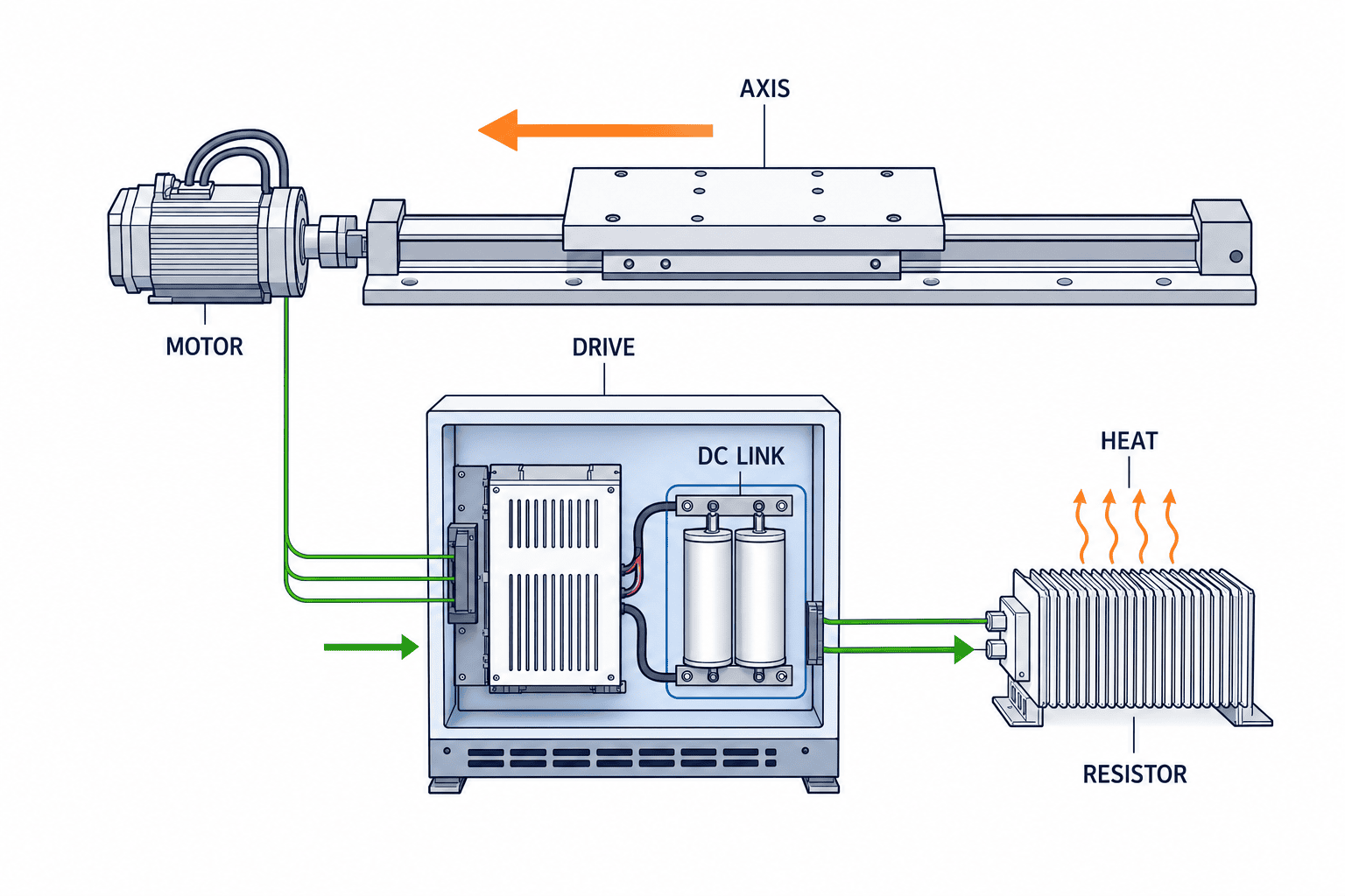
During acceleration, electrical energy passes through the drive to the motor. During deceleration, inertia may keep turning the motor; on a descending vertical axis, gravity can do the same. The motor then returns energy to the drive’s DC link. After the DC-link capacitors can no longer absorb the return, a suitable drive uses its regeneration circuit and resistor to turn electrical energy into heat. Exceeding the system’s ability to absorb it can cause DC-link overvoltage or regenerative alarms.
A motor’s electromagnetic holding brake has a different purpose. It holds a stopped load; the regenerative resistor processes returned energy while the axis moves or decelerates. More resistor capacity is not fall protection. The behavior during an emergency stop, power loss, drive fault and restart belongs in the machine safety design. On a descending axis, evaluate what holds the load after a regenerative fault trips the drive.
The energy path also depends on architecture. A single-axis drive may use an internal or external resistor. In an approved common DC-link system, an accelerating axis may consume energy from a decelerating axis. Beckhoff’s AX5000 documentation sizes such a group for both continuous and short-duration braking power and checks the minimum permitted resistance. The manufacturer’s compatibility rules determine whether a common bus is allowed. Do not copy a single-axis wiring diagram into a multi-axis machine.
Gather operating data before choosing a component
The starting point is the most demanding operating cycle, not the motor’s catalogue kW. A slowly stopped axis and a heavy axis repeatedly stopped within a short takt impose different heating even with the same motor. For each production recipe, record travel, top speed, acceleration, deceleration, maximum product mass, cycle time, dwell before restart and continuous running duration. Separate upward and downward conditions if their loads differ.
Distinguish design assumptions from measured values. Equivalent inertia, gearbox ratio and screw lead can support a first energy estimate, but a PLC recipe change or a mixed product run changes the actual profile. Identify which drive signals can be logged: axis velocity, torque or current, DC-link voltage, regenerative load factor and alarm history. Mark unavailable measurements as such and plan how they will be checked at FAT.
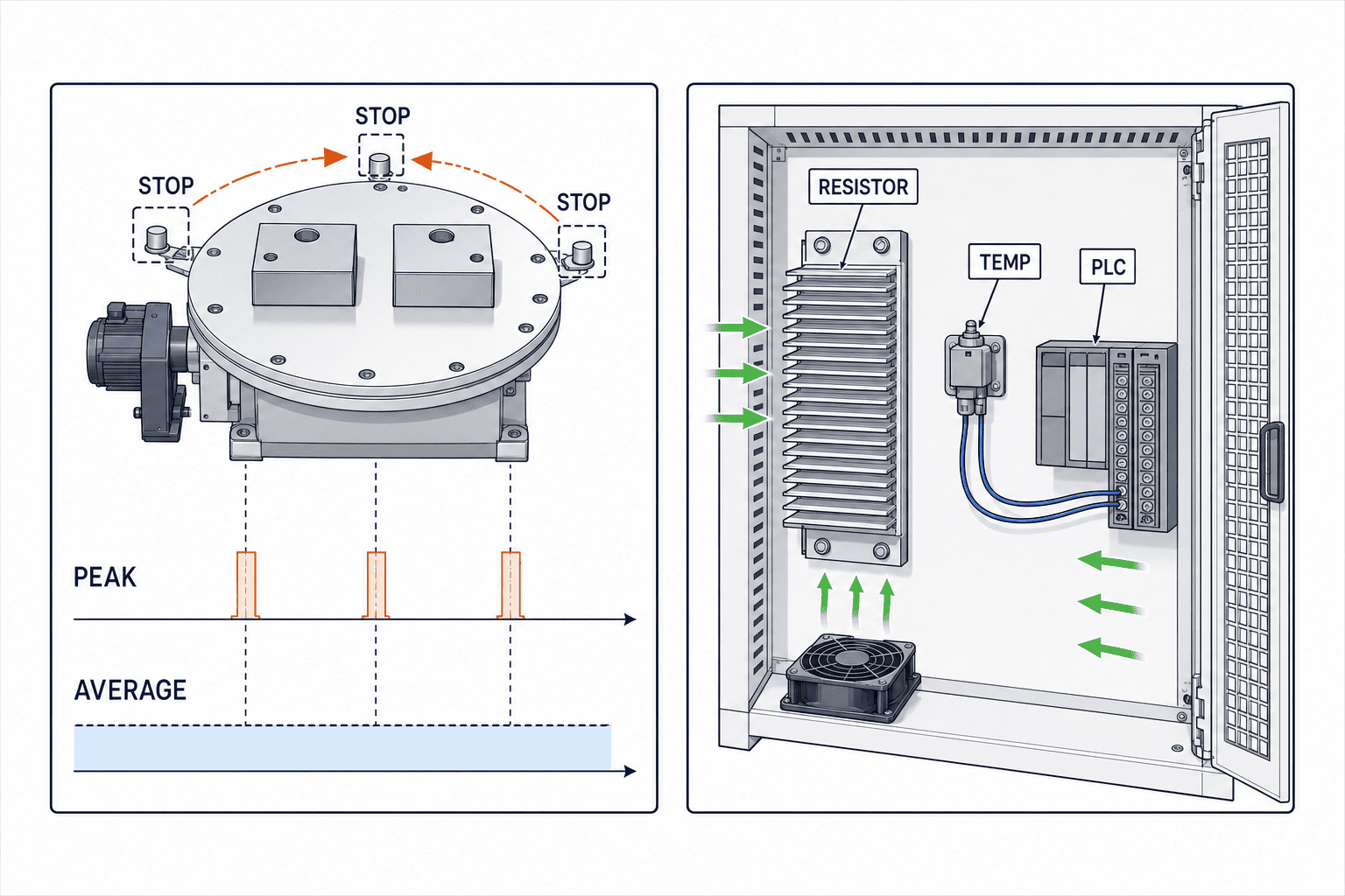
The heaviest product is not always the worst case. A lighter product may run faster; operators may shorten takt; several axes may decelerate together. Compare normal production, fastest continuous production, maximum mass, shortest stop, changeover and a controlled abnormal stop. State which condition drives peak energy and which drives average heating. Any safety-related stop test must follow the equipment maker’s approved procedure; protection must not be disabled to obtain a number.
For a Thailand plant, compare the Japanese design recipe with the actual local operating recipe. Specify which is guaranteed. Record cabinet temperature, ventilation, dust and nearby hot equipment at the same time. A precise regeneration calculation does not complete the design until the heat has a safe destination.
Estimate energy per stop and energy over repeated stops separately
For a simplified rotating system with equivalent inertia J and angular velocities ω1 and ω2, the kinetic-energy difference during deceleration is 0.5 × J × (ω1² − ω2²). A descending vertical axis also changes potential energy. This is a mechanical starting point, not a claim that the entire amount enters the resistor. Friction, gearing, motor and drive losses, DC-link storage and simultaneous consumption by other axes all matter.
Suppose, solely to illustrate the arithmetic, that 100 J reaches the resistor in one stop and the shortest cycle repeats every five seconds. The simple cycle average is 20 W. That figure alone cannot size the part. Verify short-duration energy and peak power, allowable duty, ambient temperature and drive chopper limits. The example numbers are not product ratings. Use the selected manufacturer’s sizing tool or manual and compare the calculation with measured regenerative diagnostics during commissioning.
Continuous use requires more than energy per stop multiplied by stops per minute. Ask how many demanding cycles occur consecutively and whether the machine rests long enough to cool. Thirty minutes of operation followed by a long pause differs from the same cycle repeated across shifts. Manufacturers express limits as continuous watts, short-duration joules, duty ratio or monitored regenerative load; match the time window in the source manual to the actual cycle.
When a quotation lists only “required W,” ask for energy per stop, peak watts, repeat period, continuous operating time and assumed ambient temperature. One supplier may quote a continuous value and another a momentary peak. Keep formulas, inputs, sources and the reason for any margin in the calculation sheet. The margin should reflect measured uncertainty and manufacturer limits, not an arbitrary universal multiplier.
Decide whether the built-in capability is enough
Look up the built-in regenerative capacity using the drive’s complete model designation and the manufacturer selection method. If it covers all approved recipes and the cabinet remains within its temperature limits, an external resistor adds components, wiring, heat protection and spare parts without clear benefit. If it is insufficient, compare the approved external resistor, brake unit or regeneration unit architectures offered for that exact drive.
Read the compatibility conditions literally. Mitsubishi’s MR-J5 has specified regeneration options and settings, and some variants cannot use them. Its hardware documentation also identifies configurations where a brake unit and regenerative option cannot be combined. Omron’s 1S table varies resistance and capacity by drive model. Yaskawa’s Sigma-7 manual changes terminals, jumper treatment and parameter settings by SERVOPACK model. Include the relevant manufacturer table in the purchase package.
Substituting a generic resistor with the same nominal ohms requires approval for pulse-energy capability, insulation, temperature contact, mounting, certification and warranty as well as resistance. Too low a resistance can overload a chopper; too high a resistance can reduce effective peak braking. Schneider Electric’s Lexium 32M manual, for example, lists model-specific minimum and stated maximum external resistance, with a note that higher resistance may be possible at reduced peak power in some conditions. Check the exact model’s approved range and performance; do not transfer its values to another drive.
If an external resistor has been fitted but alarms remain, do not assume it is undersized. Mitsubishi’s troubleshooting documentation also lists wrong parameters, terminal or jumper wiring, incompatible combinations, excessive supply voltage and frequent positioning as causes. Correlate the alarm time with the recipe, wiring, settings and supply before changing the motion profile or hardware.
Thermal design includes the destination of the heat
Energy handled by a resistor becomes heat. Inside a cabinet it adds to cooling load; outside it needs protection from personnel contact, cables, plastic parts, dust and oil. Manufacturer instructions for spacing, mounting orientation and combustible materials matter. Mitsubishi’s MR-J5 hardware manual notes that certain resistor-unit surfaces can become much hotter than ambient and requires the relevant error outputs to be connected to a power shutoff circuit. Treat its figures as specific to the listed products.
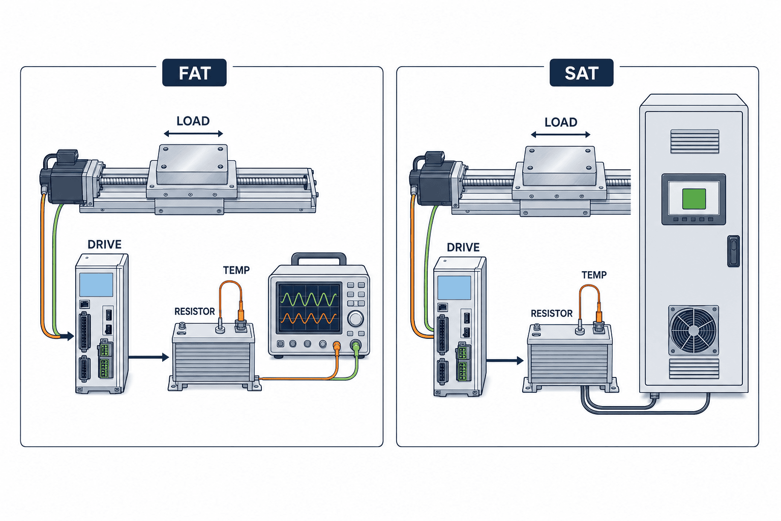
Draw the selected location, orientation, clearance, airflow, nearby cable route, guard, maintenance access and temperature-contact wiring on one installation drawing. Outside the cabinet, also check the applicable ingress protection and exposure to washdown, water, dust, salt and impact. An air-conditioned FAT room can mask the heat load that appears in an installed Thailand cabinet; SAT should measure the actual location under normal ventilation.
The mere presence of a temperature switch does not make a protective system. Beckhoff describes evaluating the switch in the drive or PLC. Document which input changes when the contact opens, which alarm is logged, how the axis stops, who authorizes a reset and how maintenance staff wait for the resistor to cool. Where safety-rated functions are required, conduct a separate safety assessment rather than assuming one ordinary PLC input is sufficient.
What to request in the RFP and compare in the quotation
Ask for five evidence packages. First, the drive, motor, resistor and any brake-unit model numbers with the manufacturer compatibility document. Second, a calculation for regenerative energy plus peak and mean power for every demanding recipe. Third, resistance, continuous and short-term capacity, duty limits and temperature derating. Fourth, the circuit, jumper changes, parameters, temperature contact and stop sequence. Fifth, dimensions, spacing, cabinet heat, spares and local lead time.
Compare candidates on model compatibility, proof at minimum takt, high-temperature margin, heat location, fault response and Thailand replacement support. Compare total installed cost: resistor, cabinet modification, ventilation, wiring, guards, software settings, FAT, SAT and spare parts. A generic published price cannot account for a particular existing cabinet.
An RFP clause can say: “For the specified servo drive, calculate the suitability of built-in regeneration and need for an external option under maximum load, minimum takt and repeated descent, following the manufacturer’s procedure. Submit compatibility evidence, wiring and settings, installation and thermal plan, temperature protection, and FAT/SAT measurement methods and acceptance criteria.” List data that remain unmeasured and decide whether site measurement or FAT will close each gap.
Give competing suppliers the same duty profiles and response template. If one assumes a slower stop and another a lighter product, their prices cannot be compared. Alternative architectures should disclose differences in construction and fault behavior as well as claimed capacity.
FAT checks the waveform and sustained operation
Before energizing at FAT, verify nameplates, resistance, terminals, jumpers, cable specification, grounding, temperature contact, protective input and parameter backup against the approved drawing. Then run representative maximum-load, shortest-takt and continuous conditions. Record regenerative load or DC-link voltage where the selected drive exposes them, alarm history, resistor-area temperature and cabinet temperature on the same timeline. Agree on a manufacturer-approved measurement method if the drive has no built-in diagnostic.
Define the guaranteed operating envelope before the test. A pass with product A at a comfortable takt does not prove performance for heavier product B at the shortest takt. Record product mass, travel, acceleration and stop settings and cycles per hour for every test. If actual workpieces are unavailable at FAT, have the machine designer justify an equivalent load and reserve unrepresented conditions for SAT.
Keep the measurement method with the result: instrument, sampling interval, temperature-sensor location, cabinet door and ventilation state. Check whether a drive display means an instantaneous, averaged or accumulated value. Beckhoff’s AX5000 documentation provides an example of diagnostics for average resistor power and peak energy. It is an example of what to seek on the selected drive, not a universal standard. A single stop can pass while repeated stops overheat; a low long-term mean can also hide a damaging single peak.
Measure during startup and after temperature stabilizes. Check heat reaching nearby cable insulation or controls, not just the average cabinet air. If FAT requires a motion or resistor change, update the sizing calculation, parameter backup, drawings and spare-part list together. A longer deceleration can reduce one load while damaging takt or accuracy; keep its rationale and test record under the equipment revision.
Test protective behavior with an approved procedure. If the design supports simulating an opened temperature contact, obtain machine maker and safety-team approval, then verify alarm, controlled stop, restart interlock and recovery. Do not overheat the resistor deliberately or bypass protection. Attach recipe, product, ambient condition, software revision, measurement points and witnesses to the result.
SAT repeats the test in the real Thailand installation
First compare the installed configuration with the FAT-approved bill of materials. A locally substituted resistor, bracket, cable or fan is not “equivalent” until compatibility and installation are approved again. Confirm voltage, grounding, cabinet placement, nearby heat sources and actual product mass. If the resistor moved outside the cabinet, verify cable type, length, fixing and guarding against the product manual.
Run the production recipe with normal cabinet covers closed and normal ventilation enabled. Real operations reveal recipe switching, product feed variation and shortened waits that manual jogging misses. Time-align the production log and regeneration diagnostics. If workpiece supply stops during a planned endurance test, record the interruption rather than reporting a full continuous-load pass.
SAT acceptance should include the agreed maximum load, shortest takt, worst descent and representative sustained operation, with diagnostic and temperature values inside the selected manufacturer’s limits. Check that settings survive a stop and restart, local maintenance staff can interpret alarms and replacement can be verified. A later takt reduction is a change to the approved operating envelope and should trigger another assessment.
Provide Thai or English alarm names, model identifiers, terminal drawings, backups, spare location, cooling wait and post-replacement test recipe to local maintenance. Monitor regenerative load, cabinet temperature, alarm frequency and recipe revisions by machine ID. Establish alert levels from FAT/SAT normal ranges and the exact manufacturer’s limit rather than applying one threshold to all drives.
Three operating cases require different checks
For a horizontal indexing axis, every stop returns kinetic energy. Equivalent inertia, deceleration time and stops per hour matter more than motor nameplate power alone. Test the fastest and heaviest recipes separately; one may maximize peak load and the other average heat.
For a descending vertical axis, gravity can drive regeneration throughout travel, not only at the final stop. Evaluate the complete descent and separately design the holding brake, fall prevention and behavior after a drive fault. Those safety functions are not supplied by the resistor.
For a multi-axis system, one accelerating axis may consume another’s returned energy, while simultaneous stopping may concentrate it. Verify common DC-link eligibility, connection point, protection and worst-case group calculation in the specific drive documentation. An old resistor on a retrofit also needs new-drive approval and inspection; visual similarity is not enough. If future production takt is planned, state future load, speed and repeats separately from the present guarantee and ask when the architecture must change.
Troubleshoot in a fixed order
When a regenerative alarm occurs, first capture code, time, recipe, motion phase and supply voltage. Then check complete drive and option models, terminal/jumper wiring and parameters against the manual. Only then compare peak and mean regenerative load, temperature, recent cycle changes and simultaneous axes. Mitsubishi’s MR-J5 troubleshooting guide lists several of these alternative causes in addition to exceeded capacity.
A warm resistor is not automatically out of specification, but heat must not be dismissed. Measure at the prescribed location and operating condition. Odor, discoloration, cable damage or a tripped temperature contact warrants stopping and investigation. Follow electrical isolation and cooling procedures before inspection. If a larger resistor appears to cure a fault, still verify that the production recipe has not changed the original duty assumption.
FAQ: servo drive regenerative resistor selection
Is a resistor with the same wattage as the motor sufficient?
No conclusion follows from the motor rating. A motor’s continuous output is different from returned joules per stop, peak watts and repetition duty. Use the complete drive compatibility data and its manufacturer’s sizing procedure.
Can an external resistor simply be added in parallel with the built-in one?
There is no general permission to do so. Some drives disable the internal resistor when an external option is enabled; others require jumper or terminal changes. Follow the manual for the exact model. Never infer compatibility from matching resistance alone.
Should I extend deceleration whenever a regenerative alarm appears?
Changing deceleration may change peak loading, but it cannot correct wrong wiring, settings or high supply voltage and may alter takt or stopping distance. Diagnose the recorded alarm and duty profile before changing motion.
How should prices be compared?
Compare the complete approved system, including any brake unit, cabinet work, cooling, protective wiring, startup, spares and FAT/SAT. Ensure all quotations use the same recipe and distinguish continuous from short-duration ratings.
Summary
Select the resistor from the real motion profile, then validate the chosen drive’s internal capability and approved external options. Check peak and repeated energy, thermal installation and protective behavior under the same conditions that production will use. Keep compatibility evidence, calculations, drawings, backups and acceptance records together so a later recipe change can be assessed reliably.
If your load profile or cabinet layout is still being defined, the measurements and RFP scope can be agreed before purchase. For a Thailand servo-axis regeneration assessment and acceptance plan, contact TOMAS TECH.
Manufacturer references
- Mitsubishi Electric MR-J5 Function Manual
- Mitsubishi Electric MR-J5 Hardware Manual
- Mitsubishi Electric MR-J5 Troubleshooting
- OMRON 1S external regeneration resistor compatibility
- Yaskawa Sigma-7S Product Manual
- Beckhoff AX5000 System Manual
- Beckhoff braking resistor diagnostics
- Schneider Electric Lexium 32M User Guide


