


Selecting a solenoid valve manifold by the number of available stations alone can leave a machine with slow cylinders, interacting exhaust flows, insufficient PLC outputs, or lengthy valve replacement. For a Thailand factory, selection must cover the complete valve bank: individual valve functions, common air supply and exhaust, electrical interfaces, installation and maintenance. This guide helps machine engineering, controls, procurement and maintenance teams write one comparable RFP and one set of acceptance tests. It does not recommend a particular manufacturer or treat a catalogue rating as a guaranteed machine result.
Define the scope of solenoid valve manifold selection
A manifold mounts multiple directional valves on a common base and consolidates supply, exhaust and electrical connections. For the fundamentals of a single 3/2, 5/2 or 5/3 valve, pilot pressure and manual override, see our single solenoid valve selection guide. This article addresses the next decision: which valves should share a bank, how many banks are needed, and how the common flow paths and PLC interface are designed. An individual valve can have adequate flow while a narrow supply header, simultaneous exhaust or long tubing prevents the installed cylinder from meeting its cycle time.
Inventory more than the number of valves
Build a row for every actuator: equipment tag and location, motion, cylinder bore and stroke, required cycle, working pressure, holding requirement, safe state on stop, sensor and PLC I/O. A single-acting cylinder, double-acting cylinder, vacuum device, air blow and gripper cannot all be counted as one identical “valve.” They can need different ports, outlet tubing, exhaust handling and output counts. Specify whether future spare stations are empty bases only or include fitted valves and reserved control outputs.
Record the maximum group of valves that changes state at once. Eight valves operating sequentially impose a different peak load on shared supply and exhaust from eight valves switching together. Read the machine sequence, including start-up, homing and recovery after an emergency stop. Assign mechanical engineering the load and motion requirements, pneumatics the air paths and pressure, controls the signals and diagnostics, and maintenance the replacement procedure. Each discipline must approve the same schedule.
Fix interfaces before comparing quotations
Give bidders the supply voltage, PLC model, existing network, pipe and fitting standards, tube outside diameters, installation envelope, ambient temperature, and exposure to water, dust, oil mist or washdown. A small suffix difference in a catalogue number may change connector, port orientation, ingress protection or output polarity. Require the complete assembled part number, assembly drawing, each valve part number and communication module part number. SMC’s SY manifold specification list, for example, includes individual wiring, D-sub, ribbon-cable and gateway configurations within the same family. A family name is not a purchasable specification.
Calculate stations, outputs and spare capacity separately
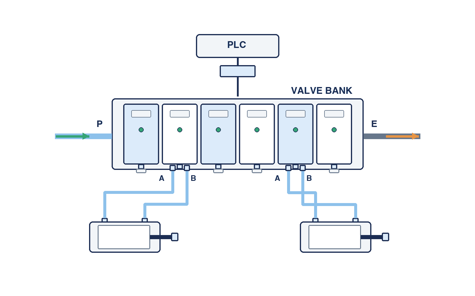
A “12-station manifold” does not necessarily control 12 actuators. One station’s valve function, single or double solenoid, compatibility with mixed 3-port valves and the communication unit’s output capacity all matter. Keep station count and PLC output count in separate columns. A single-solenoid valve generally requires one drive output and a double-solenoid valve two, but check the mapping for the selected unit. SMC’s EX260 documentation includes 16-output and 32-output variants and describes assignment of output numbers to solenoid positions.
Work from a tag schedule, not an assumed percentage
Suppose a design needs six single-solenoid valves for double-acting cylinders, two double-solenoid valves and two empty future stations. This illustrative design, not a product rating, needs ten physical stations, eight installed valves and ten current drive outputs. Confirm whether the candidate requires blanking plates, its maximum expandable station count, and whether the communication unit still has outputs after expansion. An empty station without spare outputs can force a later SI-unit replacement.
Copy the station-to-output mapping into both electrical drawings and PLC tags. A later change from single to double solenoid may fit the same physical station while consuming one more output. Recheck the communication limit, occupied PLC area and actual wiring. If a temporary manual valve is fitted during commissioning, mark it as temporary and reconcile the as-built production configuration. A universal “20% spare” rule has no technical basis. Size reserve for a known future function and date; for uncertain expansion, weigh the value of reserve against length, space, cost and additional spare-part variants.
Describe future expansion by the motion to be added and when it will switch, not only by a process name. An air blow added to a new inspection process may overlap an existing clamp, requiring a fresh calculation of peak supply and exhaust backpressure as well as a spare station and output. Revisit reserve when the expansion plan changes; document what can be added without replacing the base or communication module.
Determine ports from actuator behaviour on failure
The choice of 5/2 or 5/3 and its centre condition affects workpiece drop, clamp release, trapped air and unintended movement on restart. Do not fit every axis with the same valve solely for a neat common bank. Derive the stop condition from machine risk assessment; where needed, add a separate holding device, mechanical stop or safe exhaust arrangement. A valve’s de-energised position alone is not a machine safety function. State the expected condition for loss of electricity, air and communication for each output so FAT can reproduce it.
Translate valve flow ratings into an installed-system calculation
Required flow depends on bore, stroke, target time, supply pressure, tube length, fittings, speed controller, silencer and simultaneous motion. SMC’s plug-in SY catalogue lists different flow-characteristic C values for SY3000, SY5000 and SY7000; these are model-specific examples, not guaranteed cylinder speeds. Ask the supplier to calculate the candidate valve under relevant upstream and downstream pressure conditions, including supply and exhaust pressure losses, then measure the installed circuit.
Check each valve and the common headers
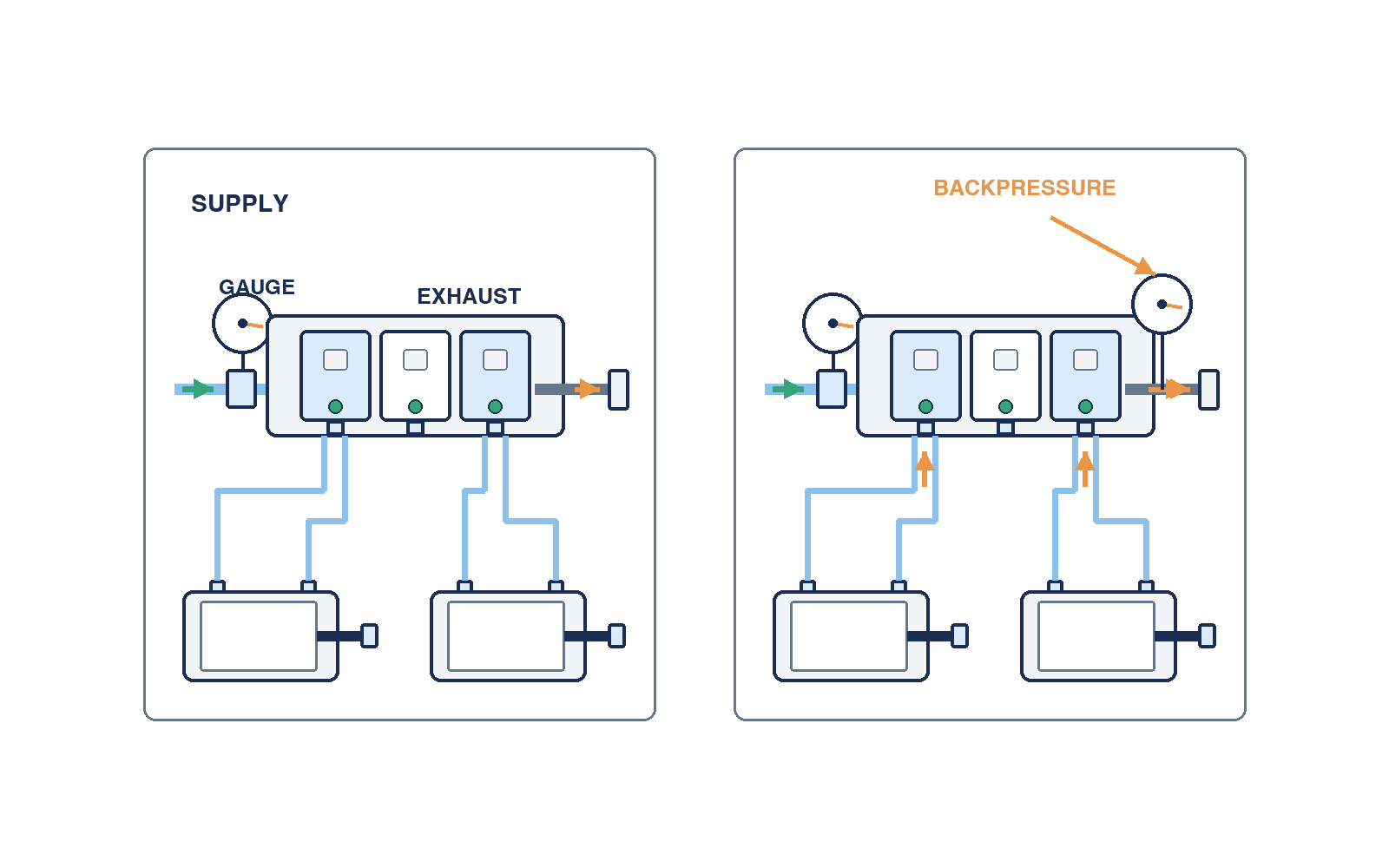
For the most demanding actuator, give the bidder required motion time or effective flow, operating pressure, tube internal diameter and length, fitting count and the speed-controller adjustment range. Provide the simultaneous switching sequence. Ask whether the common P supply can support it and whether backpressure at the E exhaust affects other valves. Air blow and precise cylinder control on the same supply zone may cause a transient pressure disturbance. The answer may be larger feed connections, separate zones or separate exhausts; it depends on the actual circuit and cannot be prescribed for every machine.
Buying a smaller valve and compensating later by raising supply pressure can increase leakage, consumption and component stress. Select the valve, tubing and speed controller for the real load first. The manifold must deliver and exhaust enough air for that adjustment to work. A speed-controller setting cannot overcome an undersized common header.
Do not leave exhaust until commissioning
Common exhaust simplifies installation, but peak simultaneous exhaust, silencer fouling, backpressure, noise and the outlet environment need review. One cylinder exhausting while another positions can create variability if a shared exhaust header sees a pressure rise. Include normal and worst-case concurrent sequences in the RFP. Price separated exhaust or additional zones where justified. FAT must run the overlapping machine sequence, not only one valve at a time.
Draw supply zones, regulation and residual-air handling
If functions need different pressures, compare one common supply with downstream regulation against pressure zoning inside the bank. Product compatibility, feed ports, separation plates, spacers and regulator positions affect the exact assembly number. SMC describes manifold-compatible individual pressure-regulation options; Festo’s VTUG documentation gives a concrete example of pressure zones and separated exhaust. These are product-specific examples. Require each bidder to mark zone boundaries, supply entries and whether exhaust remains shared on the proposed assembly drawing.
Validate pressure under motion, not just at rest
For a high-pressure clamp and low-pressure transfer on one base, draw upstream pressure, zone settings, fault isolation, gauges and sensor locations on one pneumatic diagram. A regulator does not remove upstream fluctuation or downstream consumption. Measure dynamic pressure and motion during simultaneous operation. Document the reasons for settings and who may change them. Our pneumatic pressure regulator guide covers regulation in more detail; for a manifold, the key is how the zones interact.
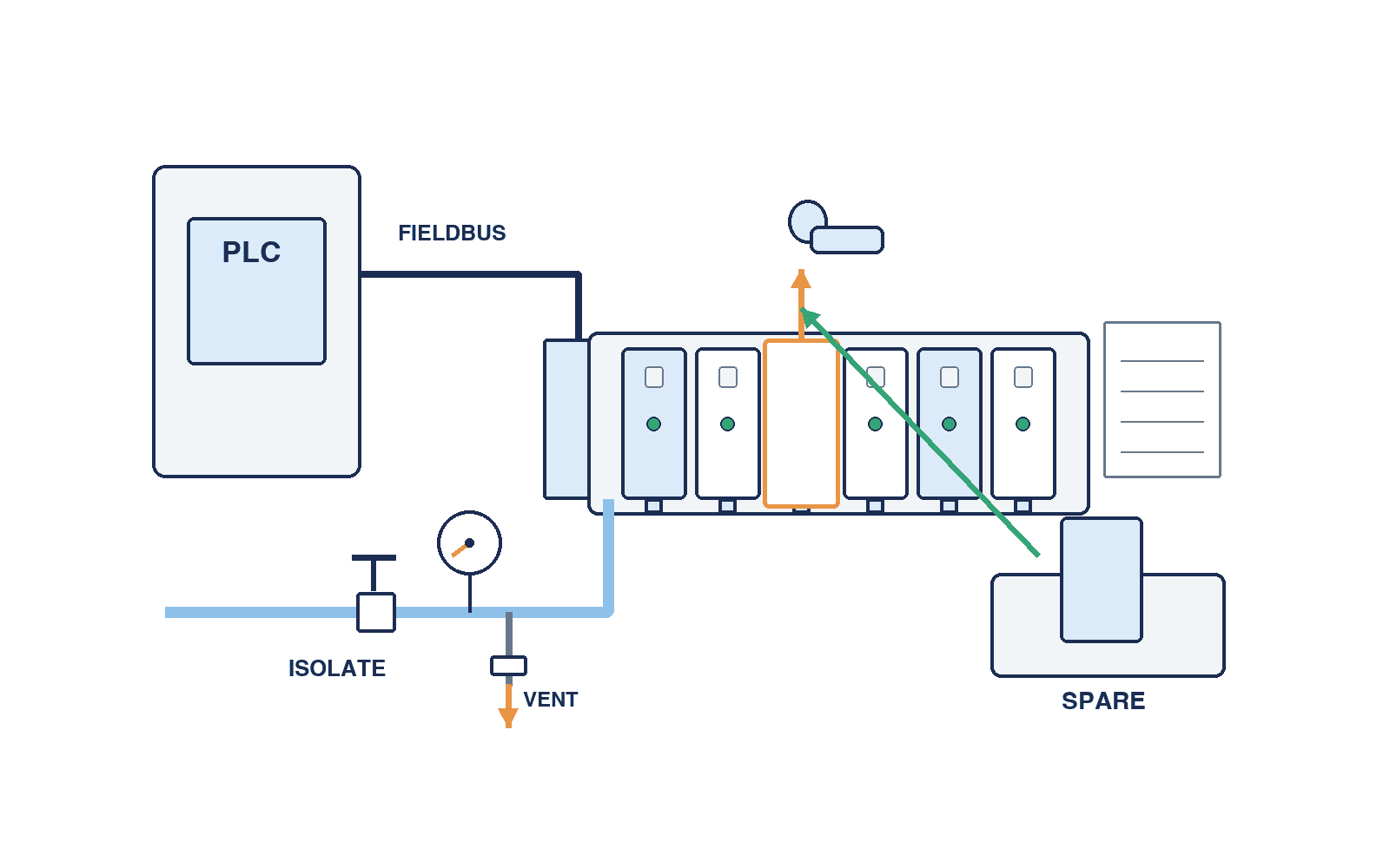
Switching off electrical power does not necessarily release stored compressed air. The machine’s risk assessment and maintenance procedure must define the shutoff and vent valves, the gauge used to confirm zero pressure and mechanical support for moving axes. Where different pressure zones share exhaust, verify that the exhaust path cannot unintentionally feed another zone.
Choose individual wiring or fieldbus from signals and diagnostics
Individual wiring can be straightforward to trace when there are few valves close to a control cabinet. As valve count and distance grow, terminals, cable routes, installation and miswiring checks become significant. Fieldbus can consolidate cabling, provide diagnostics and integrate I/O, but adds a communication module, network configuration and recovery procedure. Emerson describes its G3 as a platform integrating pneumatic valves and I/O with configuration and diagnostics. A protocol name alone does not establish PLC compatibility.
Reconcile the PLC signal schedule
For each proposal, request protocol/version, configuration file, input and output counts, PNP/NPN output polarity, separated power supplies, connector, protection rating, behaviour on network loss, restart procedure and diagnostic-bit meanings. SMC EX260 material shows 16/32-output, polarity and protocol variations. “EtherNet/IP compatible” alone does not confirm the EDS, PLC input/output area and actual solenoid mapping. A manifold with many double-solenoid valves consumes more outputs than one with the same number of single-solenoid valves. Reserve outputs explicitly for future stations.
Test network loss and reconnection on the real PLC program. Do not infer a safe state from a communication unit’s default. Record IP address or device name, firmware, configuration file and backup so a replacement unit can be commissioned without guesswork. Decide which failure information operators see at the HMI and what a technician needs to identify a failed station.
Specify the diagnostic boundary
Fieldbus does not diagnose every pneumatic fault. Electronic communication or output faults are different from air leaks, blocked silencers and seized cylinders. Integrating nearby sensor inputs expands the available evidence, but also changes the scope of configuration and maintenance. Start with real failure history, choose the useful signals, and state who acts on each alarm. Do not purchase a diagnostic feature merely because it appears on a product sheet.
Place the bank for air performance and service access
Mounting a bank inside the electrical cabinet may protect electronics but lengthen actuator tubing. Mounting near actuators may shorten tubes but exposes equipment to heat, vibration, water, oil and dust and needs cable protection. Verify ingress ratings for the assembled unit with the selected connectors, not only a bare component. Emerson’s decentralized I/O concept does not determine whether a specific site is suitable; the installed environment does.
Decide when to split one bank into two
Two smaller banks on opposite sides of a machine can beat one large central bank on tubing length, exhaust response or maintenance isolation. Compare total tube and fitting count, network nodes, isolation scope, peak flow, reserve and the number of processes stopped by one fault. More nodes also add configuration and spare-part work. Draw actual tubes and cables on the machine layout before deciding.
Include the technician’s standing position, cabinet-door swing and valve removal path on that layout. A smaller bank buried behind a cover may be harder to service than a central one. Check for interference with cable trays, guards and piping at design review; during SAT, perform a real replacement exercise rather than accepting “easy to replace” from a drawing alone.
“Accessible” means more than being able to touch a valve. Show the removal direction and tool clearance for coil, valve, blanking plate, silencer and communication module. The technician must see the station and port labels, and reconnect the right tube and cable. Confirm material compatibility for washdown or chemicals and any thermal derating with the chosen manufacturer. Do not transfer an IP rating from an unopened product to the entire machine.
Evaluate maintenance by replaceable parts and stop scope
Break the bill of materials into base, valves, coils, seals, SI unit, supply/exhaust blocks and connectors. Ask whether a failed valve alone can be replaced, whether the base must be removed and whether adjacent stations must stop. Product structures differ. Require the complete part list and replacement procedure for the exact offered assembly. A lower valve purchase price may be outweighed by a longer production stop and recommissioning.
Define spare quantity and interchangeability
A valve with the same outline may differ in solenoid count, voltage, seal, port size, manual override or connector direction. Choose spares from process criticality, failure history, Thailand supply lead time and replacement time. Record part number, quantity, storage, approved substitutes and local support contact. Do not assume local inventory or lead time without supplier confirmation.
The maintenance procedure should cover energy isolation, confirmation of zero residual pressure, identifying the station, replacement, leak and I/O checks, homing and authorisation to resume production. A modular design does not automatically permit replacement during live operation. If that capability is requested, verify manufacturer conditions, the isolatable zone, effects on adjacent actuators and the machine risk assessment. Otherwise define a planned safe shutdown window.
Write an RFP that makes bids comparable
Avoid a line item that only says “one solenoid valve manifold.” Give every bidder the same data and request the same evidence.
| RFP attachment | Buyer supplies | Bidder returns |
|---|---|---|
| Motion and load list | Axes, cylinders, timing, concurrency, stop states | Valve function, size, calculation and basis |
| Pneumatic drawing | Supply, zones, venting and exhaust destination | P/E/A/B ports, tube size, pressure loss, exhaust design |
| I/O schedule | PLC, power, network and reserve | Installed outputs, addresses, polarity and config files |
| Layout | Envelope, environment, routing | Assembled size, access and rating conditions |
| Maintenance | Stop window, spares, operating language | Replacement method, BOM, support and training |
| Acceptance | FAT/SAT limits and evidence format | Test plan, measurements and correction process |
Equalise the scope behind each price
Clarify inclusion of communication modules, connectors, cables, silencers, gauges, mounts, tubing work, PLC code, FAT/SAT, spares and training. Compare bids at the same function, station/output count, environmental rating and test scope. Evaluate installed cost, expansion and downtime exposure as well as hardware price. If one party supplies the valves, another writes PLC logic and the factory owns the safety test, state who delivers address maps, configuration files, program versions and network-loss tests. Set one correction contact if approved drawings and delivered hardware differ.
Break down any “commissioning included” line item. Who supplies FAT fixtures and air, how long can the installed line stop for SAT, and are calibrated measurements and records included? Agree how a failed acceptance test is corrected and retested, including the boundary between valve resizing, tubing changes and PLC changes. Making these responsibilities explicit in the RFP reduces delays at start-up.
At the pre-award technical review, put every bid’s physical stations, installed valves, output and spare points, supply/exhaust ports, pressure zones, communication module and environmental rating into one comparison table. Ask bidders to fill gaps and identify which omitted scope explains a lower price. Test the proposed layout against peak concurrent operation and a valve replacement task before treating the remaining price difference as meaningful.
FAT: prove the sequence, not only individual valves
Before shipment, compare the assembled part number, stations, valve functions, port direction, connectors, supply, SI unit, labels and BOM against approved drawings. Test leaks, each output, manual override, sensor inputs and diagnostics. Then run the real PLC sequence at maximum concurrent actuation and measure the most demanding axis’s time and pressure. Log test pressure, load, instrument and measurement location against acceptance limits set before testing. No universal cycle-time or pressure threshold can replace the process requirement.
Record the measurement conditions so the result can be reproduced: real or unloaded workpiece, supply-pressure measurement point, regulator and speed-controller settings, silencer state, simultaneous output numbers and ambient condition. Define whether stroke time runs from PLC command to end sensor or from valve output to completion. Align PLC logs with instruments. Near a limit, examine repeated cycles and variation after warm-up, not the single best result. These records help isolate whether a later site slowdown comes from supply, exhaust, tubing or logic.
Include failure cases
Under controlled safe conditions, simulate communication loss, 24 V loss, low air and a restricted exhaust where appropriate. Record actuator state, HMI alarms and recovery. Follow the machine safety design for emergency-stop tests. An off-by-one output assignment can hide in isolated valve tests but emerge when the full interlock and homing sequence runs. Record each result, evidence, open issue, owner and correction date. If a valve or tube is changed during FAT, update flow calculations and the spare-parts list. Carry differences between temporary FAT air and final plant utilities into SAT.
SAT: measure the installed supply, exhaust and recovery
After installation in the Thailand plant, repeat critical tests with actual supply fluctuation, tube length, concurrent equipment use, exhaust destination, network and cabinet power. Record site conditions rather than copying FAT numbers. Test a spare-valve replacement and the return-to-service steps: leak, I/O, pressure, homing and authorisation. A machine meeting cycle time while only the vendor can restore it after a failure has not met the maintenance requirement.
Compare daytime and credible peak plant loads, such as neighbouring equipment starting on the same compressed-air header. Measure pressure at the bank inlet, each zone and the demanding cylinder to locate a drop. Check exhaust noise or accumulation inside machine covers. On network reconnection, record any unwanted transient output. Have site maintenance staff locate the valve, isolate and vent the zone, replace the part, test and approve restart. If tools or access fail, correct the layout rather than accepting the paper procedure.
Hand over an as-built package
Provide final pneumatic and manifold assembly drawings, complete part numbers, I/O and address map, PLC and communication setting versions, pressure settings, test evidence, spare list, replacement instructions and support contacts. If technicians work in Thai, put station identification and the essential isolation/restart steps in Thai. Walk the machine to match drawing numbers, PLC tags and physical labels. This reduces diagnosis time when a failure occurs on a later shift.
Solenoid valve manifold selection FAQ
Q. How many manifold stations do we need?
Count valve functions and solenoids, outputs, simultaneous flow, zones, placement and known expansion separately. Match each candidate’s maximum station count and SI-unit output capacity. A blanket reserve percentage is less useful than a named future function.
Q. Is individual wiring or fieldbus cheaper?
It depends on valve count, cabinet distance, cable and terminal labour, free PLC I/O, required diagnostics, spares and recovery time. Compare bids on the same functional and acceptance scope. Fieldbus can consolidate wiring but adds a module and configuration work.
Q. Does common exhaust keep cylinder speed stable?
Only if the concurrent exhaust flow, outlet and silencer capacity, backpressure and tube resistance suit the sequence. Measure overlapping operations at FAT and SAT; a one-valve-at-a-time test cannot reveal header interaction.
Q. Does an empty station guarantee future expansion?
No. Check base limit, output capacity, supply and exhaust, PLC addresses, physical space, blanking parts and the actual conversion procedure.
Q. Can a valve be replaced while the machine runs?
Never infer that from “modular.” Verify safe isolation and venting of the affected zone, neighbouring actuator behaviour, manufacturer instructions and the machine risk assessment. Plan a safe shutdown when these conditions are not established.
Conclusion: buy the conditions that make the machine work
Select manifold stations and outputs, individual valves and common headers, supply and exhaust, wiring and diagnostics, and purchase price and replacement downtime as separate decisions. Give bidders a complete sequence and site conditions, require the assembled part number and calculation, prove concurrency and faults at FAT, and measure actual utilities and maintenance recovery at SAT. That approach reduces the gap between catalogue capacity and the machine that must run every day.
If you are preparing a valve-bank replacement or a new-equipment RFP in Thailand, you can contact TOMAS TECH even while your axis list, pneumatic circuit and I/O schedule are still being assembled. We can help turn the process constraints into comparable specifications and practical FAT/SAT criteria.
References
- SMC SY plug-in valve catalogue: model-specific flow and manifold options.
- SMC manifold specifications: wiring and base variants.
- SMC EX260 fieldbus catalogue: outputs, polarity, protocols and power.
- SMC EX260 EtherNet/IP manual: output-to-solenoid mapping.
- Festo VTUG documentation: pressure zones and exhaust separation examples.
- Emerson AVENTICS G3: fieldbus, I/O and diagnostics.
- Emerson AVENTICS AES: fieldbus and distributed sensor wiring.


