


When using a pneumatic rotary actuator for tasks such as workpiece flipping in automated machines, sorting gates, or jig rotation, simply ordering based on requirements like “it just needs to rotate 90 degrees” or “the catalog torque is high” can lead to difficulties during commissioning, such as inconsistent stopping and position variation. The key to selecting a pneumatic rotary actuator is to separately verify the torque required during rotation and the energy needed to safely stop at the end of the stroke. Furthermore, it is important to evaluate the application conditions by considering factors such as workpiece eccentricity, loads on the shaft, effects of piping and valves, and behavior during power outages or pressure drops.
This article provides a selection procedure for production engineers, equipment maintenance staff, and procurement personnel involved in designing or modifying automated machinery at factories in Thailand. The procedure can be used from quotation requests through to factory acceptance testing (FAT) and site acceptance testing (SAT). This is not an article that sets uniform tolerances for each product. Referring to technical documentation from SMC, Parker, Festo, and ISO 4414, it organizes the approach needed to ultimately confirm suitability using the manufacturer’s current model documentation and actual equipment testing.
First Decisions: What, in What Orientation, How Many Degrees, and in How Many Seconds Will It Rotate?
If the first field of the specification sheet simply states “90-degree rotation,” most of the information required for proper selection is missing. Even with the same angle, the demands for starting, accelerating, stopping, and holding differ greatly between applications such as slowly rotating a lightweight horizontal table and quickly flipping an eccentric metal workpiece in a vertical plane. The starting point for the process is to fix, in drawings, the pre- and post-rotation orientations, direction of rotation, orientation of the rotation axis, position of the load’s center of gravity, and the expected cycle time.
The load should include not only the workpiece but also any mounting plates, chucks, bolts, sensor brackets, and anything else that will move together with the output shaft. If the maximum mass changes due to pallet or jig replacement, consider the combination with the highest mass. For lines handling multiple product types, do not use the “average workpiece” as a reference; instead, clearly specify the maximum load and the most disadvantageous orientation. For equipment where jig modifications are possible, separately note any future additional mass as design margin, and do not confuse it with the current value.
Distinguish between the nominal oscillation angle and the effective angle actually required by the workpiece. This is because there may be sections needed for positioning stoppers or cushions, allowances to avoid interference with conveyed items, or detection position setting ranges. If the direction of gravity and external forces changes depending on the rotation direction, consider both the forward and return strokes. If position repeatability at the end position determines process quality, make “rotation” and “stopping at the specified position” separate acceptance criteria.
Selecting the Type of Pneumatic Rotary Actuator Based on Application
The vane type creates an air chamber with a vane and housing, directly extracting rotary motion. The rack-and-pinion type transmits the movement of a linear piston to a gear. Neither type is universally superior. The external shape, output shaft configuration, allowable load, angle range, end-stop method, and position detection options all vary by series and model. Festo, in its product descriptions, highlights features such as end position accuracy, bearing load, cushioning, and suitability for large inertia loads for its rack-and-pinion types. However, this is a description of the company’s specific product group and should not be unconditionally applied to all rack-and-pinion products. Festo Product Information
Another branching point in selecting the type is whether the jig is directly supported by the output shaft or whether a separate bearing supports the load, transmitting only torque to the actuator. If the shaft structure directly bears the workpiece mass, check the axial load, radial load, and moment due to overhang. Using a small actuator simply because “the torque is sufficient” while overlooking bearing conditions can lead to position deviation at stop or reduced lifespan. SMC’s CRB2 series documentation also lists allowable radial and thrust loads separately from torque. SMC CRB2 Catalog
In comparison tables, include not only the “type name” but also the selected model, chosen oscillation angle, mounting orientation, shaft configuration, sensor mounting method, end cushion configuration, and replacement part numbers. When procuring, do not judge by catalog photos alone; check the current drawings and parts lists to ensure that the mounting pitch and piping port orientation will fit into existing equipment. For modification projects that must maintain existing jig dimensions, it is also necessary to overlap the swept area during rotation in CAD to check for interference.
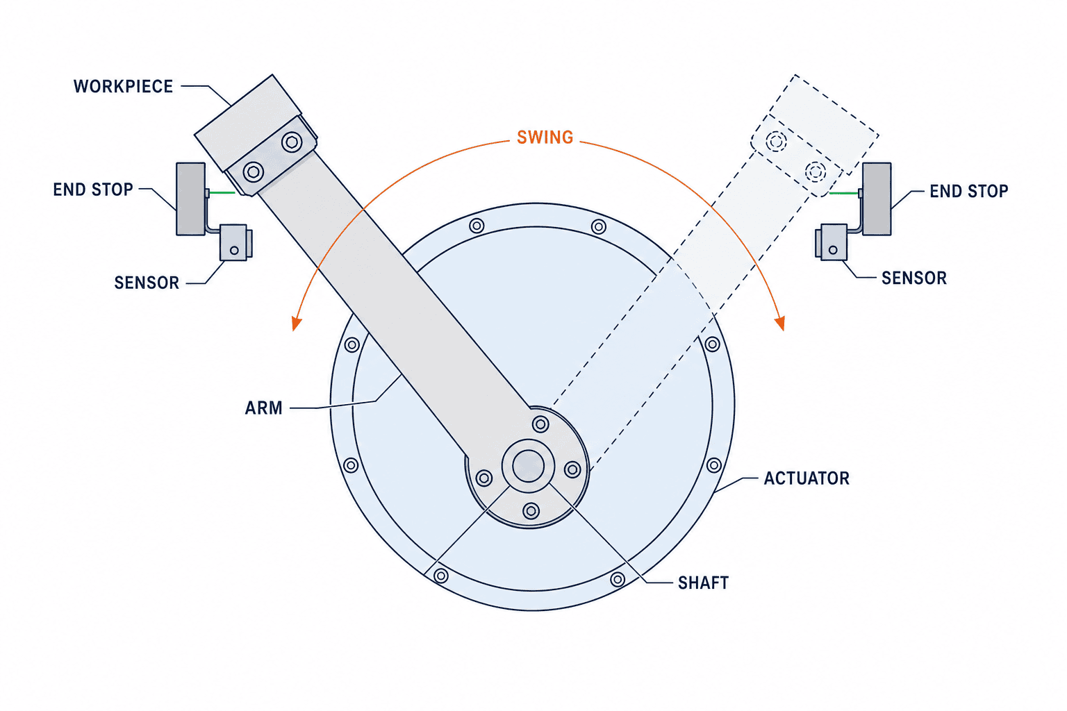
Selecting Oscillation Angles: Looking Beyond the Number 90 Degrees
The labels “90 degrees,” “180 degrees,” etc., for rotary actuators represent only some of the options offered within a series. For example, SMC’s CRB2 vane-type documentation shows that the selectable angles differ between single-vane and double-vane models. For each model, you need to check the angle adjustment range, how to use internal and external stoppers, and available cushion configurations—even within the same series. SMC CRB2 Catalog
When determining the required angle, draw the workpiece’s outline at both the loading and unloading positions, and check for interference and safety distances. If you try to compensate for insufficient angle by forcibly offsetting the jig, inertia and gravitational torque may increase. Conversely, if you select an excessively large angle and stop early with a mechanical stopper, you may not be able to use the internal cushion as intended by the manufacturer’s documentation. Especially when stopping mid-swing with an external stopper, separately confirm the energy absorbed by the stopper and the allowable conditions on the actuator side. SMC’s selection materials distinguish between allowable kinetic energy with and without rubber cushions. SMC Selection Materials
For processes with strict requirements on stop angles, consider combining mechanical stoppers, load-side positioning mechanisms, sensor detection, and product holding force. Rather than expecting precise positioning from pneumatic mechanisms alone, it is better to clarify which component determines the final position—this makes it easier to isolate causes during FAT. State the angle tolerance as a requirement for the entire system, and do not treat it as having the same meaning as the actuator’s catalog value.
Torque Selection: Don’t Confuse Rated Values with Usable Values
Required torque includes load torque from external forces and gravity, friction torque from bearings and jigs, and inertia torque needed for acceleration and deceleration. Parker’s technical documentation explains that required torque should be considered as the sum of these components, with the inertia component described as the product of moment of inertia and angular acceleration. Parker Rotary Actuator Technical Data
To write the basic formula for consideration, the torque required by the load is “torque from external forces and gravity + friction torque + moment of inertia × angular acceleration.” However, the sign and maximum value will change depending on the direction of rotation and orientation. In vertical rotation where the workpiece’s center of gravity is offset from the axis, gravity will assist at some angles and hinder at others, so you cannot determine the maximum load just by looking at the starting point. If you attach a long bracket or heavy chuck horizontally, the mechanical designer should calculate the center of gravity and moment of inertia and provide this load data to the manufacturer.
When reading the torque tables in catalogs, match the indicated pressure conditions with the minimum operating pressure that can actually be secured in your equipment. Use as a reference the pressure at the actuator’s inlet when other pneumatic devices are operating simultaneously, not the compressor’s nominal pressure. If piping is long, there are many fittings, or the valve’s flow capacity is small, the operating pressure may drop below expectations. If you want to check regulator design or settings first, refer to the Pneumatic Regulator Selection Article.
Parker’s PRO/PRN documentation shows a procedure for calculating static torque from required force and arm length, combining resistance and acceleration torque for moving loads, and comparing the actuator’s effective torque at actual operating pressure. Parker PRO/PRN Catalog When including a safety factor in the calculation table, specify what uncertainties it covers. If you lump together unknown friction, future jig changes, and pressure fluctuations into a single ambiguous coefficient, you won’t be able to recalculate properly when specifications change.
Moment of Inertia and Stopping Energy Must Be Evaluated Separately from Torque
Even if the required torque is sufficient, the actuator cannot be adopted if it cannot absorb the kinetic energy of the load at the end of rotation. The SMC CRB2 operation manual provides a method for evaluating kinetic energy based on terminal speed and the load’s moment of inertia, and comparing it to the allowable values for each model and cushion condition. SMC CRB2 Operation Manual The general formula is E = 1/2 × I × ω², where I is the mass moment of inertia about the axis of rotation, and ω is the angular velocity at the end of movement. Since velocity is squared in the equation, if there is a requirement to shorten the cycle time, recalculate the stopping energy.
To simplify calculations, do not simply estimate the workpiece mass and judge it as “light.” Even with the same mass, the moment of inertia increases as components are positioned further from the axis of rotation. For designs where a chuck is mounted at the end of a long arm, calculate the inertia for the arm, chuck, and workpiece separately, sum them, and evaluate them about the common axis of rotation. If you can use the mass properties from CAD, specify the coordinate system and axis of rotation when outputting the data. If the CAD values differ from the actual jig, update them using measured mass and dimensions from a prototype.
Even for the same model, the reference column for allowable kinetic energy may differ depending on whether a rubber cushion is used or an external stopper is employed. The presence of a cushion does not mean it can absorb any load. If the load or speed exceeds the manufacturer’s allowable values, review the mechanical configuration by lowering the speed, reducing inertia, installing appropriate stoppers or shock absorbers, or selecting a more suitable model. Specify in the documentation which components absorb the energy, the adjustment range, and maintenance/replacement procedures.
Confirm Operating Time Together with Valves, Piping, and Speed Controllers
The oscillation time of the actuator alone does not guarantee the actual equipment cycle. This is because the operation is affected by the supply/exhaust valves, flow control, tube diameter and length, fittings, load, and supply pressure. The SMC CRB2 catalog shows the adjustable range of oscillation time by series and size, and also notes that operation should be within the specified range. SMC CRB2 Catalog First, confirm that the required time falls within this range, then measure the forward and return times on the actual machine, including the valves and piping.
Excessively restricting the flow control will hinder short cycle times. On the other hand, if you maximize speed before attempting to suppress stopping shock, the energy at the end position will increase. Speed, shock, and position variation cannot be optimized with a single adjustment knob. Include in your FAT and SAT measurement points the conditions that occur in the equipment, such as periods of low supply pressure, simultaneous operation of multiple units, and cold starts. The article on pneumatic speed controller selection summarizes the key points for checking the flow control side.
When selecting a directional control valve, specify the required port configuration, switching response, piping length, manual operation, and valve position in case of abnormality. Create a circuit diagram showing which coil moves in which direction when energized, how the exhaust side is controlled, and what happens if power is lost while holding the workpiece. The article on pneumatic solenoid valve selection can also be used to organize valve specifications.

Position Detection and Holding Conditions: Do Not Judge Completion Solely by Sensor ON
End sensors indicate that “the actuator has entered the detection range.” However, this alone does not guarantee that the workpiece is in the correct position, the clamp is engaged, or the part can be transferred to the next process. In equipment where the workpiece may shift or the jig has play, consider providing separate position or seating confirmation on the load side. Festo’s product information also shows that position detection can be configured for rotary drives, but always check the sensor types and possible mounting positions for each product. Festo Product Information
For applications requiring holding, consider abnormal situations before relying solely on compressed air to support the load. If there is a risk of the workpiece or jig falling or rotating due to pressure drop, tube rupture, emergency stop, power loss, or valve failure, design for safety by including mechanical locks, stoppers, balancers, load-supporting structures, and exhaust/restart procedures. ISO 4414 defines general rules and safety requirements for pneumatic systems and components used in machinery. Overview of ISO 4414:2010 The specific safety measures required for each machine should be determined separately through risk assessment.
Control specifications should include detection conditions for forward and return ends, timeouts, handling of double ON or both OFF states, restart after stopping, and interlocks during manual operation. When adjusting detection positions, check under low pressure conditions to ensure that the sensor does not turn ON before the stopper is contacted. By visually confirming on the actual machine whether the workpiece is in the correct position when “operation complete” is displayed on the PLC screen, you can clarify the boundary of responsibility between control and mechanical systems.
Practical Procedure for Selecting Pneumatic Rotary Actuators
Selection becomes easier to compare if you proceed in the following order. First, consolidate the shaft orientation, load, required angle, cycle time, stop positions, operating environment, and safety conditions in case of abnormalities into a single specification sheet. Second, determine the minimum pressure conditions for the equipment and calculate the load’s center of gravity and moment of inertia. Third, compare the required torque for both forward and return strokes, at both start and end points. Fourth, check the end-of-stroke energy and cushion/stopper. Fifth, verify shaft load, mounting, sensors, valves, piping, and maintenance parts, and measure the candidates in FAT (Factory Acceptance Test).
In the selection calculation table, record the input values, calculation formulas, data sources, worst-case conditions, adopted model, manufacturer’s verifier, and design change dates. Even after calculations are complete, if there are changes such as piping route modifications, increased jig weight, or shortened sequences, reevaluate the torque and stopping energy. Do not assume that “no change is needed because the model was already selected.” Since pneumatic component product series are updated, always check that the same latest version is referenced at both quotation and ordering stages.
| Confirmation Order | Input/Decision | Common Omissions |
|---|---|---|
| 1 | Application, reciprocating angle, shaft direction, stop positions | Only entering the nominal angle |
| 2 | Mass, center of gravity, and inertia of all movable parts | Calculating only the workpiece |
| 3 | Minimum supply pressure and required torque | Comparing using the compressor’s set pressure |
| 4 | End speed, stopping energy, cushion | Assuming passing torque means passing stop as well |
| 5 | Radial/thrust load, mounting | Applying jig load directly to output shaft |
| 6 | Sensors, valves, piping, safety | Determining workpiece position solely by sensor ON |
| 7 | FAT/SAT measurement and recording | Not reconfirming at on-site pressure |
How to Proceed with Calculation Examples: Define Boundary Conditions Before Entering Numbers
This section explains how to create calculation documents, not to recommend specific manufacturer models. Suppose you have a process where a chuck and workpiece are placed on a rotary table and reciprocated in a horizontal plane. First, divide the rotating parts into table, chuck, workpiece, and mounting hardware, and list the mass, center of gravity, and distance from the rotation axis for each. Next, define the coordinate origin and positive rotation direction on the drawing, and calculate the mass moment of inertia about the same axis. If there are multiple workpiece specifications, check not only the heaviest workpiece but also whether a workpiece with mass concentrated at the periphery results in the maximum inertia. If you select a representative item based solely on weight comparison, you may overlook this condition.
Next, set the target angle and operation time for both forward and return strokes. Distinguish whether the specification value is “from control command to sensor ON” or “from actual movement start to reaching the mechanical stopper.” The overall cycle, which includes valve response and piping fill time, is not the same as the actuator’s swing time. For mechanical calculations, use the speed change of the rotating part; for FAT process capability confirmation, use the time from control command to permission for the next process—separating measurement definitions allows for valid comparisons.
The torque required for rotational acceleration is calculated from the moment of inertia and angular acceleration. However, be sure to record the assumptions made about the time variation of acceleration. A simplified acceleration model can be used for initial candidate comparison, but actual pneumatic drive speed varies with supply pressure, flow rate, friction, and load. Do not determine the end speed solely by the value calculated under the same assumptions—compare with the manufacturer’s selection procedure and actual machine measurements. If there is a large discrepancy, revise the model and do not adopt only the most favorable test results.
Even in horizontal rotation, resistance may be added by jigs or cable routing. For processes rotating in a vertical plane, the gravity torque changes with angle. Therefore, check the increase or decrease in required torque for at least three positions: start, intermediate, and just before the end. If there is a fixed external force, indicate its point of action and direction on the drawing, and consider changes in the moment arm due to rotation. If the point of action is ambiguous and you simply state “required torque is X Nm,” the supplier cannot verify its validity.
If the candidate model table lists torque for each pressure, compare it with the row for the minimum pressure that can be guaranteed on the equipment side. Even if a candidate meets the calculated required torque, it is not adopted if it fails to meet any of the end-of-stroke energy, shaft load, or swing time requirements. By dividing the pneumatic rotary actuator selection table into “torque pass/fail,” “stop pass/fail,” “shaft load pass/fail,” “implementation pass/fail,” and “safety pass/fail,” it becomes easier to reevaluate if conditions change later. If the manufacturer’s response uses different units, indicate both the conversion method and the original units to avoid transcription errors.
Finally, match test conditions one-to-one with calculation conditions. If calculations were done for the maximum workpiece, use the maximum workpiece in FAT as well; if torque was evaluated at minimum pressure, reproduce that pressure. If it is not possible to test under complete abnormal conditions for safety reasons, separately record the range tested and the range substituted by analysis or design verification. In the margin of the calculation sheet, note “what changes would require reselection,” so that maintenance personnel can make judgments when workpieces are changed or cycles are shortened after mass production.
Items to Reconfirm During Design Changes
Even small changes after equipment commissioning can undermine the assumptions of rotary mechanisms. For example, switching the chuck to a different manufacturer’s product, moving the gripping position outward, replacing resin workpiece parts with metal ones, or relocating sensors to more visible positions. Even if the visible extent of the change is minor, increasing the mass farther from the rotation axis affects the moment of inertia. Change requests should include fields for mass and center of gravity, inertia, stop position, and impact on shaft load.
For control changes, pay particular attention to requests to shorten operation time. Proposals to increase speed often involve changing valves or flow control, but the energy that must be absorbed at the end of travel also changes. Under the shortest cycle conditions after the change, confirm the cushion usage conditions and allowable kinetic energy. Simply advancing the sensor ON position to shorten the displayed cycle time can create the risk of starting the next process before the machine has actually stopped, so re-measure the relationship between machine stop and control completion.
Changes to pneumatic sources or piping are also relevant. When adding new equipment to a shared compressor, the pressure drop during peak usage may increase. Conversely, increasing supply pressure can change the direction of faster movement and stop shock. Do not assume that raising the pressure solves everything; reconfirm the allowable conditions for actuators, valves, piping, and cushions. Do not conceal increased stop shock with only on-site adjustments—be sure to document both the change that caused it and the measurement results.
When parts are discontinued or substituted, compatibility cannot be confirmed by mounting dimensions alone. Output shaft shape, seals, sensor mounting, end cushion capacity, bearing allowable load, and operating pressure range may differ. For approval of substitutes, provide the new manufacturer with the same input conditions as the RFP, and determine FAT or on-site re-acceptance items. If purchasing, design, and maintenance use the same selection table, you can avoid the mistaken assumption during emergency replacement that “if it fits, it works.”
To maintain the selection table on-site, also record the reasons for changing model numbers and the reasons for rejecting other candidates. For example: “insufficient torque,” “exceeded shaft load,” “insufficient cushion capacity,” “does not support required angle,” or “sensor cannot be adjusted from maintenance position.” In the future, if delivery times for the same model are extended, knowing the reasons for rejection will help quickly narrow down alternatives. Attach revision numbers to calculation sheets and test records, and link drawing revisions to parts list revisions. If speed adjustments are changed on-site, record the measured values before and after the change and the person who made the change. These are not just to increase paperwork, but to provide information for safely and quickly restoring original conditions in the event of equipment stoppage.
Furthermore, even after passing the acceptance test once, standardize the model numbers and adjustment positions of parts replaced during maintenance. Pneumatic equipment may have different internal specifications even if the appearance is the same. When replacing, check the nameplate against the order model number, and after adjustment, operate both forward and return strokes under actual load, confirming stop position, shock, and signals in order. The scope of changes for which testing can be omitted should be agreed upon and documented in advance by design and maintenance personnel.
Records should be stored in a location accessible on-site.
Items to Include in the Request for Quotation (RFP)
When requesting a quotation, do not simply send “set of pneumatic rotary actuators”; provide comparable conditions. The goal is not just to find the cheapest model, but to ensure that manufacturers and equipment suppliers respond under the same load conditions. Attach drawings, maximum and minimum workpiece mass, moment of inertia around the rotation axis, eccentric distance, direction of gravity, required angle, operation time, allowable stop position deviation, and expected annual/daily cycles. Also specify the actual supply pressure range, air quality, installation environment, and presence of cleaning or dust.
As for the content you want in the response, specify candidate model numbers and current catalogs, effective torque at set pressure, allowable kinetic energy, shaft load, recommended valves and flow control, cushion configuration, position detection method, mounting drawings, replacement parts, and delivery time. Also request alternatives if conditions cannot be met. For example, if a proposal assumes an external stopper, have them specify the stopper’s capacity, mounting position, and maintenance range. If the quotation states “not guaranteed due to load conditions,” inquire which input values are insufficient.
At Thai factories, interpretation of specifications can differ among mechanical, electrical/control, maintenance, and purchasing personnel. Include a responsibility assignment section in the RFP, clearly stating who determines load mass, who designs piping, who judges stop positions, and who evaluates safety risks, to facilitate post-order adjustments. For imported spare parts, also check local procurement feasibility and substitute conditions. Compare not only unit price, but also total cost including ease of replacement to minimize downtime, spare parts inventory, and maintenance training.
What to Check in FAT: Observe Stopping Behavior at the Manufacturing Plant
In FAT, not only check for consistency between drawings and parts lists, but also mount the maximum workpiece and jig as expected, and confirm forward and return operation times, stop shock, end positions, and sensor signals. Pass/fail criteria should be mutually agreed upon in the specification before ordering and not changed to more convenient values during testing. Record multiple cycles and observe variation and abnormal stops. Short no-load runs alone cannot capture shocks or position fluctuations that occur under load.
Measure pressure not only at the equipment inlet but also near the actuator as needed. In addition to normal pressure, reproduce the minimum pressure conditions specified and conditions where multiple axes operate simultaneously. If gravity assists the return stroke, the end speed may be higher than the forward stroke, so record both directions. Also record cushion or external stopper settings, speed controller opening, and sensor mounting positions together with test results. Keep a record of setting changes before and after adjustment so they can be reproduced on-site later.
For abnormal scenarios, actually check emergency stop, pressure drop, power loss, manual operation, and behavior upon power restoration or repressurization. For tests where the workpiece may fall, implement safety measures. The purpose of ISO 4414 is to specify safety requirements for pneumatic systems; it does not mean that it is sufficient for the equipment to simply operate. Overview of ISO 4414:2010 Do not just write “pass” in the test record; also record the conditions, measured values, presence of abnormalities, corrective action owner, and retest results.
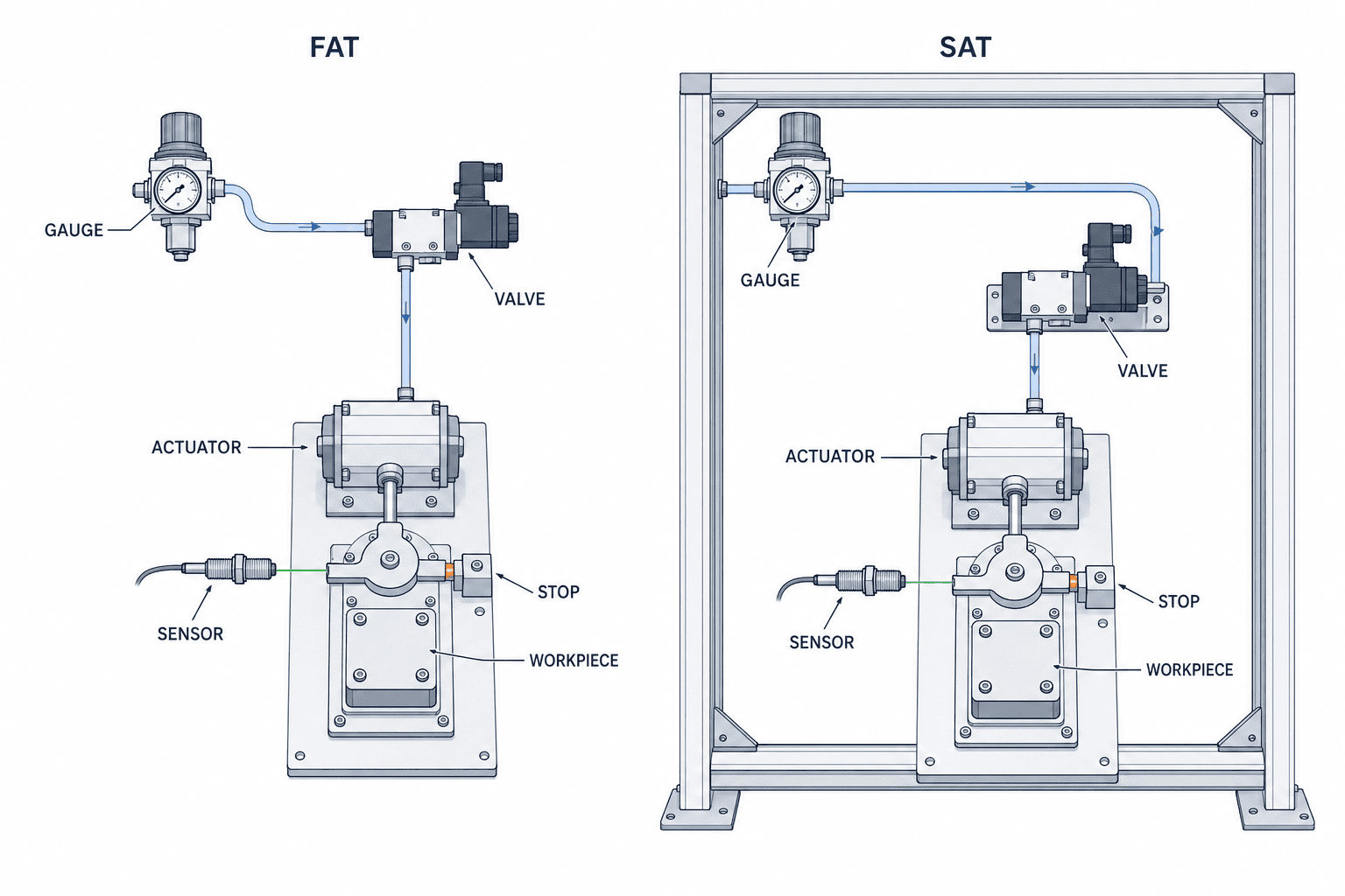
What to Check in SAT: Reproducing Actual Piping and Operating Conditions at the Thai Factory
SAT is the stage where the results from FAT are reconfirmed under the actual conditions at the site. This includes the supply air at the Thai factory, actual piping lengths, simultaneous operation with adjacent equipment, types of workpieces, and operator procedures. Operations that worked at the manufacturing plant using short tubes may not perform identically on site. Check for pressure drops, pipe bends or blockages, valve connection orientation, exhaust restrictions, and sensor wiring. If there are discrepancies with FAT, isolate the cause in the order of mechanical, pneumatic, and control systems.
Pass/fail criteria use the same definitions as FAT for angle, position, reciprocation time, impact at stop, sensor output, and safe operation during abnormalities with the specified workpiece. If differences arise between the machine leveled after installation and its actual operating posture, re-examine the input conditions in the axial and gravity directions. Record the regulator settings used and the allowable downstream pressure range in the operating standards. If the cycle is sped up during post-installation adjustments, recalculate the stopping energy before updating the acceptance values.
At handover, provide a complete set of documents: approved drawings, pneumatic circuit diagrams, selection calculation sheets, FAT/SAT records, maintenance procedures, spare parts, and recovery procedures for abnormalities. If maintenance staff understand “which settings affect stop impact” and “what the sensors are detecting,” unnecessary readjustments after mass production can be reduced. For cases where identical replacement parts are unavailable, define alternative conditions not only by angle but also by torque, shaft load, cushion, mounting dimensions, and electrical signals.
Common Selection Mistakes and How to Correct Them
The judgment “the workpiece mass is small, so a compact unit is fine” overlooks offset distance and moment of inertia. Even if the absolute mass is small, if it is at the end of a long arm, the energy that must be absorbed at stop increases. The corrective action is to determine the mass properties using CAD or actual measurements and check the inertia around the rotation axis. The shorter the required operation time, the higher the priority of this check.
The assumption “there’s enough margin in the catalog torque, so stopping is also fine” is also incorrect. The torque required to move and the energy absorbed at the end position are separate constraints. The corrective action is to check the allowable kinetic energy for the relevant model and cushion configuration in the manufacturer’s documentation, and measure the actual end speed during FAT. If using an external stopper, design verification must include the stopper’s capacity.
The judgment “the end sensor is ON, so positioning is complete” overlooks jig play and workpiece seating. The corrective action is to specify in the control specification what the sensor detects, and define workpiece posture and clamp state, which determine quality, as separate conditions. The quick fix “just replace the valve on site to speed things up” is also risky. Increasing speed changes the stop conditions, so after changing the valve and piping, re-evaluate operation time, impact, and energy.
Summary: Create a Selection Table and Verify with Actual Load
Selection of pneumatic rotary actuators becomes easier if you treat required angle, rotation axis and load, effective torque under worst-case conditions, moment of inertia, end energy, shaft load, stop position, and safe operation as a unified set of conditions. In procurement, compare candidates using the same input conditions, and in FAT and SAT, use the same pass/fail definitions to verify under actual load. Final model and settings should be determined based on the manufacturer’s current documentation, equipment risk assessment, and actual measurements.
Consult TOMAS TECH: If you need support for tasks such as organizing load data, selecting mechanisms and pneumatic circuits, or creating FAT/SAT items for workpiece flipping, gate switching, or jig rotation at your Thai factory, please let us know your application, workpiece drawings, and desired cycle via our contact page. We also accept consultations on causes of stop impact or position variation in existing machines.
Reference Information
- SMC CRB2 Vane Type Rotary Actuator Catalog: Swing angle, pressure, time adjustment, allowable kinetic energy, shaft load.
- SMC CRB2 Operation Manual: Checking kinetic energy based on moment of inertia and end speed.
- SMC Rotary Actuator Selection Guide: Cushion usage conditions and allowable kinetic energy.
- Parker Pneumatic Actuator Engineering Data: Concepts of torque including load, friction, inertia, and cushion.
- Parker PRO/PRN Rotary Actuator Catalog: Selection procedures and effective torque verification at operating pressure.
- Festo Rotary Actuator Product Information: Explanation of product range regarding type, position detection, and end conditions.
- ISO 4414:2010: Overview of general rules and safety requirements for pneumatic systems and components.


