


Mechanical limit switch selection begins with the motion, not the part number. What touches the switch, from which direction, at what speed, and where must the signal change? A roller-lever switch may work reliably on one machine and fail early on another if the cam enters from the wrong side or pushes past the permissible travel. This guide follows a practical sequence for Thai factories: separate the detection function, draw the cam and actuator together, check travel and electrical ratings, specify the installation, then measure acceptance criteria in FAT and SAT. Its examples concern ordinary machine position and travel detection. A personnel safety function requires its own risk assessment, suitable safety components and validated safety circuit.
Distinguish position confirmation from a safety function
A limit switch physically senses a moving component. Common applications include a fixture seated in place, a conveyor stopper at its end position, a cylinder extended, a lift at its upper travel limit, or a cart approaching a transfer point. These are different functions. A production sequence may only need confirmation before the next step. A final machine limit may need to stop motion under a control fault. A guard interlock protects people and needs a separate safety design.
Before requesting quotations, record one line per detection point: machine and point ID, moving part, approach direction, minimum and maximum speed, desired ON and OFF states, action on an unexpected state, and maintenance access. A bill of materials stating “four limit switches” leaves too much to interpretation. General-purpose switches must not be treated as a substitute for a validated guard interlock. Our safety door switch guide addresses guard locking, safety wiring and verification separately.
Choose the actuator together with its cam
The actuator head and the cam or dog that drives it form one mechanical system. OMRON’s selection guide compares roller levers, adjustable roller levers, plungers, roller plungers and other heads by pretravel (PT), overtravel (OT), operating force and repeatability. A roller lever can accommodate a lateral moving cam and a comparatively generous motion range. A plunger can suit a short, nearly axial push, provided side loads are controlled. An adjustable head is useful only when its setting is fixed and verified after adjustment.
| Motion at the detection point | Candidate to evaluate | Critical check |
|---|---|---|
| Cart or slide passes from the side | Roller lever | Approach angle, speed, permitted direction and return path |
| Rigid fixture pushes axially | Plunger or roller plunger | Side load, contact face and full stroke |
| Variable mechanical end position | Lever with suitable travel | Worst-case tolerance at both ends of the range |
| Approach from two directions | Head rated for the intended directions | Do not assume a one-way head works both ways |
A sharp cam edge should not hammer the roller. Smooth the contact face and ensure the return edge does not flick the lever. OMRON publishes specific relationships between cam angle, speed and travel for its products. Such figures are model-specific examples, not universal speed limits. Confirm the selected model’s documentation against the actual motion path. At high speed, measure stopping distance and impact before finalising the mounting position.
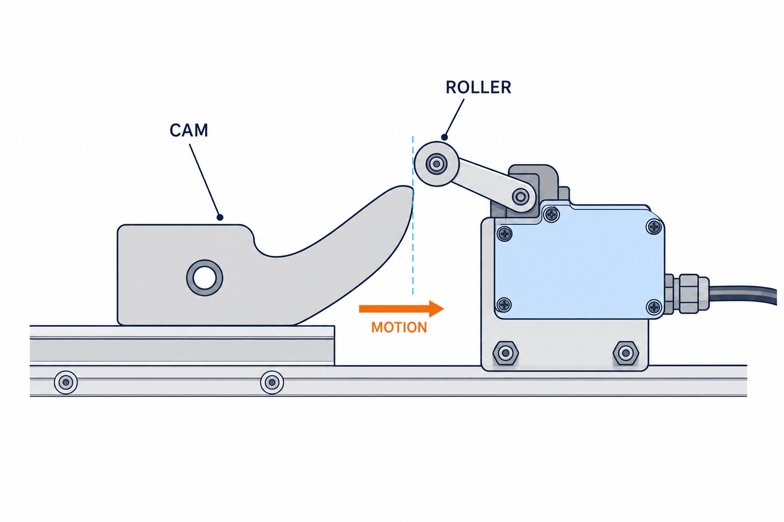
Translate PT, OT, TT and OP into machine coordinates
PT is movement from the free position to switching; OP is the position at which the contact operates; product OT is the travel from OP to the total-travel position (TTP); and TT is travel from the free position to TTP. Product OT is not the amount by which the real machine must push the actuator. Measure actual post-operation push-in separately from OP to the cam’s final position; it must be sufficient for stable operation and must not pass TTP. The manufacturer’s definitions and measuring conditions govern a particular model. Do not design the machine to stop exactly when the contact first changes. Tolerance, heat, vibration and control delay all shift the actual stopping position, while contacts near the operating point can become unstable.
Plot three points on one machine-coordinate drawing: first actuator contact, electrical switching and the worst-case final machine position. Then check both tolerance extremes. If the cam contacts the switch early, can it crush the head? If it contacts late, is there enough movement for the PLC to see the input and stop? Consider a powered-up machine with the cam already on the head, reverse motion, warm operation and maximum load. An independent mechanical stop may be needed; the switch body should not absorb the moving assembly’s kinetic energy.
| Data | Engineering question | FAT/SAT evidence |
|---|---|---|
| PT and OP | Where does the input change? | Record machine coordinate and PLC state on repeated slow approaches |
| Product OT vs actual post-operation push-in | Is measured push-in sufficient for stable operation and within TTP? | Measure OP and final position at maximum relevant speed and load; compare with the product data |
| TT | Could the head bottom out? | Check both cam and mounting tolerances |
| Reset position | When does the input return? | Log reverse cycles and compare switching points |
Match the contacts to the PLC input and load
Mechanical switches may offer NO, NC, 1NO+1NC or multiple contacts, with snap or slow action. Rockwell Automation’s sensor reference explains that snap action changes contact state comparatively independently of actuator speed, while slow action follows the actuator’s speed and travel. Select the contact arrangement together with the controller’s normal-state logic, fault alarm and restart sequence.
Even for a non-safety PLC input, cable break behaviour matters. NC wiring can make some broken-wire conditions easier to notice, but it does not create a safety function. Contact welding, mechanical sticking, shared wiring and input-card failure remain possible. State the input voltage and current, minimum applicable switching load, cable length, noise environment, contact material and terminal arrangement. If a contact drives an inductive load directly, check the relevant utilization rating and suppression circuit. A headline thermal current value alone does not prove suitability for that load.
IEC 60947-5-1:2024 covers electromechanical control circuit devices used for control, signalling and interlocking. Compliance with the standard does not, by itself, establish a machine’s required mechanical life, contact circuit suitability or personnel safety performance. Record those requirements explicitly on the electrical and mechanical drawings.
Check the completed installation, not only the enclosure IP rating
Water, coolant, oil mist, dust and cleaning chemicals reach switches differently. Check body material, seal and temperature rating, but also the cable gland, connector, cable diameter, unused openings, mounting orientation and drainage path. Schneider Electric’s XC catalogue illustrates how head, housing, cable entry, protection and operating limits differ by configuration. An IP rating on a component sheet does not prove chemical resistance or the protection of a poorly fitted cable gland.
Survey the real point of installation. Is the switch in a direct washdown stream? Does a cable form a water trap above the gland? Does vibration loosen a bracket? Are cleaning chemicals compatible with the seal and cable jacket? Ask the manufacturer about chemical compatibility rather than infer it from an IP number. OMRON’s troubleshooting guide lists cam geometry, wrong operation direction, excessive speed or stroke, and actuator wear among common mechanical failure causes. Increasing the enclosure rating alone will not correct those faults.

Compare mechanical and non-contact sensing by failure mode
A non-contact sensor may reduce wear, but it introduces different design conditions. An inductive proximity sensor depends on metal target, actual sensing distance, mounting and wiring. A photoelectric sensor depends on its optical path, background, contamination and lighting. A mechanical limit switch can detect a deliberately designed physical cam independent of target material, but its actuator and cam require inspection.
| Criterion | Mechanical limit switch | Inductive proximity sensor | Photoelectric sensor |
|---|---|---|---|
| Target | Part or cam that can actuate the head | Usually metal | Target meeting optical conditions |
| Wear | Contact wear and mechanical adjustment | No target contact | No target contact |
| Position basis | Cam geometry plus switch travel | Target material and sensing margin | Beam alignment and light margin |
| Main risks | Impact, excessive stroke, damaged lever | Insufficient sensing margin, wiring | Dirt, reflections, changing background |
Compare the detection failure, replacement time, installation constraints and behaviour during power loss in one table. Neither “non-contact is always better” nor “mechanical means guaranteed” is a sound design rule.
Write one comparable RFP for switch and cam
The request for proposal should contain five linked sets of information:
- Mechanics: drawings and mounting holes, cam geometry, approach direction, maximum and minimum speeds, stopping delay, dimensional tolerance and cycle rate.
- Detection: coordinate at which the state must change, expected ON/OFF logic, repeatability, return motion and power-up position.
- Electrical: PLC input, contact arrangement, load category, cable or connector, grounding and noise conditions.
- Environment: temperature, dust, washdown, oil and chemicals, vibration, impact and maintenance access.
- Acceptance: FAT/SAT test modes, measurement method, pass criteria, fault simulation, records and spare parts.
“Model A or equivalent” should be judged on more than bolt pattern. Compare PT, OT, TT, permitted actuation direction and speed, contact rating, minimum switching load, protection, temperature, cable entry and life data. Also price the bracket, cam, guard, gland, cabling, PLC modification, drawings, commissioning, spares and training separately. Product price and availability vary with model, supplier, currency and stock; a common, measurable specification is a better basis for quotations than an old internet price.
FAT: measure switching and travel margin
At factory acceptance, test the input and the mechanics. Approach slowly several times to record OP and reset position. Run at operating speed to measure maximum compression and any vibration or double pulse. If the cam passes through, check whether its trailing edge strikes or lifts the lever. Do not hide chatter by increasing the PLC input filter until the cam, bracket and wiring have been inspected; a longer filter also delays detection.
A useful test matrix covers slow and rated speed, empty and maximum load, forward and reverse, cam engaged or disengaged at power-up, and a post-adjustment check. Prioritise combinations by the consequence of a missed signal. Simulate a disconnected cable, misplaced cam or stuck head where this can be done without damaging the equipment. Record model and lot, installation photos, conditions, measured positions, pass/fail, corrections and signatures. Do not deliberately crush the switch as a test; verify worst-case geometry by measurement or fixture.
SAT: verify the real factory conditions
At site acceptance, repeat the critical measurements with actual workpieces and operating speed. Installation level, vibration, heat sources, coolant spray, cable routing and bracket alignment may differ from the builder’s factory. Check that the PLC input, alarm name and maintenance manual use the same point identifier. Include at least the languages actually used by the maintenance team. A switch that is hard to reach, unlabeled, or impossible to replace at its original position will increase downtime.
Include a replacement method in the handover pack. After a swap, technicians should compare the new switching point, maximum travel and return position with the SAT baseline. If a local substitute may be purchased later, keep an equivalence sheet for actuator head, contacts, environmental rating and cable entry, rather than merely listing another part number.

Maintain both the actuator and its cam
Inspection should include roller wear, shaft play, bent levers, cam burrs and looseness, bracket cracks, cable jacket damage, gland tightness, and signs of water or oil ingress. Recurrent failure after replacing the switch points to the cam, speed, direction, excess stroke or mounting rather than simply a poor component. OMRON’s fault guide supports this diagnosis.
Do not set a maintenance interval by dividing catalogue mechanical-life cycles by daily cycles alone. Impact and environmental conditions alter real life. Use site failure history and trends in switching or reset position. Preserve model, head, contact-block and cable versions in spare-part records. Following every mechanical adjustment or replacement, repeat the measured acceptance points rather than stopping at a PLC “ON” indication.
Three procurement mistakes to avoid
First, buying a visually similar replacement without checking travel, contact arrangement and cable entry can create a new failure. Read the full existing model, measure the cam and document the original switch point. Second, using the switch as the machine’s physical stop risks immediate damage; deceleration and a separate mechanical stop belong in the mechanism. Third, assuming an NC contact alone provides personnel safety ignores actuator failure, welded contacts, circuit faults and validation. A safety application needs its own design and verification, including the required stopping behaviour.
FAQ: mechanical limit switch selection
Roller lever or plunger: which should I specify?
A roller lever suits many lateral cam movements and can provide more travel margin. A plunger suits a short, nearly axial push if side force is controlled. Draw the real motion and compare the selected model’s travel, force, speed and allowed direction before deciding.
Does IP67 make the switch suitable for coolant or washdown?
Not automatically. Verify the assembled connector or gland, cable jacket, cleaning chemicals, temperature and water direction. Ask the manufacturer about oil and chemical compatibility.
Is NO or NC better for a PLC input?
Choose from the required normal state, fault behaviour and restart logic. NC may aid certain broken-wire diagnostics, but does not make the circuit safety-rated. Verify faults during FAT.
Should we replace it with a proximity sensor?
Consider non-contact detection if actuator wear or frequent mechanical adjustment is costly. Then recheck metal material, sensing margin, mounting, power supply and PLC interface. Compare failure modes and replacement effort, not just the unit prices.
What belongs in the quote and FAT/SAT criteria?
Provide cam drawing, speed and tolerance envelope, switching point, PT/OT/TT, contact load, environment and cable scheme. Measure switching, maximum travel and reset in FAT; repeat critical measurements with actual workpieces at SAT.
Conclusion
A mechanical limit switch is a small part at the intersection of motion, controls and maintenance. Select it in five steps: define the detection function, draw the cam path, compare operating and final positions with travel limits, specify contacts and environment, then measure the margin in FAT and SAT. Keep ordinary position detection separate from personnel safety functions.
If a Thai plant is replacing repeatedly failing switches, qualifying an equivalent part, or preparing a machine RFP, contact TOMAS TECH. An initial discussion can start with the detection points and motion even before the final equipment specification is fixed.


